Safety precautions in ship include regular safety drills for crew members, ensuring all safety equipment is in proper working condition, and adhering strictly to international maritime regulations and guidelines to prevent accidents and ensure the safety of passengers and crew at all times.
- Fire safety and fire fighting operations
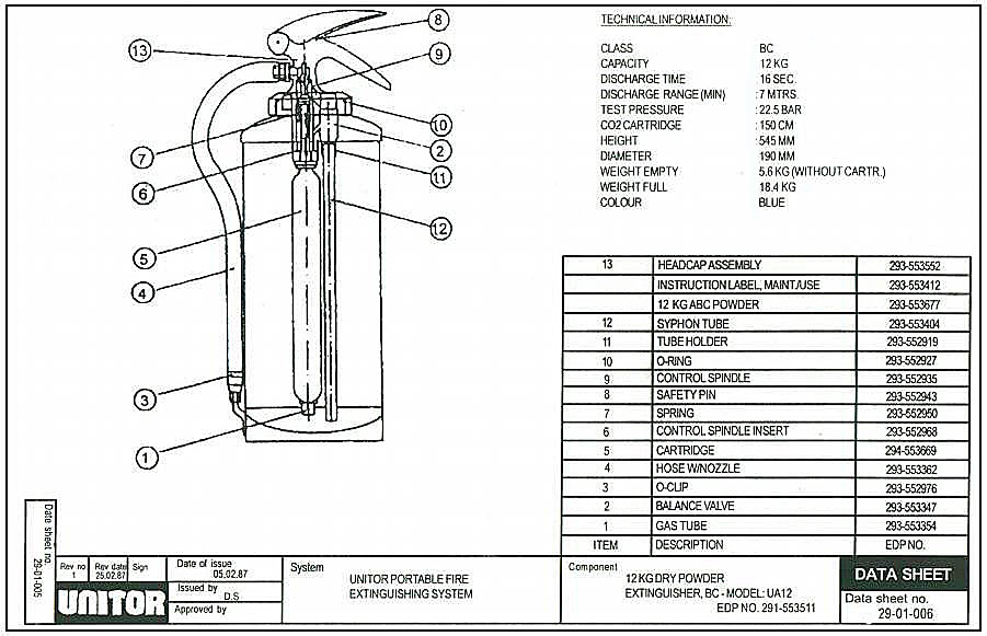
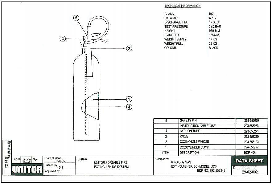
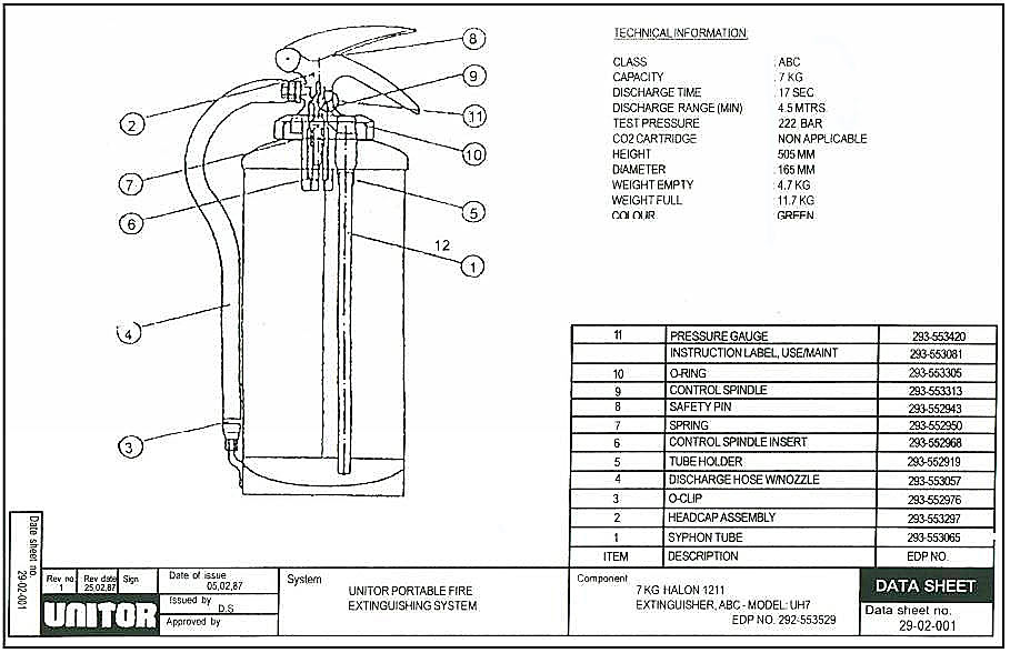
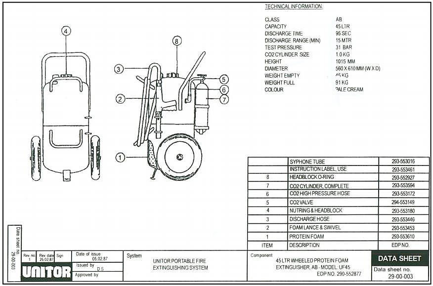
- Portable fire fighting equipment
- Ship fixed fire fighting equipment water spray systems
- Accommodation and service spaces
- Machinery spaces
- High-pressure water spray installation
- Green fire-fighting
- Carbon dioxide flooding system
- Pressure vessels
- Halon system – BTM/BCF
- Inert gas system
- Low expansion foam system
- Medium expansion foam system
- High expansion foam system
Some key safety measures include regular safety drills, wearing appropriate safety gear, following safety procedures, maintaining equipment, keeping work areas clear, knowing emergency procedures, monitoring weather conditions, adhering to regulations, and promoting a safety culture onboard. These precautions help mitigate risks and enhance safety on ships.
Precautions to be taken when entering enclosed spaces
A dangerous space is defined in the regulations as any enclosed or confined space in which it is foreseeable that the atmosphere may at some stage contain toxic or flammable gases or vapours, or be deficient in oxygen, to the extent that it may endanger the life or health of any person entering that space.
The master is required to ensure that all unattended dangerous spaces are secured against entry, except when it is necessary to enter.
Employers must have procedures in place for entering and working in confined spaces, and it is the master’s responsibility to ensure these are followed. No person should enter or remain in a dangerous space except in accordance with the set procedures.
The following precautions should be taken as appropriate before a potentially dangerous space is entered so as to make the space safe for entry without breathing apparatus and to ensure it remains safe whilst persons are within the space.
- A competent person should make an assessment of the space and a responsible officer to take charge of the operation should be appointed.
- The potential hazards should be identified.
- The space should be prepared and secured for entry.
- The atmosphere of the space should be tested.
- A «permit-to-work» system should be used.
- Procedures before and during the entry should be.
Where the procedures listed at 1 to 4 in the previous paragraph have been followed and it has been established that the atmosphere in the space is or could be unsafe then the additional requirements including the use of breathing apparatus should also be followed.
No one should enter any dangerous space to attempt a rescue without taking suitable precautions for his own safety since not doing so would put his own life at risk and almost certainly prevent the person he intended to rescue being brought out alive.
An Emergency Escape Breathing Device (EEBD) is a supplied air or oxygen device, only to be used for escape from a compartment that has a hazardous atmosphere, they should not be worn by a rescuer to attempt a rescue of persons in any circumstances.
EEBDs shall not be used to fight fires, entering oxygen deficient voids or tanks, or worn by fire fighters. In these events, a self-contained breathing apparatus, which is specifically suited for such applications, should be used. If it is found that it is not possible to enter a tank wearing a self-contained breathing apparatus the bottle harness can be removed and passed through the access but the face mask must always be worn.
It is recommended that any person entering a potentially dangerous space should wear a personal gas detection meter capable of detecting oxygen deficiency, Flammability, Explosion and other Hazards of Liquefied Gastoxic gases and explosive atmospheres.
Safety measures for hot and cold work
Based on the findings of the risk assessment, appropriate control measures should be put into place to protect those who may be affected. This chapter highlights some areas which may require attention in respect of hot work.
Operators should be competent in the process, familiar with the equipment to be used and instructed where special precautions need to be taken.
Where portable lights are needed to provide adequate illumination, they should be clamped or otherwise secured in position, not hand-held, with leads kept clear of the working area.
Harmful fumes can be produced during these operations from galvanizing paint and other protective materials. Oxygen in the atmosphere can be depleted when using gas cutting equipment and noxious gases may be produced when welding or cutting. Special care should therefore be taken when welding and flame-cutting in enclosed spaces to provide adequate ventilation. The effectiveness of the ventilation should be checked at intervals while the work is in progress, and if appropriate local exhaust ventilation should be considered. In confined spaces, breathing apparatus may be required.
Before welding, flame-cutting or other hot work is begun, a check should be made that there are no combustible solids, liquids or gases, at, below or adjacent to the area of work, which might be ignited by heat or sparks from the work. Such work should never be under taken on surfaces covered with grease, oil or other flammable or combustible materials. Where necessary, combustible materials and dunnage should be moved to a safe distance before commencing operations. Such places should also be free of materials which could release flammable substance for example if disturbed.
When welding is to be done in the vicinity of open hatches, suitable screens should be erected to prevent sparks dropping down hatchways or hold ventilators.
Port holes and other openings through which sparks may fall should be closed where practicable.
Where work is being done close to or at bulkheads, decks or deck heads, the far side of the divisions should be checked for materials and substances which may ignite, and for cables, pipelines or other services which may be affected by the heat.
Preparation and Execution Cargo Operations LNG and LPGCargo tanks, fuel tanks, cargo holds, pipelines, pumps and other spaces that have contained flammable substances should be certified as being free of flammable gases before any repair work is commenced. The testing should include, as appropriate, the testing of adjacent spaces, double bottoms, cofferdams etc. Further tests should be carried out at regular intervals and before hot work is recommenced following any suspension of the work. When preparing tankers and similar ships all tanks, cargo pumps and pipelines should be thoroughly cleaned and particular care taken with the draining and cleaning of pipelines that cannot be directly flushed using the ship pumps.
Welding and flame-cutting operations should be properly supervised and kept under regular observation. Suitable fire extinguishers should be kept at hand ready for use during the operation.
A person with a suitable extinguisher should also be stationed to keep watch on areas not visible to the welder which may be affected.
In view of the risk of delayed fires resulting from the use of burning or welding apparatus, frequent checks should be made for at least two hours after the work has stopped.
Ship/Shore Safety Checklist
The Meeting
Content of the meeting maybe within the scope of the following broad outline:
- Names and roles of terminal and ship personnel responsible for the cargo transfer operation.
- Terminal representative, check that the pre-arrival instruction to the ship on cargo, cargo disposition and cargo conditioning have been carried out. Also check all necessary ship equipment inspections and tests have been performed.
- Similarly, the ship officers should where possible, satisfy themselves that the relevant terminal equipment and inspections test have been performed.
- When necessary, customs and surveyors will be informed of the cargo tank data. (temperature, pressure, etc.).
- Agree the quantity and types of cargo to be loaded or discharged, in what order, transfer rate and receiving tank allocations.
- Cargo transfer operation should be planned thoroughly and discussed in order to assure full mutual understanding.
- Previous three cargoes last carried by the ship and the relevant dates should be noted in order to identify and assess possible cargo contamination.
- Appropriate cargo data sheet provided and posted.
Safety requirements
Responsibility for the safe conduct of operations on board your ship while at our rests with you as master. Nevertheless, since our personnel, property and other shipping may also suffer serious damage in the event of accident aboard your ship, we wish, before operations start, to seek your full co-operation and understanding on the safety requirements set out in the Ship/Shore Safety Check List.
These safety requirements are based on safe practices widely accepted by oil and terminal industries. We therefore expect you and all under your command to adhere strictly to them throughout your stay alongside this terminal. We, for our part, will ensure that our personnel do likewise and cooperate fully with you in the mutual interest of safe and efficient operation.
In order to assure ourselves of your compliance with these safety requirements, we shall, before the start of the operations and thereafter from time to time, instruct a member of our staff to visit your ship. After reporting to you or our deputy he will join one of your officers in a routine inspection of cargo decks and accommodations spaces.
If we observe any infringement on board your ship of any of these safety requirements, we shall bring this immediately to the attention of yourself or deputy for corrective action. If such action is not taken in a reasonable time we shall adopt measure which we consider to be the most appropriate to deal with situation and we shall notify you accordingly.
If you observe any infringement of these requirements by terminal staff, whether on the jetty on-board your ship, please bring this to the notice of our representative who is nominated as your contact during your stay in port. Should you feel that any immediate threat to the safety of your ship arise from any action on our part, or from equipment under our control, you are fully entitled to demand an immediate cessation of operations.
Fire safety and fire fighting operations
Types of fire
Class A
- Combustible materials fires.
Class B
- Flammable Combustible Liquids.
- Liquid Petroleum Gas Fires.
Class C
- Electrical Equipment Fires.
Class D
Metal Fires:
- Combustible Materials Fires. Example of such fires are bedding, clothing, cleaning rags, woods canvas, ropes and paper fires.
- Liquid Petroleum Gas Fires. As fire involving escaping liquefied petroleum gas from leaking pipes, valves or containers.
- Electrical Equipment Fires. As fire caused by short circuit, over heating or spreading of a fire from elsewhere.
| Methods of controlling fire | ||
|---|---|---|
| Category | Materials | Extinguishing method |
| A | Fibrous (wood, cloth, paper) | Cool below flashpoint |
| B | Flammable Liquids and Gas | Cut-off oxygen supply |
| C | Electrical | Chemical |
| D | Metal | Cut-off oxygen supply, cool below flashpoint |
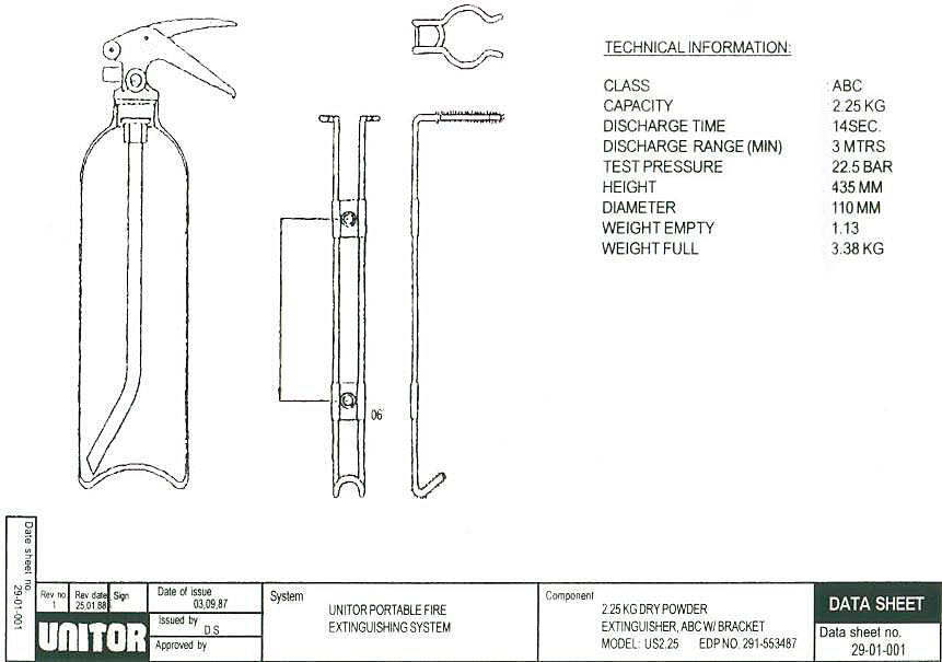
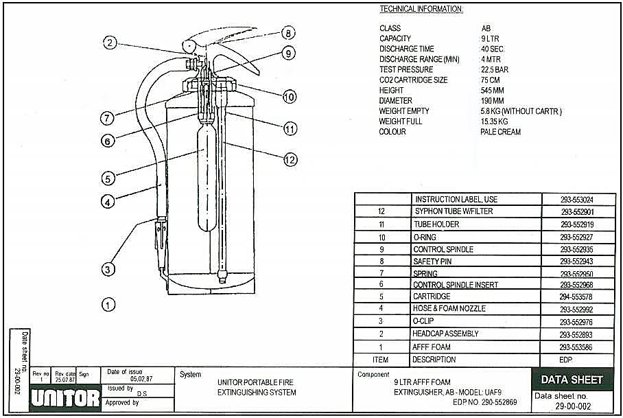
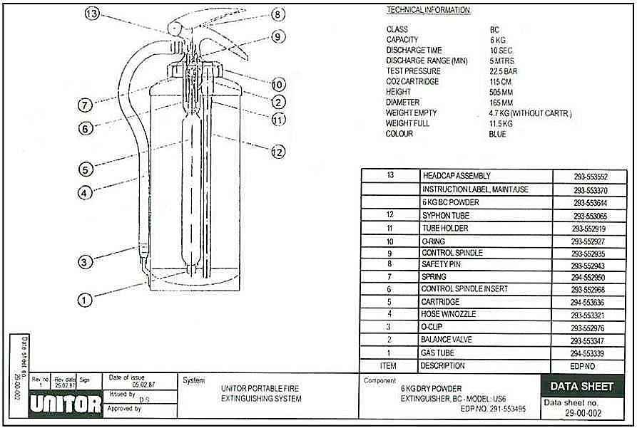
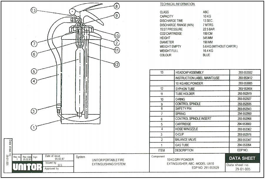
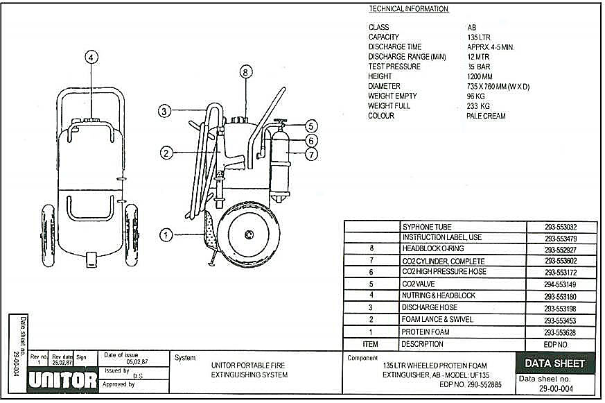
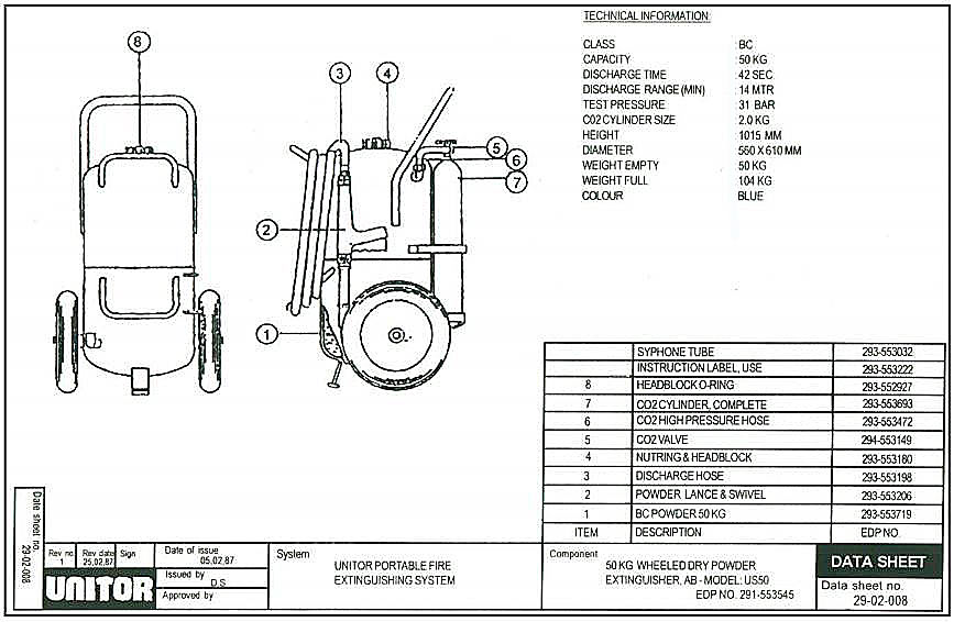
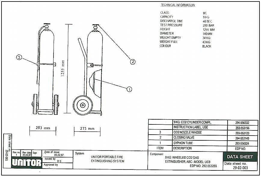
Portable fire fighting equipment
General
Portable fire extinguishers should be made available at each berth to allow terminal personnel to attack an outbreak of fire immediately in order to limit the area of fire, to extinguish the fire and thereafter to prevent reignition.
Foam extinguishers
Small foam extinguishers with capacities of about 10 liters are too limited to be effective in most cases in the event of a fire at a terminal.
Pre-mixed foam appliances in the order if 100 liters capacity are most effective for use at berths. These produce 1 000 liters of foam and it is desirable to have a jet length of about 12 meters.
High expansion foam, adequately applied to the surface of a burning liquid pool, suppresses flame into the liquid beneath it and reduces the vaporization rate. Consequently, the intensity of the pool fire is reduced. Continuous application is required in order to maintain a foam depth desirable to achieve such action.
Dry chemical powder extinguishers
Dry chemical powders such as sodium bicarbonate and potassium bicarbonate can be very effective in extinguishing small LNG or LPG fires. Gas Carriers are required by the Gas Code to be fitted with fixed dry powder system capable of delivering powder to any part of the cargo area by means of fixed monitors and hand held hoses.
It is also common for jetty manifold areas to be protected by substantial portable or fixed dry powder systems. Dry chemical powders are effective in dealing with gas fires on deck or pressure fires from pipelines, and sometimes mast risers.
Dry chemicals attack the flame by absorbing free radicals in the combustion process but have negligible cooling effect. With this, there is no guarantee that reignition with occur since there is still the presence of heat and flammable mixture.
Carbon dioxide extinguishers
Carbon dioxide extinguishers have little value at berths or on jetties except at points where minor electrical fires could occur. This is so because on the jetty side the continuous presence of wind will tend to blow the gas away from the burning area.
Electrical sub-stations located on jetties should be provided with an adequate number of carbon dioxide extinguishers or may have a fixed carbon dioxide system installed.
Water
Water should never be applied to a burning liquefied gas pool as this would provide a heat source for more rapid vaporization of the liquid, thereby increasing the rate of burning. Nevertheless, water remains an important fire extinguishing medium for both solid and liquid fires.
Being abundantly available, water is an excellent cooling agent for surfaces expose to radiation or direct fire impingement. In some circumstances water can be used to extinguish a jet of burning gas, but this method is not always desirable.
Fixed water systems (water wall and water curtain) are customary in the performance of boundary cooling of ship’s structures such as the accommodation; decks tanks and piping, shore storage tanks and the ship’s structure (in the case of LNG carriers).
Ship fixed fire fighting equipment water spray systems
Any member of the crew may find a fire in its early stage, before the automatic fire alarm system has been operated. By prompt and intelligent action, using the portable or non-portable extinguishers at hand, he can avert a major conflagration.
If the fire is large, it is necessary to resort to the use of fixed installations. It is of the utmost importance that each crew member should familiarize himself/herself with all such installations.
Accommodation and service spaces
The accommodation and service spaces are not required to be fitted with any form of fixed installations, although a certain amount of structural fire protection is required under the Merchant Shipping (Cargo Ship Construction) Rules.
Passenger ships, when built to certain methods, as laid down by IMO (International Maritime Organization), have to have an automatic sprinkler and fire alarm system fitted for the detection and extinguishments of fire in all spaces in which a fire may be expected to originate. Some tankers have fixed sprinkler systems in the cargo pump rooms.
A schematic diagram of a typical sprinkler system is given. The system incorporates a number of «sprinkler heads» which are supplied with water under constant pressure. Sprinkler Heads, are arranged so that every part of each space requiring protection is adequately covered. Each head has a glass of quartzoid bulb fitted partially with a special liquid. As the liquid expands, due to heat, it fills the bulb entirely, and being unable to with stands any further pressure, the glass will shatter, thus activating the system. The water pushes the diaphragm out and then flows from the sprinkler head.
The sprinkler head bulbs are designed to rupture at certain temperatures, which are 68 deg. C (155 deg F), 79 deg. C (175 deg. F) and 93 deg. C (200 deg. F). The higher temperature would be used in the hotter parts of the ship.
Under the pressure of 5,5 bars (80 p. s. i.) to 8,3 bars (120 p. s. i.) maintained in the reserve tank by a compressed air supply, the water is deflected upwards and outwards and broken onto a find spray by the serrated edge of the sprinkler base. Area of coverage by one sprinkler is approximately 12 square meters (169 square feet). When the pressure falls to a lower limit, the water pump starts up automatically. There are generally not more than 200 hundred heads per section.
A small valve is incorporated for testing purposes. When this is opened, it allows the same flow through the valve as a sprinkler heads and confirms that the alarm system is in order. This method can also be used to give the alarm if a small fire is discovered before a sprinkler glass bulb has had time to shatter. The control valve must be open at all times except when sprinkler heads are being replaced so it is either locked open or has an electric alarm to show if it has been accidentally shut.
The whole system use initially charged with fresh water to prevent corrosion but the pump supplies sea water. When the system has been operated, the system must be drained, flushed through and refilled with fresh water. The system must be tested once a week, and charged with sea water each time. A drained valve is fitted in the pumped discharged line. By opening this valve and closing the cock at the pressure-operated switch and the pump-discharge valve, the pump can be allowed to cut in automatically as required and discharged to the bilges. Some systems are left dry when not in use.
Machinery spaces
The machinery spaces of certain cargo and passenger ships, depending on the type and horsepower of the machinery and vessel’s size and class, are required by law to be fitted with a fixed Fire protection and Fire extinction on Liquefied Gas Carriersfire-extinguishing system. The water spray system is recognized type. The center shows such as system for passenger ship, cross-connected to the sprinkler system provided for the protection of the accommodation and service spaces and the drencher system referred to later.
The main difference between the machinery space water system and the sprinkler system is that the former is manually operated whereas the sprinkler is automatic. The sprayer head is similar to the sprinkler head but has no glass or quartzoid bulb and has different types of deflector based being used to vary the spray pattern required.
The system is pressurized by fresh water, pressure being maintain to the section control valves at all times. An air vessel is incorporated in the system to prevent the pump (controlled by pressure switch) from cutting-in due to sight water leaks.
When the section control valve is opened, water under pressure is supplied to the various sprayer heads that are fitted in the bilges, over tank tops or on the other areas where oil may accumulate.
The system may also be divided into zones so that water may be directed only to those areas involved in a fire.
Pumps and controls are fitted outside the space to be protected so that a fire in the protected area cannot put the system out of action.
The system should be tested regularly by operating the various section control valves, but great care must be taken to ensure water is not sprayed over electrical equipment, etc., as serious damage could occur. Every effort should be made to vary sections tested. If an airline connection is provided, then as many section as possible should be proved clear, remembering that the automatic operation of the pump can be proven only by actual test. The external power to the unit and the mobile hand sprayer must all be tested regularly.
In vogue now is the flood system, a diagram of which is shown on the right side. The system consists of a distribution network of pipes supplied with water from a drencher pump to which are connected open drencher heads. The system covers the entire vehicle deck and is divided into zones. Each zones has its own control valve and the pump capacity is such that at least the two longest adjacent zones can be supplied simultaneously at their rated capacity. Thus, irrespective of where a long vehicle is parked, all parts of it are within the range of the spray heads. These heads are similar to the machinery space heads (i. e. no glass bulbs fitted), their spacing and application rate being governed by the deck head height. Thus when the deck height is 2,5 meters (8 feet) or more, the spacing of the head requires to such that a water application rate onto the deck of 5,0 liters/square meter/min is possible and when less than 2,5 meters the rate is reduce to 3,5 liters/square meter (77 gallons per 1,25 square yards)/min.
The system is manually controlled. When fire is discovered and the control valve to the affected zone is opened, the water pump starts automatically. Regular testing of the system, two zones at a time should be carried out. This also serves to prove that the drainage system is clear, this being essential from a stability point of view.
High-pressure water spray installation
This system is suitable for machinery space protection, the extinguishments of the fire being achieved by the principle of protecting water at high pressure in spray form. The spray striking the oil forms an oil-in-water emulsion, which consists of a great number of tiny oil globules each surrounded by a film of water. This film of water prevents the globules of oil from taking fire and at the same time cools any hot metal so preventing flashback fires.
The system is divided into sections, each with its own manually operated valve situated outside the fire zone. This makes it possible for only the section directly covering the fire to be operated, thus avoiding unnecessary water damage.
Medium-pressure drencher systems are often chosen to protect car-decks on roll-on ferries.
Fire Suppression Systems for Liquefied Gas CarriersWater-spray systems have to be used early or spray may be flashed to steam above the surface of the blazing liquid; also there is the danger of shadow areas. It should also be realized how quickly lower banks of nozzles may be covered with water which may have blazing oil on the surface.
Green fire-fighting
The United Nation’s Montreal Protocol calls for the phased reduction in the use of halons. BP’s Fire Spray is an environmentally friendly alternative extinguishing system.
British Petroleum’s Fire Spray technology aims to replace halon in those marine and offshore applications where it is still used. Versions of Fire Spray will also find applications in the Civil airline and rail transport sectors showing combined jet and pool fires from a simulated pump seal failure extinguished in 5 seconds using than 15 liters of water.
The BP development uses a new design of spray nozzle to ix air and water into an atomized spray. Compressed air is probably the most suitable propellant gas, although other gasses, including methane, could be used to deliver water. The twin fluid atomizing nozzles mix the two streams in toroidal mixing chambers. The spray produced gives a mean droplet diameter of between 80-200 microns.
Initial trials indicated that the fire from 10 liters of gasoline burning at peak temperature, was extinguished using 0,5 liters of water in only four seconds. Further tests confirmed the efficiency of the technology and the absence of re-spray had the effect of attenuating the intense radiation from the area of the fire and reducing it to ambient temperature.
Further trials indicated that an 80 percent reduction in a smoke over conventional solutions could be achieved. Sea water could also be substituted for fresh water without difficulties. Indeed, Fire Spray is an alternative to conventional water and CO2, as well as halon systems.
This extinguishes fire by directing droplets of water at the seat of the fire, to draw heat away and turn the water into steam, excluding sufficient oxygen to stop combustion from occurring again.
The spray has the benefit of stripping particles and smoke from the air around the fire and absorbing soluble toxic gases. The reduced toxicity of the atmosphere and the improved visibility will greatly assist the evacuation of personnel. Halon has traditionally been a «one shot» option, but spray systems offer repeat operation if required.
Carbon dioxide flooding system
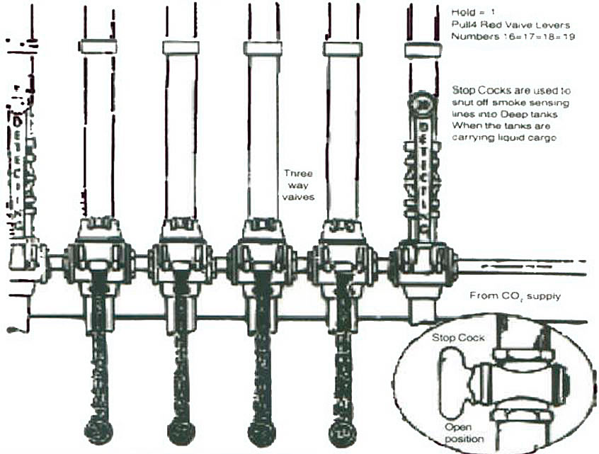
The carbon dioxide system consists of bottles of CO2 with a gang release arrangement and a pipe to the engine room distribution nozzles via master valve.
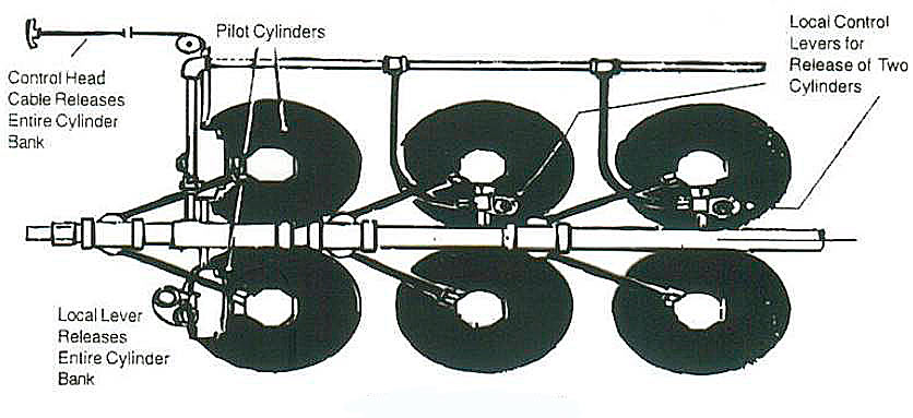
The CO2 system is used if a fire is severe enough to force evacuation of the engine room. An alarm button sounds an alarm as the CO2 cabinet s opened and in some ships there is also a stop for the engine button fans incorporated. Before releasing the CO2, personnel must be counted and the engine room must be in a shutdown condition with all openings and vent flaps closed. It is a requirement that 85 percent of the required quantity gas is released into the space within two minutes of operating the actuating handle.
In the system shown, the actuating handle opens an operating bottle of CO2 and the gas fro this pushes down the piston to release the other bottles. To avoid sticking, all the handles must be in good alignment. The bottle valves may be in the quick-release type where the combined sea/bursting disc is pierced by a cutter. The latter is hollow for passage of liquid CO2 to the discharge pipe.
Bottle pressure is normally about 52 bar (750 lb/in2) but this varies with temperature. Bottles should not be stored where the temperature is likely to exceed 55 °C. The seal/bursting discs are designed to rupture spontaneously at pressures of 177 bar produced by a temperature of about 60 °C. The master valve prevents CO2 released in this way from reaching the engine room and the relief disperses it safely on the manifold.
Rapid injection of CO2 is necessary to combat an engine room fire that has attained such magnitude that the space has to be vacated.
This is the reason for the rule 85 percent of the gas must be released within two minutes. The quantity of gas carried (a) must be sufficient to give a free gas volume equal to 40 percent of the volume of the space except where the horizontal casing area is less than 40 percent of the general area of the space except the horizontal casing area volume of air receivers may have to be taken into consideration.
The closing of all engine room openings and vent flaps will prevent entry of air to the space. All fans and pumps for fuel, can be shut down remotely as these valves can cover less than 40 percent of the general area of the space, or (b) must give a free air on fuel pipes from fuel service and storage tanks.
CO2 bottles are of solid drawn steel, hydraulically tested to 288 bars. The contents are checked by weighing or by means of radioactive level indicator. Recharging is necessary if there is a 10 percent weight loss.
Pipe work is of solid drawn mild steel, galvanized for protection against corrosion. The siphon tube in the bottle ensures that liquid is discharged from the bottles. Without the siphon tube the CO2 would evaporate from the surface and taking latent heat, would cause the remaining CO2 in the bottles to freeze.
Pressure vessels
Storage pressure for bulk CO2 is 21 bars and the temperature maintained in the bottles is –17 °C. A suitable steel for this temperature would be probably contain 3 1/2 percent nickel. Nickel used for low temperature steels reduces the coefficient of expansion and resultant thermal stress. The pressure vessels are constructed to Lloyds Class I standard.
Two refrigeration units, each capable of maintaining the required temperature, are provided. Failure of one unit causes automatic starting of the other. Failure is indicated by alarm.
Vessels are safeguarded against abnormal pressure increase by relief valves set to 24,5 bar. The discharge from these valves is piped away from the CO2 storage space to a safe area. Relief valves set to the higher figure of 27 bars are also fitted and arranged for discharge into the space to extinguish a local fire causing the pressure rise. The discharge line has a relief valve set to 35 bar.
Continuous contents monitoring is provided by a remote electrical gauge. A stand-by indicator is required in addition and provided by a vertical, external uninsulated pipe, which can be filled with liquid CO2 to the vessel level, by opening one valve. Liquid level is shown by frosting or by a radio-active device as used for CO2 bottles.
Isolating valves, are of the bellows sealed globe valve. The main CO2 discharge line is sensed for pressure so that release of gas is indicated by an alarm.
Halon system – BTM/BCF
These are only permitted in machinery spaces, pump rooms and car decks for vehicles NOT carrying cargo.
As for CO2, all ventilation fans have to be stopped. BCF and BTM work by a fast chemical inhibition of the flame and NOT by smothering. It must be fully discharge within 20 seconds. The discharge nozzles shall permit a uniform distribution but must not endanger personnel engaged in maintenance of machinery or using normal access ladders.
| Quantity for Cargo Space | Minimum | Maximum | % Gross Volume |
| Halon 1301 BTM | 5 % | 7 % | |
| Halon 1211 BCF | 5 % | 5,5 % | |
| Quantity for Machinery Space | Minimum | Maximum | % Gross Volume |
| Halon 1301 BTM | 4,25 % | 7 % | |
| Halon 1211 BCF | 4,25 % | 5,5 % |
Inert gas system
Principally used in tankers for the protection of cargo tanks carrying volatile cargoes.
The plant must be able to produce and:
- Supply to tanks Inert Gas with O2 content not exceeding 5 %.
- Supply to tank at a capacity of at least 125% of maximum cargo discharge capacity.
- Maintain a positive pressure of at least 100 mm W. G.
Low expansion foam system
Low expansion foam systems are used in Engine Rooms and Boiler Rooms. The foam system in general used today on board ships are of the “mechanical foam” type. By this, we mean the mixing of a foam-making liquid with water in the ratio of about three percent to five percent and by violent agitation in the presence of air bubbles in the top skin of the foam. The compound used for making mechanical foam usually has protein base. The low expansion foam has an expansion ratio in the region of 3:1 to 15:1.
Mechanical Foam Installation: Self-contained Pressure Type, two tanks are used containing fresh water foam-making liquid respectively. The water is released or ejected by the released of CO2 or Nitrogen from storage bottles, and on its passage across an “induction” fitting draws the required proportion of foam-making liquid from the second tank. The mixture then flows through the pipes to the machinery and boiler spaces where it passes through special foam-making fittings where it is agitated with the necessary air for the formation of foam, prior to its discharge via the foam spreaders. By the addition of extra CO2 or nitrogen compound, additional protection can be had; but it must be remembered that the water to fill the storage tank must come from the source external to the water space being protected, for example, the emergency fire pump. To cover the areas to be protected, 152 mm (6 inches) depth of foam must be available.
Mechanical Foam Installation: Pump Type, the foam making liquid is stored in the tank with connections to a large bore water main. When the water supply which must have connection to the emergency fire pump, is pressurized the foam-making liquid is include into the system by the reduction in pressure, resulting from water flowing through a venturi. The mixture is then carried to a foam-making fitting and the foam generated therein is distributed from open-ended pipes. A hand foam distributor may also be used by attaching a hose and a special eductor (“one that leads out” or “draw out”)foam-making nozzle into the main distribution line. Similar foam-making nozzles of the portable type which can be coupled directly to the fire main, are also available. Diagram Arrangement of Automatic Foam Compound Induction System. This system has an automatic inductor unit placed in the suction line to the fire pump. A small proportion of the water discharged from the pump is directed into the inductor unit to supply the inductor jet. The venturi effect of the jet creates a vacuum in the inductor port which draws in foam in the foam compound from the tank. The solution of water and compound is then discharge into the fire pump suction line.
The induction of this solution is controlled by sensing the flow of water in the suction line, the sensor operating a metering valve which increases the flow of foam compound as the water flow in the main increases, and vise versa, in the desired ratio. The air vent and supply valves are linked together so that both valves open simultaneously, thus positively preventing in advertent malfunction in the operation. To operate the system it is necessary to operate the combined air and foam compound cocks and then start the fire pump. The automatic induction unit then varies in accordance with the demand, the amount of compound required.
Diagrammatic Arrangement of Automatic Foam Compound Injection System in which a foam-compound pump is added. This pump draws compound from the tank and delivers it to the automatic induction unit, which controls the amount of compound injected by mechanically sensing the main water flow. The tank and pump(s) are placed in some convenient space outside the space to be protected, allowing due care for convenience of the operation and the frictional losses and full piecework. After use, all systems must be flushed through with fresh water particularly containing automatic inductor units, as these can “gum-up” if left.
Read also: How to Prevent Fire and Explosion or How to Minimize Effects of it
Medium expansion foam system
As with the High Expansion Foam, the medium expansion is not found to any great extent on board ships. The expansion ratio is in the order of 15:1 to 150:1 and its distribution is usually by hand applicators, the water supply coming from the fire main and the foam concentrate from portable drums. An inline inductor, to which the form concentrate supply and fire main are connected, ensures that a solution of correct proportions is delivered to the applicator for converting into foam of the correct expansion ratio.
This type foam has been accepted by IMO Sub-Committee on Fire Protection for use on the decks of tankers.
High expansion foam system
This type of foam, which has an expansion of up to 1500:1, is also available for both fixed systems (excluding deck foam systems on tankers) and for portable systems. Its generation and method of distribution are different from that of low expansion foam systems. It has not yet been used to any great extent in shipping but does have potential.
The production of Hi Ex foam necessities the use of a special foam generator which consist basically of a power driven fan, a net of gauze, a supply of Hi Ex foam compound, and a means to spray the water-foam solution evenly over the net.
The solution is uniformly sprayed over the net, usually made of nylon and air is blown through it. When external shutters are opened, foam of uniform size and having an expansion ratio of up to 1 500:1 is produced and ducted away to the protected space. The foam is tough and persistent and an excellent insulator and absorber of radiant heat. When the foam reaches the fire, each unit of water in the foam is turned into approximately 1 700 units of steam. The resulting atmosphere now contains less than the percentage required to sustain burning. At the same time, the surrounding foam prevents access of further oxygen to the fire. Ducting, by necessity necessity, has to be large cross section. Hi Ex foam has also tendency to break down when passing through long lengths of ducting. A froth generating capacity that allows a rise level of 1 meter (3,28 feet) per minute is generally regarded as acceptable.
Latest development in the use of such foam include the possibility of inerting the cargo spaces of oil tankers and combination carriers during water washing procedures to reduce the risk of explosion. Such application is still only in the development stage as is the use of Inert Gas – Definition and Pronunciationinert gas in producing the foam.

- The international group of liquefied natural gas importers (GIIGNL). LNG custody transfer handbook / 6th Edition: 2020-
2021.
- American Gas Association, Gas Supply Review, 5 (February 1977).
- ©Witherby Publishing Group Ltd. LNG Shipping Knowledge / 3rd Edition: 2008-2020.
- CBS Publishers & Distributors Pvt Ltd. Design of LPG and LNG Jetties with Navigation and Risk Analysis / 4th Edition.
- NATURAL GAS PROCESSING & ITS ENERGY TRANSITION ROLE: LNG, CNG, LPG & NGL Paperback – Large Print, November 14,
2023.
- American Gas Association, Gas Supply Review, 5 (February 1977).
- The Society of International Gas Tanker and Terminal Operators (SIGTTO). Ship/Shore Interface / 1st Edition, 2018.
- Federal Power commission, Trunkline LNG Company et al., Opinion No. 796-A, Docket No s. CP74-138-140 (Washington, D. C.:
Federal Power Commission, June 30, 1977).
- Federal Power Commission, Final Environmental Impact Statement Calcasieu LNG Project Trunkline LNG Company
Docket No. CP74-138 et al., (Washington, D. C.: Federal Power Commission, September 1976).
- Federal Power Commission, «FPC Judge Approves Importation of Indonesia LNG».
- Federal Power Commission, «Table of LNG imports and exports for 1976», News Release, June 3, 1977, and Federal Energy
Administration, Monthly Energy Review, March 1977.
- Office of Technology Assessment LNG panel meeting, Washington, D. C., June 23, 1977.
- Socio-Economic Systems, Inc., Environmental Impact Report for the Proposed Oxnard LNG Facilities, Safety, Appendix
B (Los Angeles, Ca.: Socio-Economic Systems, 1976).
- «LNG Scorecard», Pipeline and Gas Journal 203 (June 1976): 20.
- Dean Hale, «Cold Winter Spurs LNG Activity»: 30.