This article contains basic information about arrangement of the LNG/LPG ship carrying natural gas.
Segregation of the cargo area
Hold spaces are to be segregated from machinery and boiler spaces, accommodation spaces, service spaces and control stations, chain lockers, drinking and domestic water tanks and from stores. Hold spaces should be located forward of machinery spaces of category A, other than those deemed necessary by the Society for the safety or navigation of the ship.
Where cargo is carried in a cargo containment system not requiring a secondary barrier, segregation of hold spaces from spaces referred above or spaces either below or outboard of the hold spaces may be effected by cofferdams, fuel oil tanks, or a single gastight bulkhead of all welded construction forming an A-60 class division. A gas-tight A-0 class division is satisfactory if there is no source of ignition or fire hazard in the adjoining spaces.
Where cargo is carried in a cargo containment system requiring a secondary barrier, segregation of hold spaces from spaces referred above or spaces either below or outboard of the hold spaces which contain a source of ignition or fire hazard is to be effected by cofferdams or fuel oil tanks. If there is no source of ignition or fire hazard in the adjoining space, segregation may be by a single A-0 class division which is gas-tight.
When cargo is carried in a cargo containment system requiring a secondary barrier:
- at temperatures below -10 °C, hold spaces are to be segregated from the sea by a double bottom;
- and temperatures below -55 °C, the ship is also to have a longitudinal bulkhead forming side tanks.
Any piping system which may contain cargo or cargo vapour is:
- to be segregated from other piping systems, except where inter-connections are required for cargo related operations, such as purging, gas freeing or inerting. In such cases precautions are to be taken to ensure that cargo or cargo vapour cannot enter such other piping systems through the interconnections;
- except as provided in “Use of Cargo as Fuel on Gas Tankers”LNG as fuel, not to pass through any accommodation space, service space or control station or through a machinery space other than a cargo pump room or cargo compressor space;
- to be connected into the cargo containment system directly from the open deck, except that pipes installed in a vertical trunk-way or equivalent may be used to traverse void spaces above a cargo containment system and except that pipes for drainage, venting or purging may traverse cofferdams;
- except for bow or stern loading and unloading arrangements in accordance with “Bow or stern loading and unloading arrangements”, and emergency cargo jettisoning piping systems in accordance (see below), and except in accordance with “Use of Cargo as Fuel on Gas Tankers”LNG as fuel, to be located in the cargo area above the open deck;
- and except for athwartship shore connection piping not subject to internal pressure at sea or emergency cargo jettisoning arrangements, to be located inboard of the transverse tank location requirement of “Location of cargo tanks”Ship Survivability and Cargo Tanks Placement.
Any emergency cargo jettisoning piping system should comply with list above as appropriate and may be led aft externally to accommodation spaces, service spaces or control stations or machinery spaces, but are not to pass through them. If an emergency cargo jettisoning piping system is permanently installed a suitable means of isolation from the cargo piping is to be provided within the cargo area.
Arrangements are to be made for sealing the weather decks in way of openings for cargo containment systems.
Hold spaces are to be separated from each other by single bulkheads. Due consideration is to be given to the steel selection of the bulkheads considering the lowest temperature they may be exposed to during service. Where cofferdams are used instead of single bulkheads, they may be used as ballast tanks subject to special approval by the Society.
Accommodation, service and machinery spaces and control stations
No accommodation space, service space or control station is to be located within the cargo area. The bulkhead of accommodation spaces, service spaces or control stations which face the cargo area is to be located so as to avoid the entry of gas from the hold space to such spaces through a single failure of a deck or bulkhead on a ship having a containment system requiring a secondary barrier.
In order to guard against the danger of hazardous vapours, due consideration is to be given to the location of air intakes and openings into machinery spaces, accommodation spaces, service spaces and control stations in relation to cargo piping, cargo vent systems and machinery space exhausts from gas burning arrangements.
Access through doors, gastight or otherwise, is not permitted from a gas safe space to a gas dangerous space, except for access to service spaces forward of the cargo area through air locks as permitted by “Air locks” when accommodation spaces are aft.
Entrances, air inlets and openings to accommodation spaces, service spaces, machinery spaces and control stations shall not face the cargo area. They are to be located on the end bulkhead not facing the cargo area or on the outboard side of the superstructure or deckhouse at a distance of at least Lc/25 but not less than 3 m from the end of the superstructure or deckhouse facing the cargo area. This distance, however, need not exceed 5 m. Windows and side scuttles facing the cargo area and on the sides of the superstructures or deckhouses within the distance mentioned above are to be of the fixed (non-opening) type.
Wheelhouse windows may be non-fixed and wheelhouse doors may be located within the above limits so long as they are so designed that a rapid and efficient gas and vapour tightening of the wheelhouse can be ensured. For ships dedicated to the carriage of cargoes which have neither flammable nor toxic hazards, the Society may approve relaxations from the above requirements.
Side scuttles in the shell below the uppermost continuous deck and in the first tier of a superstructure or deckhouse are to be of the fixed (non-opening) type.
All air intakes and openings into the accommodation, service and control station spaces are to be fitted with closing devices. For toxic gases they are to be operated from inside the space.
Compliance with other relevant paragraphs of the Code and in particular with “Cargo Temperature Control and Cargo Vent Systems”Pressure relief systems and “Mechanical Ventilation in The Cargo Area on Liquefied gas tankers”Mechanical Ventilation where applicable would also ensure compliance with this paragraph. Air outlets are subject to the same requirements as air inlets and air intakes. This interpretation also applies to paragraphs below and “Cargo Temperature Control and Cargo Vent Systems”Pressure relief systems.
Doors facing the cargo area or located in prohibited zones in the sides are to be restricted to stores for cargo-related and safety equipment, cargo control stations as well as decontamination showers and eye wash.
The requirement for fitting air intakes and openings with closing devices operable from inside the space in ships intended to carry toxic products shall apply to spaces which are used for:
- ship’s radio and main navigating equipment;
- cabins;
- mess rooms;
- toilets;
- hospitals;
- galleys etc.,
but shall not apply to:
- engine room casings;
- deck stores;
- steering gear compartments;
- workshops etc.
The requirement does also not apply to forecastle stores and to cargo control rooms located within the cargo areas. When internal closing is required, this shall include both ventilation intakes and outlets. The closing devices shall give a reasonable degree of gas tightness. Ordinary steel fire-flaps without gaskets/seals shall normally not be considered satisfactory.
Access to forecastle spaces containing sources of ignition may be permitted through doors facing cargo area provided the doors are located outside hazardous areas as defined in IEC Publication 60092-502.
Cargo pump rooms and cargo compressor rooms
Cargo pump rooms and cargo compressor rooms are to be situated above the weather deck and located within the cargo area unless specially approved by BKI. Cargo compressor rooms are to be treated as cargo pump rooms for the purpose of fire protection according to, according to Regulation II-2/9.2.4 of the 1974 SOLAS Convention see also Rules for Machinery Installations (Part 1, Vol. III) Sec. 12.
When cargo pump rooms and cargo compressor rooms are permitted to be fitted above or below the weather deck at the after end of the aftermost hold space or at the forward end of the foremost hold space, the limits of the cargo area are to be extended to include the cargo pump rooms and cargo compressor rooms for the full breadth and depth of the ship and deck areas above those spaces.
Where the limits of the cargo area are extended above, the bulkhead which separates the cargo pump rooms and cargo compressor rooms from accommodation and service spaces, control stations and machinery spaces of category A is to be so located as to avoid the entry of gas to these spaces through a single failure of a deck or bulkhead.
Where pumps and compressors are driven by shafting passing through a bulkhead or deck, gastight seals with efficient lubrication or other means of ensuring the permanence of the gas seal are to be fitted in way of the bulkhead or deck.
Arrangements of cargo pump rooms and cargo compressor rooms are to be such as to ensure safe unrestricted access for personnel wearing protective clothing and breathing apparatus, and in the event of injury to allow unconscious personnel to be removed. All valves necessary for cargo handling are to be readily accessible to personnel wearing protective clothing. Suitable arrangements shall be made to deal with drainage of pump and compressor rooms.
When cargo pump rooms or compressor rooms are permitted to be fitted at the after end of the aftermost hold space the bulkhead which separates the cargo pump rooms or compressor rooms from accommodation and service spaces, control stations and machinery spaces of category A are to be so located as to avoid the entry of gas to these spaces through a single failure of a deck or bulkhead. The same condition is also to be satisfied when cargo pump rooms and compressor rooms, fitted within the cargo area, have a bulkhead in common with accommodation and service spaces, control stations and machinery spaces of category A.
Cargo control rooms
Any cargo control room is to be above the weather deck and may be located in the cargo area. The cargo control room may be located within the accommodation, service or control station spaces provided the following conditions are complied with:
- the cargo control room is a gas safe space;
- and if the entrance complies with “Accommodation, service and machinery spaces and control stations”, the control room may have access to the spaces described above;
- if the entrance does not comply with “Accommodation, service and machinery spaces and control stations “, the control room shall have no access to the spaces described above and the boundaries to such spaces shall be insulated to “A-60” Class integrity.
If the cargo control room is designed to be a gas safe space, instrumentation shall, as far as possible, be by indirect reading systems and shall in any case be designed to prevent any escape of gas into the atmosphere of that space. Location of the gas detector within the cargo control room will not violate the gas safe space if installed in accordance with “Gas detection requirements”Cargo Tank Instrumentation on Gas Tankers.
If the cargo control room for ships carrying flammable products is a gas dangerous space, sources of ignition are to be excluded. Consideration is to be paid to the safety characteristics of any electrical installations.
Access to spaces in the cargo area
Visual inspection shall be possible of at least one side of the inner hull structure without the removal of any fixed structure or fitting. If such a visual inspection, whether combined with those inspections required in “Cargo containment system of gas vessel”Secondary barrier or “Cargo containment system of gas carrier”Construction and testing or not, is only possible at the outer face of the inner hull, the inner hull shall not be a fuel-oil tank boundary wall.
Inspection of one side of any insulation in hold spaces shall be possible. If the integrity of the insulation system can be verified by inspection of the outside of the hold space boundary when tanks are at service temperature, inspection of one side of the insulation in the hold space need not be required.
Arrangements for hold spaces, void spaces and other spaces that can be considered gas dangerous and cargo tanks are to be such as to allow entry and inspection of any such space by personnel wearing protective clothing and breathing apparatus and in the event of injury to allow unconscious personnel to be removed from the space and to comply with the following:.
a) access is to be provided:
- to the cargo tanks direct from the open deck;
- through horizontal openings, hatches or manholes the dimensions of which are to be sufficient to allow a person wearing a breathing apparatus to ascend or descend any ladder without obstruction, and also to provide a clear opening to facilitate the hoisting of an injured person from the bottom of the space. The minimum clear opening is to be not less than 600 mm by 600 mm;
- and through vertical openings, or manholes providing passage through the length and breadth of the space, the minimum clear opening of which is to be not less than 600 mm by 800 mm at a height of not more than 600 mm from the bottom plating unless gratings or other footholds are provided.
б) The dimensions referred above may be decreased if the ability to transverse such openings or to remove an injured person can be proved to the satisfaction of the Society.
в) The requirements do not apply to those spaces. Such spaces are to be provided only with direct or indirect access from the open weather deck not including an enclosed gas safe space.
Access from the open weather deck to gas safe spaces is to be located in a gas safe zone at least 2,4 m above the weather deck unless the access is by means of an air lock in accordance with “Air locks”.
Designated passage ways below and above cargo tanks are to have at least the cross sections as required above.
For the purpose described above the following applies:
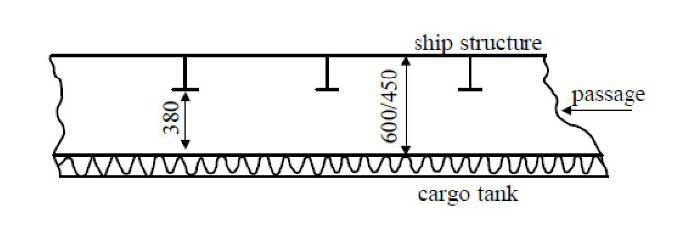
1 Where the surveyor requires to pass between the surface to be inspected, flat or curved, and structural elements such as deckbeams, stiffeners, frames, girders etc., the distance between that surface and the free edge of the structural elements is to be at least 380 mm. The distance between the surface to be inspected and the surface to which the above structural elements are fitted, e.g. deck, bulkhead or shell is to be at least 450 mm in case of a curved tank surface (e.g. in case of type C-tank) or 600 mm in case of a flat tank surface (e.g. in case of type A-tank) (see Pic. 1).
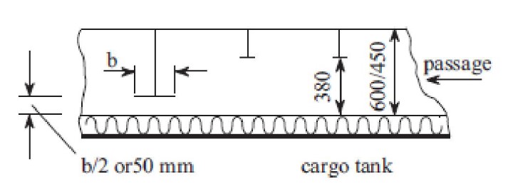
Where the Surveyor does not require to pass between the surface to be inspected and any part of the structure, for visibility reasons the distance between the free edge of that structural element and the surface to be inspected is to be at least 50 mm or half the breadth of the structure’s face plate, whichever is the larger (see Pic. 2).
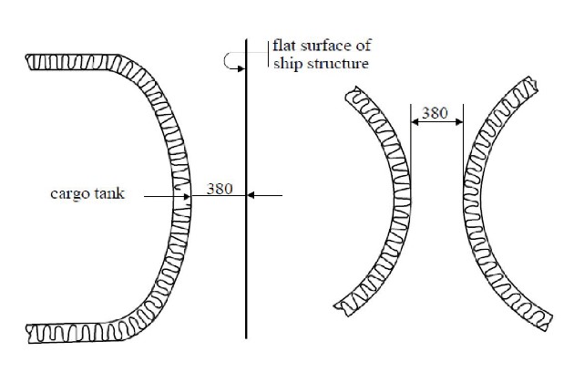
If for inspection of a curved surface the Surveyor requires to pass between that surface and another surface, flat or curved, to which no structural elements are fitted, the distance between both surfaces is to be at least 380 mm (see Pic. 3). Where the surveyor does not require to pass between a curved surface and another surface, a smaller distance than 380 mm may be accepted taking into account the shape of the curved surface.
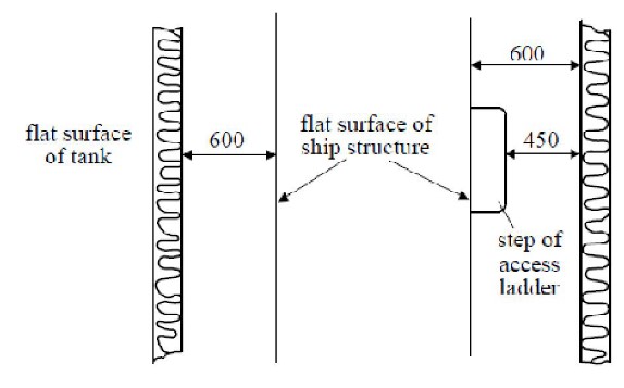
If for inspection of an approximately flat surface the Surveyor requires to pass between two approximately flat and approximately parallel surfaces, to which no structural elements are fitted, the distance between those surfaces are to be at least 600 mm (see Pic. 4).
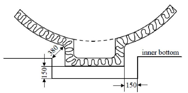
The minimum distances between a cargo tank sump and adjacent double bottom structure in way of a suction wells are not to be less than shown in Pic. 5. If there is no section well, the distance between the cargo tank sump and the inner bottom is not to be less than 50 mm.
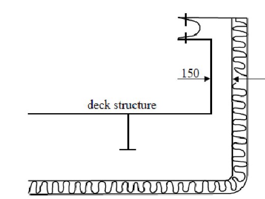
The distance between a cargo tank dome and deck structures is not to be less than 150 mm (see Pic. 6).
If necessary for inspection fixed or portable staging is to be installed. This staging is not to impair the distances required under described above.
If fixed or portable ventilation ducting has to be fitted in compliance with “Mechanical Ventilation in The Cargo Area on Liquefied gas tankers”Spaces not normally entered such ducting is not to impair the distances required under described above.
For the purpose of subparagraph “Access to spaces in the cargo area” the following applies:
- The term “minimum clear opening of not less than 600×600 mm” means that such openings may have corner radii up to 100 mm maximum.
- The term “minimum clear opening of not less than 600×800 mm” includes also an opening of the following size:
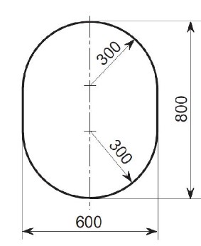
Circular access openings in type C cargo tanks are to have diameters of not less than 600 mm.
Air locks
An air lock is permitted only between a gas dangerous zone on the open weather deck and a gas safe space and is to consist of two steel doors substantially gastight spaced at least 1,5 m but not more than 2,5 m apart.
The doors are to be self-closing and without any holding back arrangements. An audible and visual alarm system to give a warning on both sides of the air lock is to be provided to indicate if more than one door is moved from the closed position.
In ships carrying flammable products electrical equipment which is not of the certified safe type in spaces protected by air locks should be de-energized upon loss of over-pressure in the space (see also ).
Electrical equipment which is not of the certified safe type for maneuvering, anchoring and mooring equipment as well as the emergency fire pumps should not be located in spaces to be protected by air locks.
The following means for monitoring overpressure in spaces protected by air-locks are considered acceptable alternatives to differential pressure sensing devices in spaces having a ventilation rate not less than 30 air changes per hour:
- .1monitoring of current or power in the electrical supply to the ventilation motors;
- or air flow sensors in the ventilation ducts.
In spaces where the ventilation rate is less than 30 air changes per hour and where one of the above alternatives is fitted, in addition to the alarms required as described above,arrangements are to be made to de-energize electrical equipment which is not of the certified safe type, if more than one air lock door is moved from the closed position.
The air lock space is to be mechanically ventilated from a gas safe space and maintained at an over-pressure to the gas dangerous zone on the open weather deck.
The air lock space is to be monitored for cargo vapour. Subject to the requirements of the International Convention on Load Lines, 1966, the door sill is not to be less than 300 mm in height.
Bilge, ballast and fuel oil arrangements
Where cargo is carried in a cargo containment system not requiring a secondary barrier, hold spaces are to be provided with suitable drainage arrangements not connected with the machinery space. Means of detecting such leakage are to be provided.
Where there is a secondary barrier, suitable drainage arrangements for dealing with any leakage into the hold or insulation spaces through adjacent ships structure are to be provided. The suction is not to be led to pumps inside the machinery space. Means of detecting such leakage are to be provided.
The hold or interbarrier space of Type A independent tanks shall be provided with a drainage system suitable for handling liquid cargo in the event of cargo tank leakage or rupture. Such arrangements shall provide for the return of any cargo leakage to the liquid cargo piping.
Arrangement referred above shall be provided with removable spool pieces.
In case of internal insulation tanks, means of detecting leakage and drainage arrangements are not required for interbarrier spaces and spaces between the secondary barrier and the inner hull or independent tank structure which are completely filled by insulation material complying with “Cargo containment system of gas vessel”Materials.
Ballast spaces, including wet duct keels used as ballast piping, fuel-oil tanks and gas-safe spaces may be connected to pumps in the machinery space. Dry duct keels with ballast piping passing through, may be connected to pumps in the machinery spaces, provided the connections are led directly to the pumps and the discharge from the pumps led directly overboard with no valves or manifolds in either line which could connect the line from the duct keel to lines serving gas safe spaces. Pump vents are not be open to machinery spaces.
Bow or stern loading and unloading arrangements
Subject to the requirements of this article, cargo piping may be arranged to permit bow or stern loading and unloading. Bow or stern loading and unloading lines which are led past accommodation spaces, service spaces or control stations shall not be used for the transfer of products requiring a Type 1G ship. Bow or stern loading and unloading lines shall not be used for the transfer of toxic products, unless specifically approved by BKI.
Portable arrangements shall not be permitted. In addition to the requirements of “Piping System of pressure vessels on gas tankers”Piping systems the following provisions apply to cargo piping and related piping equipment:
- Cargo piping and related piping equipment outside the cargo area are to have only welded connections. The piping outside the cargo area shall run on the open deck and shall be at least 760 mm in board except for the athwartships shore connection piping. Such piping shall be clearly identified and fitted with a shut-off valve at its connection to the cargo piping system within the cargo area. At this location, it shall also be capable of being separated by means of a removable spool piece and blank flanges when not in use.
- The piping is to be full penetration butt welded, and fully radiographed regardless of pipe diameter and design temperature. Flange connections in the piping are only permitted within the cargo area and at the shore connection.
- Arrangements are to be made to allow such piping to be purged and gas-freed after use. When not in use, the spool pieces shall be removed and the pipe ends to be blank-flanged. The vent pipes connected with the purge are to be located in the cargo area.
Entrances, air inlets and openings to accommodation spaces, service spaces, machinery spaces and control stations shall not face the cargo shore connection location of bow or stern loading and unloading arrangements. They shall be located on the outboard side of the superstructure or deckhouse at a distance of at least Lc/25 but not less than 3 m from the end of the superstructure or deckhouse facing the cargo shore connection location of the bow or stern loading and unloading arrangements.
This distance, however, need not exceed 5 m. Side scuttles facing the shore connection location and on the sides of the superstructure or deckhouse within the distance mentioned above shall be of the fixed (non-opening) type. In addition, during the use of the bow or stern loading and unloading arrangements, all doors, ports and other openings on the corresponding superstructure or decks and deck houses shall be closed. Where in case of small ships compliance with “Accommodation, service and machinery spaces and control stations” and this paragraph is not possible, the Society may approve relaxations from the above requirements.
Deck openings and air inlets to spaces within distances of 10 m from the cargo shore connection location shall be kept closed during the use of bow or stern loading or unloading arrangements.
Electrical equipment within a zone of 3 m from the cargo shore connection location shall be in accordance with “Fire protection and Fire extinction on Liquefied Gas Carriers”Electric Installations. Fire-fighting arrangements for the bow or stern loading and unloading areas are to be in accordance with “Water spray system”Fire protection and Fire extinction on Liquefied Gas Carriers and “Dry chemical powder fire extinguishing systems”Fire protection and Fire extinction on Liquefied Gas Carriers.
Means of communication between the cargo control station and the shore connection location shall be provided and, if necessary, certified safe.