Explore the advanced solutions offered by LPG reliquefaction plants and boil-off control systems. Enhance your understanding of their role in preserving LPG integrity during storage and transportation, mitigating environmental impact, and maintaining operational excellence in the oil and gas industry.
- LPG Reliquefaction Plant and Boil-Off Control
- Cargo compressors and associated equipment
- Reciprocation compressors
- Screw compressors
- Compressor suction liquid separator
- Carqo compressor suction gas cooling
- Purge gas condenser
- LNG Reliquefaction Plant and Boil-off Control Systems
- LNG boil-off and vapour handling systems
- LNG compressor (vapour return and fuel gas)
- Gas combustion units (GCU)
- LNG reliquefaction
- Inert Gas and Nitrogen Systems
- Inert gas generators
- Nitrogen production on ships
- Pure nitrogen from the shore
- Electrical Equipment
- Cargo Instrumentation
- Liquid level instrumentation
- Magnetic level transmitters
- Level alarm and automatic shutdown systems
- Pressure and temperature monitoring
- Gas detection system
- LNG custody transfer measurement systems (CTMS)
- Integrated system
- Calibration
- Ship/Shore Links
Learn how the efficiency and reliability of LPG reliquefaction plants and boil-off control systems, and also how these technologies optimize liquefied petroleum gas storage, transportation, and utilization, ensuring minimal waste and maximum safety.
LPG Reliquefaction Plant and Boil-Off Control
Except for fully-pressurised gas carriers, a means is usually provided to control cargo vapour pressure in cargo tanks during loading and on passage. In the case of LPG and chemical gas carriers, a reliquefaction plant is fitted for this purpose. This equipment is designed to perform the following primary functions:
- To cool-down the cargo tanks and associated pipelines before loading;
- to reliquefy the cargo vapour generated by flash evaporation, liquid displacement and boil-off during loading;
- to maintain cargo temperature and pressure within prescribed limits while at sea by reliquefying the boil-off vapour.
Cargo compressors and associated equipment
Cargo compressors onboard gas carriers are commonly used for:
- Increasing the pressure of the vapour so that it is above its SVP and can, therefore, be condensed by a suitable cooling medium within a reliquefaction plant;
- moving vapour through the cargo system;
- increasing the pressure of the vapour so that it can be used within the propulsion system.
On board LPG carriers the compressors are primarily used as part of the reliquefaction plant, where most of the compressors used are of the reciprocating type.
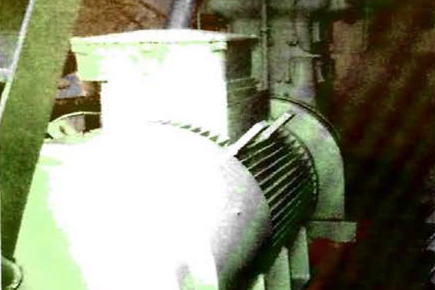
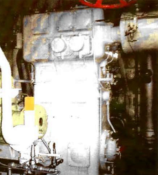
Reciprocation compressors
Ships may be fitted with oil-lubricated compressors where the cargo is in contact with the lubricant. To avoid contamination of the cargo, efficient oil separators are usually fitted in the compressor discharge lines. The lubricant inside the machine will be kept warm during operations to prevent dilution in the crankcase.
Full data on the operation of the compressors should be available from manufacturers’ handbooks.
Many ships are fitted with “oil-free” cargo compressors, where the design prevents crankcase lubricants entering the cargo cylinders.
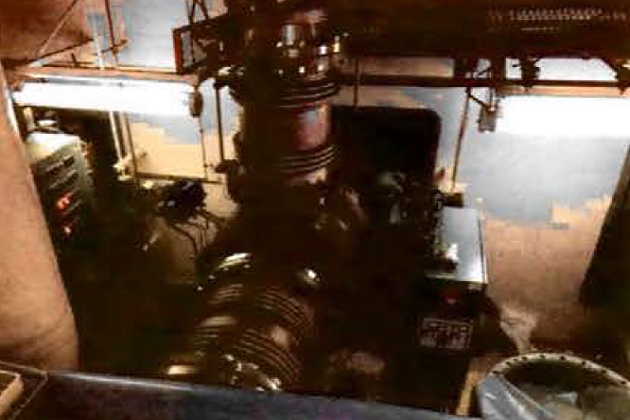
In the “Burckhardt” oil-free compressor, shown in Figure 3, sealing between the piston and cylinder wall, and between the piston rod and gland, is achieved by the use of machined labyrinths. Consequently, no lubrication is needed for those spaces in the compressor that are swept by cargo vapours.
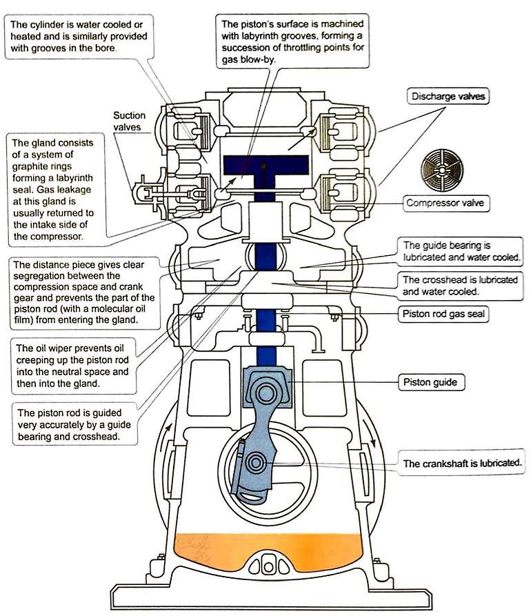
The absence of any contact at the seals limits wear and lubricating oil consumption is minimal. The oil-free side of the compressor and the lubricated crank are separated by oil scraper rings mounted on the piston rod. The rod also carries a ring that prevents any residual oil film from creeping up the rod. The distance between the crank and gland is such that the oily part of the piston rod cannot enter the oil-free gland. If any gas leaks through the gland it is returned to the suction side. The crankcase and separation space are kept under suction pressure. Where the crankshaft leaves the case it is fitted with a shaft seal operating in oil.
Capacity control of the compressor is achieved by lifting suction valves during the compression stroke. The plate lifters are normally hydraulically operated, with the fluid pressure provided by the lubricating oil pump. When the compressor is shut down the cargo vapour in the crankcase can condense, giving rise to lubricating problems. To avoid this, it is common for the crankcase to be heated when the compressor is idle. When the compressor is running, cooling will commonly be provided for the crankcase, the crossheads and the guide bearings. Normally, a closed cycle glycol water system provides for the heating when the compressor is shut down and for cooling when the compressor is running.
Read also: Properties of liquefied gases
While reciprocating compressors are primarily found within the reliquefaction system, reciprocating compressors may also be found as part of the fuel supply system to the new generation of ME-GI engines, where outlet pressures required may be in excess of 250 bar.
Screw compressors
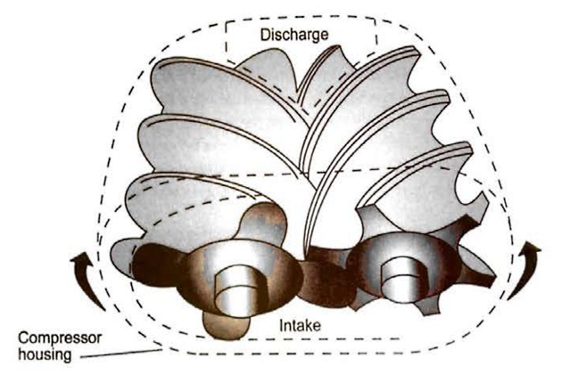
Screw compressors, for use with liquefied gas cargoes, can be dry, oil-free or oil flooded machines. In the dry machines the screw rotors do not make physical contact but are held inter-meshed and driven by external gearing. Due to leakage through the clearances between the rotors, high speeds are necessary to maintain good efficiency (typically 12 000 rpm). Figure 4 is a diagram of a typical rotor set with the common combination of four and six lobes. The lobes inter-mesh and gas is compressed in the chambers, which are reduced in size as the rotors turn. The compressor casing carries the suction and discharge ports.
The oil flooded machine relies on oil injection into the rotors and this eliminates the need for timing gears. Drive power is transmitted from one rotor to the other by the injected oil. This also acts as a lubricant and coolant. Because the rotors are sealed with oil, gas leakage is much less, so oil flooded machines can run at lower speeds (3 000 rpm). An oil separator on the discharge side of the machine removes oil from the compressed gas.
Capacity control of screw compressors can be achieved in a number of ways. The most common is the use of a sliding valve that effectively reduces the working length of the rotors. This is more efficient than suction throttling.
Compressor suction liquid separator
It is necessary to protect cargo vapour compressors against the possibility of liquid being drawn in. This can seriously damage compressors because liquid is incompressible. It is normal practice, therefore, to install a liquid separator on the compressor suction line coming in from the cargo tanks. The purpose of this separator is to reduce vapour velocity and, as a result, to allow any entrained liquid to be easily removed from the vapour stream. In case of over-filling, the separator is fitted with level sensors that set off an alarm and trip the compressor.
Carqo compressor suction gas cooling
In some cases, a condensate injection system may be fitted to the compressor suction system for use in high discharge temperatures, particularly just after start-up.
The system works by flash cooling the suction gas and normally comprises a small spray nozzle fitted upstream of the suction gas liquid separator. The injection system is usually fitted with a manual control valve and actuated isolation valve. The manual valve is used to regulate the condensate flow to keep the compressor temperatures below trip settings.
The actuated valve is typically interlocked so that it will only open if the appropriate compressor is running. Usually, it also closes the injection system automatically, in the event of the compressor stopping, to prevent liquid carry-over.
Purge gas condenser
Many reliquefaction plants are fitted with a shell and tube heat exchanger mounted above the cargo condenser. The purpose of this heat exchanger is to condense any cargo vapours that remain mixed with incondensible gases (such as nitrogen), which may have failed to condense in the main condenser. For example, commercial propane, which may have 2 % ethane in the liquid, will have up to 14 % ethane in the vapour as it is the more volatile component. On LPG carriers, the presence of ethane can cause difficulties in a conventional seawater cooled condenser.
Figure 5 shows a typical purge gas condenser system. The uncondensed gases in the main condenser are displaced into the shell of the purge condenser. Here they are subjected to the same pressure that exists in the main condenser, but at a lower condensing temperature.
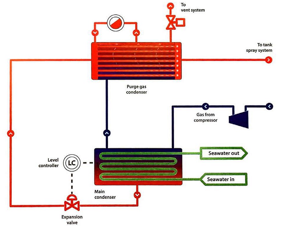
This is equivalent to the outlet temperature from the expansion valve, since the whole or part of this liquid passes through the tube side of the purge condenser. This lower condensing temperature allows cargo vapours to be condensed and incondensible gases to be purged from the top of the purge gas condenser by a pressure control system.
LNG Reliquefaction Plant and Boil-off Control Systems
As with LPG carriers, except for fully-pressurised vessels, a means will be provided to control cargo vapour pressure in the cargo tanks during cargo operations and on passage. On LNG carriers, options include:
- Vapour return to shore (loading and discharge operations), or;
- oxidising the vapours, either in:
- a. the propulsion plant (boilers, diesel engines, etc.), or
- b. a dedicated oxidiser unit (gas combustion unit (GCU)).
LNG boil-off and vapour handling systems
Boil-off vapours are produced during cool-down, loading and during the loaded and ballast voyages. Typically, the low duty (LD) compressor handles the boil-off while on passage and the high duty (HD) compressor handles cargo vapours produced during cool-down and loading, returning these vapours to shore.
When a ship is at sea the LD compressor collects the BOG from a header connected to each cargo tank, passing it through a heat exchanger and into the engine room. The pipeline is jacketed from the point at which it enters the engine room or the accommodation, up to either the boiler front or dual fuel engine, depending upon the propulsion system. The annular space (between the gas pipeline and its jacket) may be either pressurised with nitrogen or exhaust ventilated with air, giving at least 30 changes per hour. The gas pipeline will, ordinarily, be purged with nitrogen before and after gas burning operations.
There are a number of automatic protective devices built into the system to ensure safe operation and these will need to be regularly inspected and maintained. Protective systems include continuous monitoring for leakage and automatic shutdown in the event of system malfunction or leak detection. These systems are described in some detail in the IGC Code, and the provisions of the IGC Code should always be complied with in deference to anything in this publication.
The compressors are provided with surge controls and other protective devices. On some compressors, liquid cargo may be used as the precooling medium, in which case a certain amount of liquid heel in the cargo tanks is required to be maintained.
LNG compressor (vapour return and fuel gas)
On LNG carriers, compressors are primarily used to:
- Send vapour back to the shore during loading operations;
- circulate warm vapour during warm up operations;
- provide a fixed flow of vapour into the propulsion system;
- provide a flow of vapour to the GCU (if fitted);
- provide a flow of vapour through a reliquefaction plant (if fitted).
Compressors used on LNG carriers are usually of the “turbo” compressor type, although multi-stage, reciprocating compressors can be found in some high pressure dual fuel engine propulsion systems.
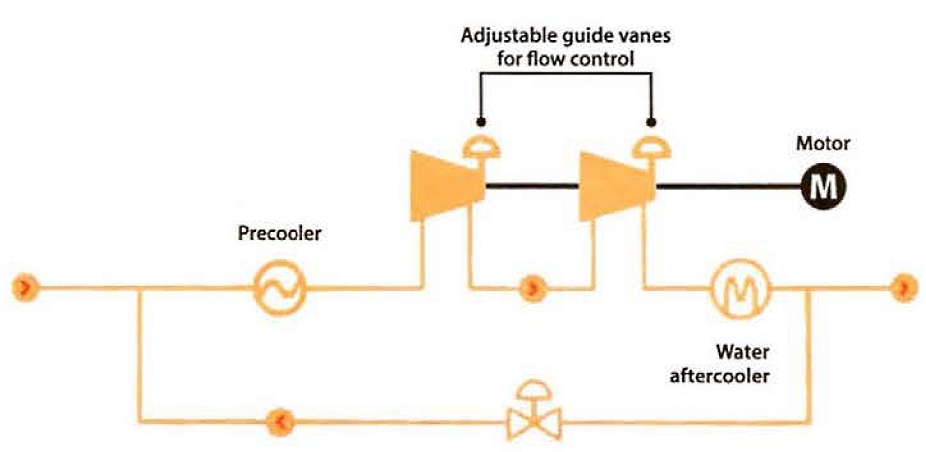
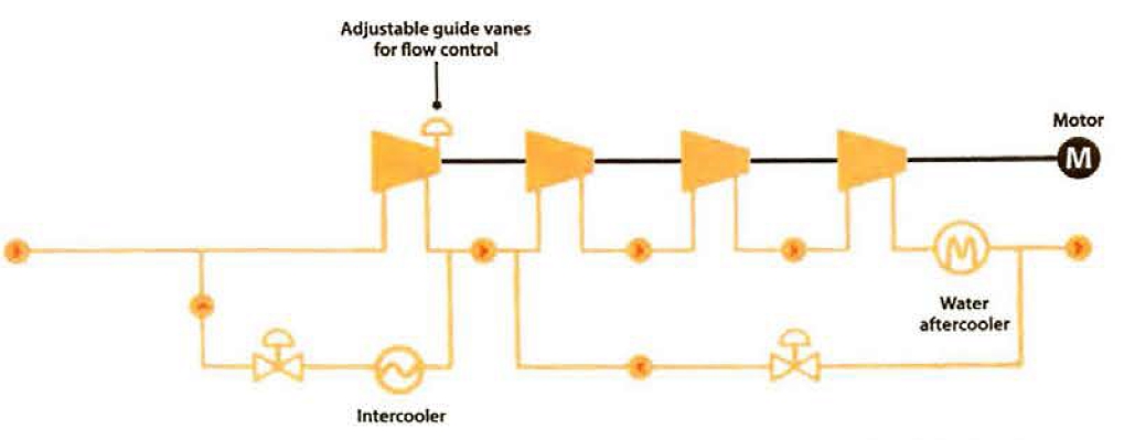
Turbo compressors
Turbo compressors consist of a rotor, which is usually mounted horizontally and connected to the driving mechanism via a gearbox. Primary capacity control is through the use of an adjustable inlet guide vane. The compressors may be fixed or variable speed, depending on the application for which they are being used. Surges, which may cause damage to the compressor, are prevented automatically by using a surge control valve to increase the flow through the compressor.
While the early era (pre-1980) LNG carriers used steam turbines to drive the compressors, modern LNG carriers use electric motors for the compressor drives.
The compressors may consist of a single or multiple stages, depending on the application:
- High duty compressor – single stage. Purpose is to move large volumes of vapour at low pressure;
- Low duty compressor – single to 6-stage. Purpose is to provide vapour at an appropriate pressure and flow rate suitable for the propulsion system. For steam LNG carriers a relatively low inlet pressure is required, so single stage compressors are used, while for low pressure, dual fuel engine systems higher inlet pressures are needed, requiring the use of 2- or 4-stage compressor arrangements. Additional stages may be also be used for various reliquefaction system designs.
Gas combustion units (GCU)
The IGC Code requires two means of cargo tank pressure control. Onboard the traditional steam LNG carrier, when there is more BOG produced than is required by the needs of the propulsion system, the total volume is fired in the boilers and any excess steam is “dumped” through a seawater cooled condenser. Provision of two boilers with a steam dump satisfies IGC Code requirements.
LNG carriers utilising internal combustion engines for propulsion depend on engine load for burning BOG and, therefore, have no comparable means to burn the excess. This change in propulsion methodology creates the need to handle BOG by other means to eliminate it being vented.
GCUs, as shown in Figure 11, have been specifically developed for the controlled and safe oxidation of BOG on LNG carriers. The GCU system is required to safely oxidise excess BOG from the cargo tanks while maintaining exhaust gas temperatures at the stack outlet below 535 °C. Although this is 50 °C below the auto-ignition temperature of methane in air, an industry standard of 450 °C has been adopted. GCU capacity is selected against the maximum BOG rate of the installed cargo tanks, with the unit capable of operating reliably across various performance modes.
The GCU illustrated comprises a twin shell oxidiser body fitted with a fully automatic burner, flame supervision scanners and high energy igniters. The integrated main gas burner and GCU has its own dedicated gas valve system, oil support burner with associated fuel oil system and fuel oil pump set.
Air is supplied by combustion/dilution air fans to support combustion and to provide cooling of the GCU. The burner and associated windbox are located at the base of the GCU.
The outer cylinder of the twin shell GCU body acts as the supporting structure for the exhaust stack and includes connections for the flame scanners, igniters and sight ports. The inner cylinder acts as the combustion chamber and, around its outer circumference, provides the path for dilution air to flow to the base of the unit, maintaining a cooling effect on the outer shell before mixing with the combustion gases.
Gas is fired with controlled combustion air and then mixed with dilution air. The dilution air is introduced above the flame, creating a turbulent mixing of the cooler dilution air with the hot gases, which acts to reduce the temperature of the flue gas to within the required temperature criteria.
An oil support burner is utilised in periods of high nitrogen/low methane content BOG firing, such as at initial start-up after loading and during tank gas-freeing operations, to ensure that a stable flame is present to oxidise any pockets of methane in the BOG.
A combination inert gas generator (IGG)/GCU is fitted on some newer LNG carriers, where the exhaust gas from the GCU is used to generate inert gas. See also point “Inert Gas and Nitrogen Systems” below.
LNG reliquefaction
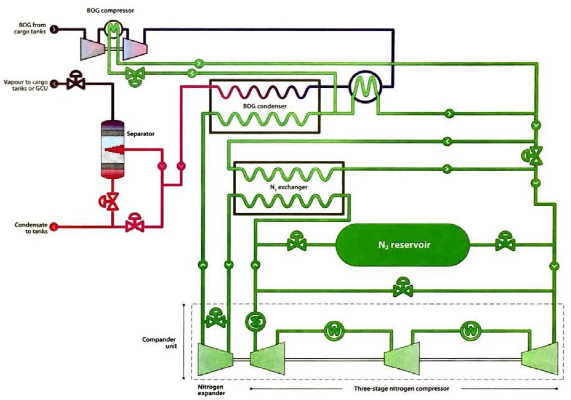
Shipboard reliquefaction is one of the key technologies that has enabled the use of slow speed diesel engine type propulsion for newer LNG carriers. The system design will take into account boil-off rate (BOR) fluctuations and composition throughout the voyage. The systems employed on LNG carriers utilise nitrogen as the refrigerant as it is non-toxic and non-flammable. An added advantage is that nitrogen can be manufactured onboard, if needed. The entire system must have sufficient redundancy to meet the requirements of the IGC Code.
Refrigeration is provided by nitrogen compression, precooling, and expansion in a simple Brayton refrigeration cycle. This is achieved with the nitrogen “compander” unit, which consists of a 3-stage compressor and a single stage expander. The amount of cold production in the process is proportional to the amount of BOG to be reliquefied and the amount of the mass circulating in the nitrogen loop.
A process flow diagram of a simplified Hamworthy reliquefaction system is shown in Figure 12. BOG is precooled by heat exchange with a small stream of reliquefied BOG (“condensate“) from the separator. The condensate is vaporised in the precooler and mixed with the incoming BOG from the cargo tanks. The precooler is provided to offset the heat ingress in the BOG piping between the cargo tanks and the reliquefaction plant. The precooler unit is also designed to collect any condensed heavy components and prevent damage to the compressors. Precooled BOG is compressed in a cryogenic 2-stage centrifugal compressor. Both compressor stages have guide vanes to control BOG flow through the compressor and to handle changes in the cargo tank BORs.
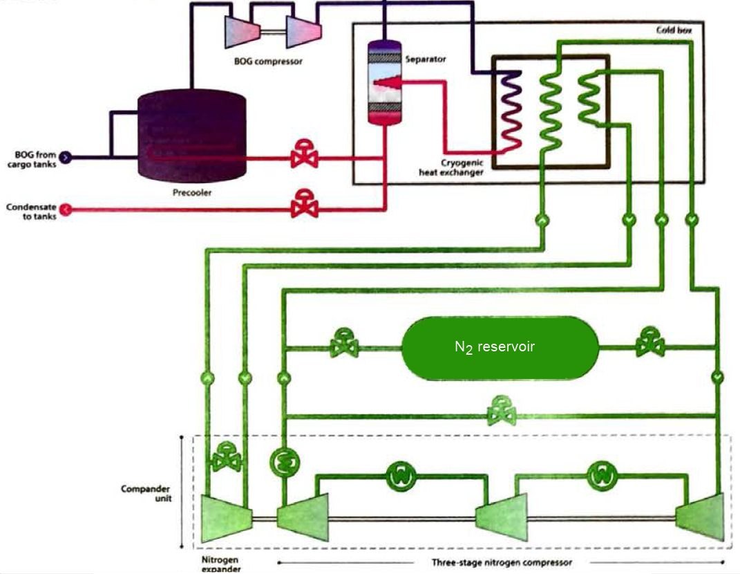
Compressed BOG enters a plate-fin heat exchanger, where it is cooled and condensed against the cold nitrogen stream. The three stream heat exchanger provides precooling of the nitrogen refrigerant stream from the compander third stage compressor discharge. Reliquefied BOG is collected in a separator to remove non-condensible gases, if present. The cryogenic heat exchanger and the separator are packaged together in an insulated cold box to minimise heat leaks into the system. In normal operation, the system operates in full reliquefaction so no vapour is removed in the separator. The pressure in the separator is normally sufficient to force the reliquefied BOG back to the cargo tanks and to the precooler.
The heat that results from nitrogen compression is removed by two freshwater intercoolers and an aftercooler. Nitrogen is precooled in the plate-fin heat exchanger and then expanded for reliquefying the BOG.
It will be interesting: Gas laws, thermodynamic principles and reliquefaction
A subsequent Hamworthy design, MK III, replaces the precooler with a preheater, warming the BOG to ambient temperatures before compressing it using a 3-stage BOG compressor. Despite the additional stage, the 3-stage BOG compressor is smaller and requires less power to drive. The higher pressure output of the 3-stage compressor allows for condensation of the BOG at a higher temperature and improved efficiency of the process.
A process flow diagram of a simplified Cryostar system is shown in Figure 13. BOG is compressed in a 2-stage centrifugal compressor. Both compressor stages have guide vanes to control BOG flow through the system. The incoming BOG is cooled by a nitrogen intercooler on the BOG compressor. Compressed BOG is then cooled in a stainless steel shell and tube heat exchanger (called the BOG de-superheater) and then condensed in a plate-fin heat exchanger. The heat exchangers are individually insulated and are not in a cold box.
In the EcoRel system the reliquefied BOG is slightly subcooled so it can be returned directly back to the tanks without requiring the separator. For higher nitrogen cargoes, the system can be operated in partial reliquefaction mode with the liquid/vapour mixture from the BOG condenser routed through the separator to remove the nitrogen-rich vapour for disposal to either the cargo tanks or the GCU.
The compressed nitrogen refrigerant is precooled in a separate plate-fin heat exchanger, called the nitrogen counter-current exchanger. After precooling, the nitrogen is expanded and sent to the BOG condenser and BOG de-superheater. A small stream of cold nitrogen is taken from between the two heat exchangers to supply cooling for the BOG compressor intercooler. After the BOG intercooler and BOG de-superheater, the streams are rejoined and passed through the nitrogen counter-current exchanger before returning to the first stage compressor suction.
Inert Gas and Nitrogen Systems
Gas carriers use a number of types of inert gas:
- Inert gas from combustion type generators;
- nitrogen from shipboard production systems;
- liquid nitrogen taken from the shore (either by rood tanker or barge).
The main advantages of on onboard inert gas generator are:
- The cost of inert gas is less than the purchase of liquid nitrogen;
- the inert gas plant capacity is available either at sea or in port.
LNG ships were originally provided with storage facilities for liquid nitrogen, but newer designs include a nitrogen generation plant. It is not economically efficient to produce enough nitrogen onboard for tank inerting operations. Nitrogen plants are fitted onboard primarily for interbarrier space inerting and for on-deck operations, such as sealing arrangements and purging the manifolds and fuel gas piping systems. Where cargo tank inerting is required on LNG ships, either nitrogen from the shore or combustion generated inert gas is used.
2 to 4 % (vol). Nitrogen production systems will typically be of minimum 97 % (vol) nitrogen purity and deliver an oxygen content well below the IGC Code requirement.
All LNG carriers have the capability of producing nitrogen for hold space and interbarrier space inerting, as the carbon dioxide in inert gas would freeze when in close proximity to the cargo. Some modern fully-refrigerated LPG carriers have also been fitted with nitrogen plants for topping-up hold spaces.
Note that containment system manufacturers may have recommended time limitations on the duration the tanks should be exposed to inert gas. Typically, membrane tanks will only remain inerted under inert gas for up to two weeks. From two weeks to six months, dry air is typically recommended and, for periods greater than six months, inerting with nitrogen is recommended.
Inert gas generators
The IGC Code requires continuous oxygen monitoring in the inert gas delivery line and the oxygen content should be no more than 5 %. High oxygen content will trigger an alarm, although the generator is not normally shut down on this alarm, the gas instead being diverted to the atmosphere via a vent riser.
The main disadvantage of the combustion type generator is the quality of gas produced. Combustion will need to be carefully adjusted to avoid the production of carbon monoxide and soot. Even under good operating conditions, the volume of oxygen in the inert gas may be unsuitable for use with chemical gases, as detailed in article “Properties of liquefied gasesThe chemical compatibility of cargoes with inert gas or nitrogen“. Therefore, with such gases, nitrogen will be used.
Inert gas produced by the careful combustion of diesel or gas oil results in a reduced oxygen content. In the inert gas generator the resulting gases are further treated to provide an inert gas of acceptable standard. Apart from plant operation, the final quality of the inert gas depends on the fuel used and, generally, low sulphur content fuel is preferred. Often, gas oil is used in preference to marine diesel oil (Grade DMA versus DMB of the ISO 8217 Bunker Fuel Standard, Reference 2.20). There are also designs that utilise BOG as fuel for the inert gas generating plant in a combined IGG/GCU.
A typical composition of inert gas from a modern generator is shown in Table “Properties of liquefied gasesTypical compositions of inert gas produced on board gas carriers“. The quality of the inert gas produced, however, depends on the conditions under which the generator is operated, so the manufacturer’s guidance should be closely followed.
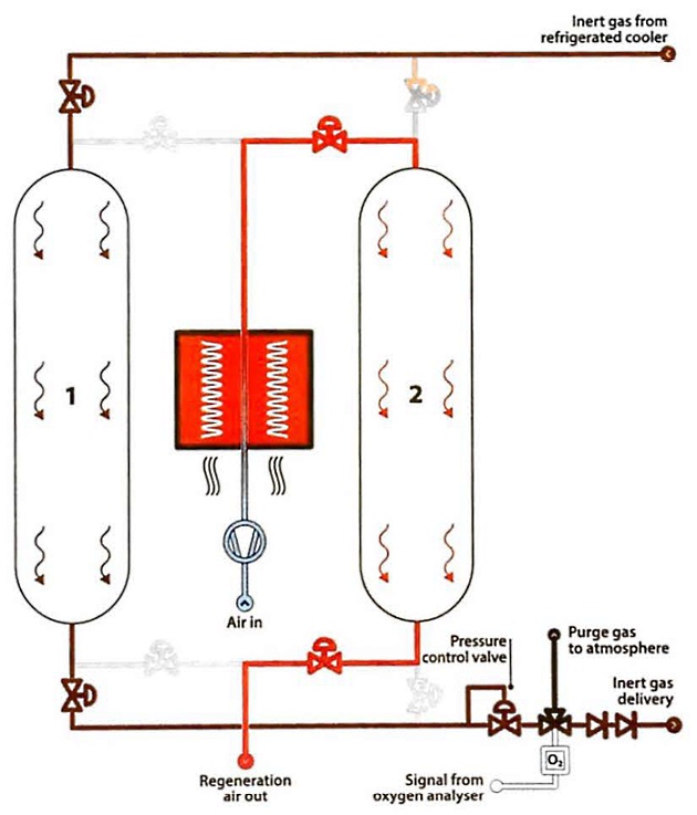
Figure 15 shows that an inert gas generator has three main parts:
- A combustion chamber with scrubbing and cooling (the generator);
- a refrigerated drier;
- an adsorption drier.
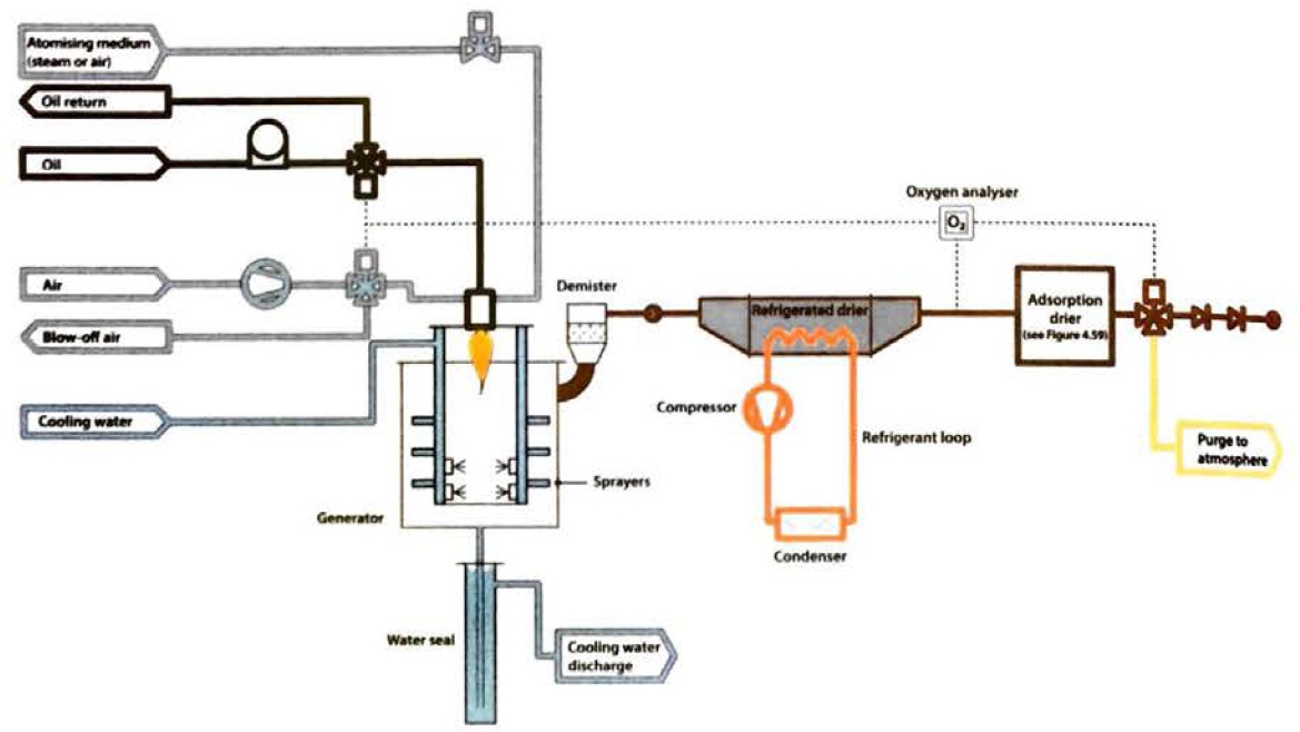
Combustion chamber
The IGC Code requires that combustion type generators be located outside the cargo area and are therefore usually installed in the ship’s engine room. It is common to find the inert gas main permanently piped into the cargo hold/barrier space and temporary connections are provided between the inert gas main and the cargo system for tank inerting operations. When not in use these will be disconnected and blanks fitted. Two non-return valves (or equivalent) are fitted in the inert gas main to prevent any backflow of cargo vapours. When not being used for high capacity tank inerting operations, the inert gas plant is used as required to top up hold/barrier spaces on LPG carriers.
Within the combustion chamber the burner is designed to ensure good combustion, producing a minimum of oxygen residue in the inert gas. Operationally, however, there is a fine balance to be achieved in generator adjustment as minimising oxygen output tends to increase the production of carbon monoxide and further adjustment can result in the overproduction of soot.
The combustion chamber itself is water jacketed. After combustion the inert gas enters the washing section of the generator at a very high temperature and is cooled and scrubbed by spraying with seawater. This also removes soluble acid gases, such as sulphur dioxide and the oxides of nitrogen. The inert gas is then filtered to remove solid particles. The gas leaves the generator at approximately 5 °C above the seawater temperature and, by this time, it will usually be free from sulphur oxides that are formed by burning the sulphur present in the fuel. However, it will be saturated with water vapour so it is further cooled and dried and delivered to the cargo tanks.
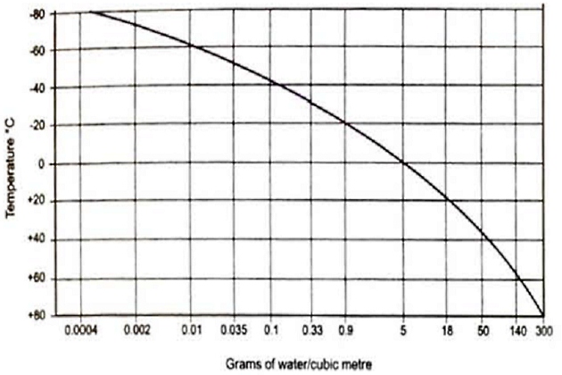
The refrigerated drier
In the refrigerated drier the inert gas is cooled to approximately 5 °C, resulting in the condensation of much of the water vapour. If the drier is adjusted to give a lower temperature in an attempt to reduce the dew point further, there is a risk that the condensed water will freeze and create blockages in the system. Figure 16 shows the content of water vapour in saturated inert gas as a function of temperature, and it can be seen that water content reduces as the temperature is reduced.
The adsorption drier
The adsorption drier consists of two vessels filled with either activated alumina or silica gel. One vessel is on drying duty while the other is being regenerated. Typically, the regeneration/active cycle time is six hours.
Air and Inert Gas DryersDrying in the adsorption drier reduces the dew point of the inert gas to minus 40 °C (-40 °C). To ensure stable combustion in the generator, the pressure in the drying system will be kept constant and this is achieved by means of a pressure control valve, as shown in Figure 17.
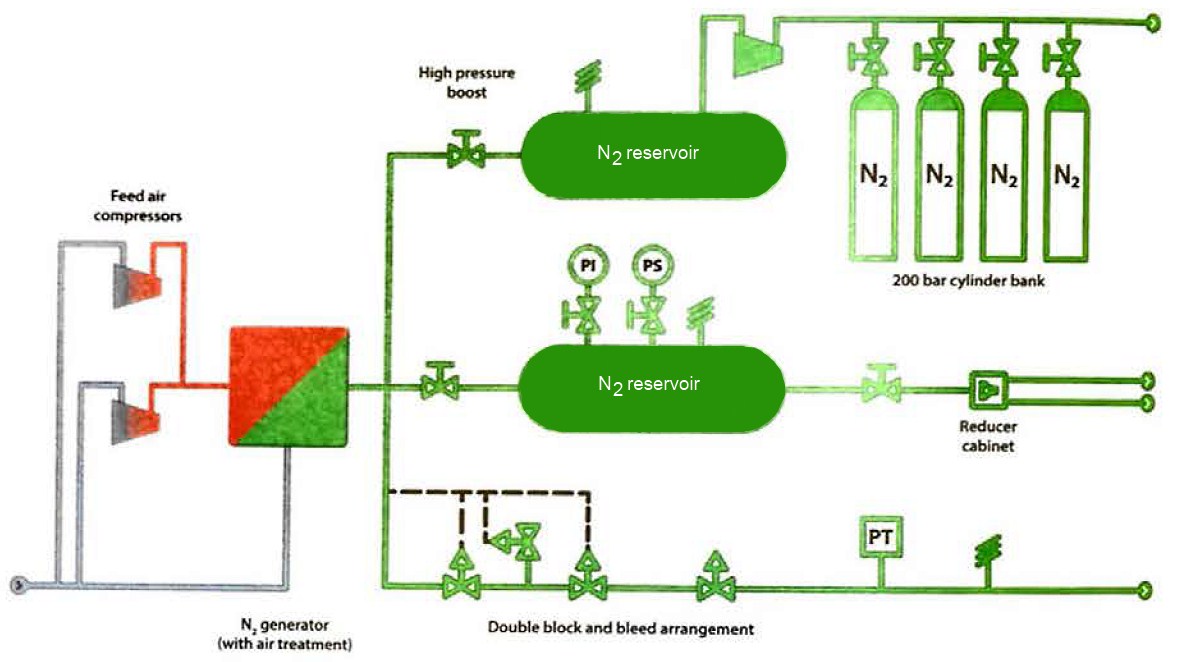
Nitrogen production on ships
There are two common systems for the production of nitrogen onboard ships; one is membrane separation technology and the other is pressure swing adsorption (PSA).
Membrane separation
The membrane separation technology works by passing compressed air over hollow fibre membranes. The membranes divide the a ir into two streams, one of which is essentially nitrogen plus some trace gases and the other a “waste” stream comprised of oxygen, water vapour, and carbon dioxide. This system can produce nitrogen of about 95 to 97 % purity. The capacity of these systems depends on the number of membrane modules fitted and on inlet a ir pressure, temperature and the required nitrogen purity (see Figure 18).
Pressure swing adsorption (PSA)
An alternative method of nitrogen production is called the pressure swing adsorption process. PSA processes rely on the fact that under high pressure, gases tend to be attracted to solid surfaces, or “adsorbed“. The higher the pressure, the more gas is absorbed. When the pressure is reduced, the gas is released, or desorbed.
Air is passed under pressure through a vessel containing a carbon molecular adsorber bed that attracts nitrogen more strongly than it does oxygen. Part or all of the nitrogen will stay in the bed and the gas coming out of the vessel will be enriched in oxygen. When the bed reaches the end of its capacity to adsorb nitrogen it can be regenerated by reducing the pressure, thereby releasing the adsorbed nitrogen. It is then ready for another cycle of producing oxygen enriched air.
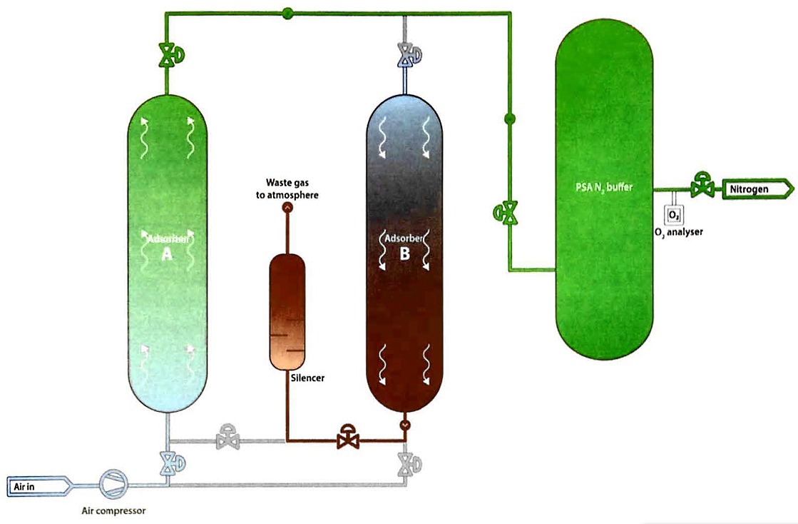
Alternating between two adsorbent vessels allows near continuous production of the target gas. Using pressure equalisation, where the gas leaving the vessel being depressurised is used to partially pressurise the second vessel, increases the overall system efficiency.
Pure nitrogen from the shore
The quality of inert gas produced by shipboard inert gas generators is usually inadequate for oxygen-critical cargoes. Bearing in mind the components in the inert gas, this may create restrictions on use if tanks have been previously gas-freed for inspection, which is often necessary when a change of grade is involved. It is common for cargo tanks to be inerted with nitrogen from shore if it cannot be produced on board. If the terminal is unable to supply nitrogen in vapour form, it may be necessary to arrange liquid nitrogen to be delivered and vaporised on shore.
Electrical Equipment
As stated in article “Liquefied Gas Carrier TypesHazardous Zones“, areas where cargo vapour is likely to occur, in concentrations that are within the flammable range of the cargoes carried, are considered as hazardous areas and, as such, equipment installed or used in such areas should be suitable for use in hazardous locations.
The subject of electrical equipment protection in marine and oil and gas industries is a large one. Many regulatory and certification authorities use their own standards, such as National Electrical Code (NEC) and American Petroleum Institute (API) standards in the United States and a few other countries, but the International Electrotechnical Commission (IEC) standards are widely in use and referenced in the IGC Code and so may be considered to provide a good reference point.
Hazardous area classification
Where flammable gas hazards are being considered, IEC 60079-10-1 (Reference 2.10) provides classifications for areas under consideration as listed in article “Liquefied Gas Carrier TypesHazardous Zones“. All areas in the facility that are not Zone 0, Zone 1 or Zone 2 are considered to be non-hazardous, and general purpose enclosures are usually acceptable in these areas.
Electrical installations on gas carriers
As referenced in the IGC Code, IEC 60092-502 (Reference 2.11) provides guidance on electrical installations in tankers, including gas carriers carrying flammable liquefied gases.
Types of electrical protection
There are many forms and levels of electrical protection, depending on the circumstances of their use. Table details the most common types.
| Classification of explosion proof equipment | ||||||
|---|---|---|---|---|---|---|
| Type of protection general requirements | Marking | Shematic diagram symbol | Basik principle | Standard | Examples | Location |
| General requirements |  | General requirements for the type and testing of electrical equipment intended for the Ex area | EN 60079-0 IEC 60079-0 | |||
| Increased safety | e |  | Applies only to equipment, or its component parts, that normally does not create sparks or arcs, does not attain hazardous temperatures, and the main voltage of which does not exceed 1 kV | EN 60079-7 IEC 60079-7 | Terminals, terminal boxes | Zone 1 or Zone 2 |
| Flameproof enclosure | d |  | If on explosion occurs inside the enclosure, the housing will withstand the pressure and the explosion will not be ptopagated outside the enclosure | EN 60079-1 IEC 60079-1 | Switchgear, transformers | Zone 1 |
| Pressurised enclosure | p |  | The ignition source is surrounded by a pressurised protective gas (min. 0,5 mbar) – the surrounding atmocphere cannot enter the enclosure | EN 6079-2 IEC 60079-2 | Control cabinets, switchgear canibets | Zone 1 or Zone 2 |
| Intrinsic safety | i |  | By limiting the energy in the circuit, the formation of impermissibly high temperatures, sparks, or arcs is revented | EN 60079-1 IEC 60079-1 | Actuators, sensors, instruments, and control circuitry | Zone 0 or Zone 1 or Zone 2 |
| Oil immersion | o |  | Equipment or equipment parts are immersed in oil and therefore separated from the Ex atmosphere | EN 60079-6 IEC 60079-6 | Transformers switching devices | Zone 1 or Zone 2 |
| Quartz filling (sand filling) | q |  | Ignition source is buried in granular packing material (eg sand). The Ex atmosphere surrounding the housing cannot be ignited by an arc | EN 60079-5 IEC 60079-5 | Strip heaters, capacitors | Zone 1 or Zone 2 |
| Encapsulation | m |  | By encapsulation of the ignition source in a moulding, it cannot ignite the Ex atmosphere | EN 60079-18 IEC 60079-18 | Sensors, switching devices | Zone 0 or Zone 2 |
| Type-n protection (non-sparking) | n |  | Slinghtly simplited application of the other protection types – “n” stands for “non-ignition“ | EN 60079-15/2/18/11 IEC 60079-15/2/18/11 | PLCs | Zone 2 |
| Optical radiation | op |  | Suitable measures prevent a hazardous atmosphere from being ignited by optical radiation. | EN 60079-28 IEC 60079-28 | Fibre optic conductors | Optical fibre systems |
Maintaining electrical protection
As with so many other protective systems, proper maintenance is vital in ensuring protection levels remain as intended. Poor maintenance practices very easily, and seriously, degrade the designed levels of protection. Maintenance on electrical protective equipment must only be carried out by competent staff and generally only genuine spare parts should be used. Sea ls and covers should usually be replaced as per the manufacturer’s instructions, with no bolts or fixing missing. See article “Comprehensive Guide to Risk Assessment and Process Safety ManagementInspection and Maintenance” for further discussion of inspection and maintenance of equipment and systems.
Cargo Instrumentation
Liquid level instrumentation
The IGC Code and Classification Society rules require that every cargo tank is fitted with at least one liquid level gauge.
Specific types of gauging system are required for certain cargoes, as defined in the IGC Code.
The IMO classification for gauging systems is as follows:
- Indirect systems – these may be either weighing methods or flow meters;
- closed devices that do not penetrate the cargo tank, where ultrasonic devices or radio isotope sources may be used;
- closed devices that penetrate the cargo tank, such as float gauges and bubble tube indicators;
- restricted devices that penetrate the tank but which release small volumes of liquid or vapour to atmosphere when in use, such as fixed or slip-tube gauges. When not in use, the restricted device will usually be kept completely closed.
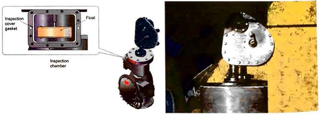
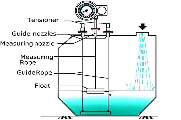
Float gauges
The float gauge is widely used on all gas carriers. It consists of a float attached by a tape to an indicating device that can be arranged for local and remote readout. Figure 23 shows a typical float gauge installed in a tubular well. Float gauges have valves for isolation so that the float can be replaced in a safe atmosphere. The most common isolation valve used is a gate valve and caution needs to be taken to ensure that the valve gate is not closed on the float tape, which could result in the tape being cut and the float lost within the tank.
The float should, ordinarily, be lifted from the liquid level when not in use. If left down, liquid sloshing while at sea will damage the tape tensioning device. Float gauges cannot normally register a liquid level of less than 10 cm from the tank bottom.
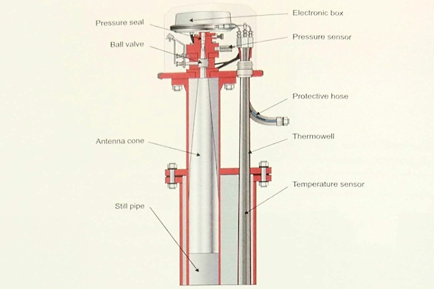
Radar gauges
Tank level gauges working on the some principle as radars are now used on many LNG and LPG carriers. Unfortunately, the frequency they use is absorbed by the chemical bonds in “unsaturated” hydrocarbons (see article “Properties of liquefied gasesSaturated and unsaturated hydrocarbons“), so these instruments may not be suitable for all cargoes.

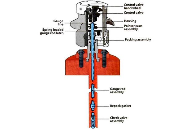
Slip-tubes
While not o common gauging system, slip-tubes are used in some cases on Type C tanks (ie deck tanks). Slip-tubes have the unique characteristic of allowing a small amount of cargo vapour or liquid to be released to atmosphere during level measurement.
Slip-tubes are, therefore, defined in the IGC Code as a restricted type of gauging device and it prohibits their use with toxic cargoes.
Some terminals will not permit the use of slip-tubes, depending on cargo type, because of the small quantity of gas that is released.
Slip-tubes have an orifice, at their upper end, through which liquid or vapour can be released. The IGC Code limits the size of this orifice to 1,5 mm in diameter unless an excess flow valve is fitted.
The lower end of the slip-tube is open to the cargo tank environment. The device slides up and down through a gland fitted in the tank dome. The observed differences between either liquid or vapour venting from the orifice provide an indication of when the liquid level has been reached and, by reading from the markings on the tube itself, the actual liquid level can be read. Because of the considerable depth of many tanks it is usual to find that a number of slip-tubes are fitted, with each individual unit covering a certain range of tank level measurements, typically 1,5 to 2,0 metres.
Slip-tubes are a simple and direct method of measurement but, because of a certain amount of high pressure spray released to the atmosphere, special precautions may need to be taken, such as the wearing of protective clothing. Operational procedures should be in place for their use and these will usually detail, amongst other things, how to direct the released spray from the slip-tube away from personnel. The use of slip-tubes is generally limited to emergency backup of the dosed gauging devices and to Type C tanks only.
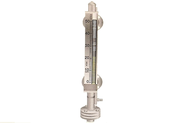
Magnetic level transmitters
The magnetic level transmitter can be fitted as either direct in-tank installation or as external tank mounting to a magnetic level gauge.

The transmitter detects the position of the magnetic float within the level gauge chamber and provides continuous level measurement that is highly accurate.
Level alarm and automatic shutdown systems
With the exception of Type C tanks having a capacity of less than 200 m3, every cargo tank is required by the IGC Code to be fitted with an independent high level sensor giving audible and visual alarms. Float, capacitance, magnetic (ie Reed switch), or ultrasonic sensors may be used for this purpose. An independent sensor other than the high level alarm is required to automatically stop the flow of cargo to the tank by actuating a shutoff valve.
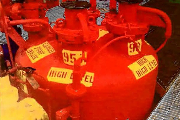
A typical sequence might be:
- 95 % = alarm;
- 97 % = alarm;
- 98,5 % = close filling valve;
- 99 % = ESD1.
During cargo loading there is a danger of generating a significant surge pressure if the valve stopping the flow closes too quickly against a high loading rate. (For further information on surge pressure see article “Equipment and cargo system of LNG onshore terminalsPipelines and valves – engineering standards and surge pressure“).
Pressure and temperature monitoring
The IGC Code requires pressure monitoring throughout the cargo system. Appropriate positions include cargo tanks, pump and compressor discharge lines, liquid crossovers and vapour crossovers. In addition, pressure switches are fitted to various systems to protect personnel and equipment by operating alarms and shutdown systems.
The IGC Code also requires at least two devices for indicating cargo tank temperatures. One is placed at the bottom of the tank and the second near the tank top, but below the highest allowable liquid level.
Where cargo is carried in tanks requiring a secondary barrier at a temperature of below minus 55 °C (-55 °C), the IGC Code requires temperature indicating devices within the insulation or on the hull structure adjacent to the containment system. The thermocouples will usually be set to provide adequate warning before the lowest temperature for the hull steel is approached.
Pipeline temperature measurement
Temperature measurement is also used in pipeline systems to assist operators in monitoring the cargo transfer process, specifically during cool-down and warm up operations. Sensing elements may be either internal or external. An example of an internal type element is a thermowell, which is a closed pocket screwed into a boss on the pipeline into which a temperature sensing element is inserted. The thermowell protects the temperature probe from direct contact with the pipeline contents and allows for maintenance on the element without having to gas-free the pipeline. Note that there have been reports of thermowell failures in service. In some cases, where the thermowell is of considerable length and installed in a liquid line, it can be subject to cyclical loading due to the flow across the thermowell. This cyclical loading induces a resonance that may subsequently result in fatigue failure of the thermowell near the threaded boss. These failures may be discovered when the broken section is found in the manifold strainers at the discharge port, in a cargo tank at inspection or, in some cases, as a result of a leak of cryogenic liquid.
Read also: Overview of the Carriage of Liquefied Gases by Sea
The pipeline temperature measurement does not have a role in the custody transfer process and, therefore, does not generally require a high degree of measurement accuracy. Care should be taken when designing pipeline systems to ensure that proper consideration is given to, for example, the intended service, in terms of number, location and type of temperature sensing elements. External sensing elements, suitably installed and insulated, are a common alternative to probes inserted in the pipeline (“Thermowefls in LNG Carrier Liquid Lines”, Reference 2.21).
Gas detection system
Releases of flammable or toxic gases pose an immediate threat to both personnel and equipment. It is necessary to detect accidental discharges as early as possible to avoid the possibility of confined or partially confined vapour cloud explosions, flash fires and the presence of asphyxiating chemical gases. Provision for greater levels of leak or release detection on board ships and at facilities is considered prudent. This is increasingly important when operating at minimum manning levels.
The provision of gas detection systems onboard gas carriers is important and the IGC Code requires gas carriers to have a fixed gas detection system with audible and visible alarms. The IGC Code requires detector heads to be installed in the following spaces:
- All enclosed cargo and cargo machinery spaces (including turret compartments) containing gas piping, gas equipment or gas consumers;
- other enclosed or semi-enclosed spaces where cargo vapours may accumulate, including interbarrier spaces and hold spaces for independent tanks other than Type C tanks;
- airlocks;
- spaces in gas-fired internal combustion engines (crankcases, sumps, scavenge spaces, cooling system vents);
- burner ventilation hoods and gas ducts for fuel gas systems;
- cargo cooling/heating circuits, including overboard water discharges;
- inert gas generator supply headers;
- motor rooms for cargo handling machinery.
They may also be fitted in accommodation space entrances and accommodation and engine room ventilation intakes.
The detector heads are commonly sited with regard to the density of cargo vapours. This means that for heavier than air vapour the detector heads will be sited at a low level, and for lighter than air vapours at a high level (see Table “Properties of liquefied gasesPhysical properties of gases“). The sensing unit for the gas detection system is normally located in the cargo control room or the navigational bridge. Provision should be made for regular testing of the equipment. Span gas, of a certified mixture for calibration purposes, will be readily available and possibly permanently piped.
Permanently installed gas detection systems used to activate safety shutdown functions will usually be of the continuous detection type, capable of immediate response. An example is the gas detection for double-walled fuel gas piping and the spaces containing gas consumers. Otherwise, sampling type installations may be acceptable.
In addition to the fixed gas detection system, the IGC Code requires that every ship must have at least two sets of certified safe (see point “Electrical Equipment” above) portable gas detection equipment adapted to the cargoes listed in the Certificate of Fitness. Means for measuring oxygen levels in inert atmospheres are also required by the IGC Code.
The two principal types of gas detectors are catalytic and infrared (IR).
The catalytic gas detector consists of an electrically heated platinum wire coil covered with a ceramic base catalyst. This sensing element responds to a flow of gas into the detector housing by heating up and altering the resistance of the platinum coil. The degree of heating is proportional to the a mount of combustible gas present and can be displayed on a meter.
IR type systems are increasingly used and:
- Are more resistant to contamination than existing alternatives;
- can operate in inert atmospheres.
The IR detector is a sealed detection tube containing both transmitter and receiver. The output (ie gas present) is proportional to the amount of IR radiation absorbed by the gas. However, IR devices suffer from the some limitations as the radio-frequency level devices described above, ie the molecular composition of “unsaturated” hydrocarbons causes incorrect readings. For this reason, IR gas detectors are not suitable to measure concentrations of ethylene, propylene, butylene, butodiene and vinyl chloride gases – especially in high concentrations.
It is prudent to ensure that personnel are familiar with gas detection equipment and its operating principles. Manufacturer’s instructions should always be followed. To show the correct readings, the instrument will likely need to be calibrated with the correct gas for the cargo being carried. Using a meter calibrated with the incorrect span gas will not give accurate readings (ie when the same meter is used for more than one purpose, such as on deck and for bunker tank entry). When a low percent volume is detected, some meters will automatically display the lower explosive limit (LEL).
While this is correct in the presence of oxygen, in many instances the atmosphere being measured may have little or no oxygen. Some conversion may be required to establish the %LEL reading from the percentage volume (%vol).
LNG custody transfer measurement systems (CTMS)
For LNG carriers to meet the requirements for custody transfer, the cargo tanks are commonly calibrated by an independent measurer, and high accuracy level, temperature and vapour pressure measuring equipment is installed. This is often supported by data logging and cargo calculation facilities referred to as custody transfer measurement systems (CTMS) (see article “Measurement and calculation of cargo on gas carriersLNG Quantification“). Such systems are usually approved by local customs authorities.
The need for this equipment has developed from the LNG trade practice of relying on shipboard measurement of cargo to determine the quantity of product transferred between seller and buyer.
Accuracy is important in these circumstances since the quantities determined are also used as the basis for import duties and fiscal accounting. The GIIGNL publication, “LNG Custody Transfer Handbook” (Reference 2.22), contains further details on LNG custody transfer.
Such a system normally includes:
- Level gauges;
- temperature sensors;
- trim and list indicator;
- pressure gouges or sensors.
Some LNG ships are fitted with a means of determining cargo density. However, its value is more usually derived from the analysis of samples carried out in the terminal.
Integrated system
Some gas carriers relay readouts from cargo instrumentation to an online computing system. This allows the ship immediate access to cargo quantities and cargo tank conditions at any stage of loading or discharging. To permit this system to function a shipboard method of density determination is required. This should not be confused with density values, which may be noted on the Bill of Lading (B/L) used for custody transfer.
Calibration
Instrumentation is only accurate if properly calibrated. Calibration can be carried out onboard by the crew, using calibration instruments, or it can be carried out by service engineers carrying their own calibration instruments. Calibration instruments should be calibrated at regular intervals, in specialised facilities, and carry a calibration certificate.
Custody transfer systems are also subject to periodic calibration and certification, which is typically accomplished by a third party external auditor.
The ISM Code, in Chapter 9 of SOLAS (Reference 1.6), recommends that each ship carries a calibration procedure and that confirmation of compliance with that procedure is available onboard.
Ship/Shore Links
The functions of the cargo ESD system are to stop cargo liquid and vapour flow in the event of an emergency, and to bring the cargo handling systems to a safe, static condition. While the IGC Code specifies requirements for shipboard ESD systems, it does not consider the activation and operation of ESD systems at shore installations. Commonly, linked systems are installed such that activation of an ESD trip on the ship will send an ESD signal to shore, and vice versa.
At the highest level, the purpose of the ship/shore link (SSL) is to transmit, without delay, a signal from one party to the other, ie ship to shore or vice versa. A number of different link technologies are currently used in the liquefied gas industry:
- Electric;
- fibre optic;
- pneumatic.
The electric and fibre optic systems also have the capacity to transfer additional information, such as “emergency” telephone links and data from mooring tension monitoring systems, etc.
Further discussion of linked ESD systems can be found in article “Ship/shore interface for safe loading and unloading of LNG/LPGLinked Emergency Shutdown (ESD) Systems“. An extensive description of the SSL can be found in SIGTTO’s, “ESD Arrangements & Linked Ship/Shore Systems for Liquefied Gas Carriers” (Reference 2.16).