Dive deep into the operation and maintenance of spray pumps on LNG carriers with our comprehensive guide. From understanding their purpose and principles to mastering operational procedures and maintenance protocols, ensure smooth functioning and safety at sea. Explore alarm settings, starting systems, and motor maintenance for a thorough understanding of these crucial components.
Reference: SIGTTO “LNG Shipping Suggested Competency Standards”, Sections:
1 Have an awareness of their purpose and operating principles:
- location and typical number.
2 Know and understand their principles, operating parameters and limitations:
- design features.
3 Know and understand operational requirements and procedures:
- the operational requirements with respect to limitations on number of starts and required liquid level;
- correct starting sequence;
- pump control;
- setting up;
- starting;
- the use of automatic control sequencers;
- shutdown.
4 Know and understand their alarm settings and resulting actions.
5 Know and understand the starting system:
- maintenance;
- testing;
- emergency starting arrangements.
6 Know and understand the pump motors and cabling:
- maintenance;
- testing.
The spray pumps are used to:
- cool down the liquid header prior to discharging;
- prior to arrival at the loading terminal, cool the cargo tank during a ballast voyage by discharging LNG to the spray nozzles in the tanks;
- pump LNG from the tanks to the forcing vaporiser when forced vaporisation of LNG is required;
- enable the tanks to be stripped as dry as possible for reasons such as a cargo tank entry, for the commercial considerations of “heeling out” at the discharge port or in preparation for refit.
To distribute the incoming liquid, the spray line arrangement on each Liquefied Natural Gas and Liquefied Petroleum Gas Cargo Containment Systemcargo tank connects to spray rails within the tank. This promotes cargo evaporation and improves the rate of cooldown.
On the ballast voyage, the ship will usually retain sufficient liquid (known as “heel”) to ensure that some is available for cool down of al I tanks prior to the arrival at the loading port.
Commercial considerations may dictate that the ship fully heels out (discharging as much as possible while still allowing the gauging system to function). This decision is made either on the basis of the costs of the retained LNG versus the cost of bunker fuel, because of the voyage charter terms or because of the propulsion plant fitted.
| Symbol | Tank type | Description |
|---|---|---|
 | Membrane type | On LNG ships with membrane tanks, the temperature at the top of the tank will remain around minus 65 °C (-65 °C) without further circulation for as long as there is liquid at the bottom of the tank, assuming only moderate heel ageing. |
| Note: The spray pump does not touch the deck. Everything is suspended from the top. | ||
 | Type B | On LNG ships with the Type B tanks, such as the Moss system design, it is necessary to keep a slightly larger amount of liquid on board to ensure that there is sufficient for the spray pumps to circulate cargo through the spray rail in the tank dome at the end of the voyage . |
| Moss type | Because of the tank construction on a Moss system design, it is necessary to circulate liquid from the spray pump at the bottom of the tank through the spray rail at the dome to maintain an even temperature all round the tank and meet the designed temperature parameters at the equatorial region. Therefore, a stripping/spray pump is installed in each tank for cooling purposes and for forced vaporisation of LNG. It is typically rated at 50 m3/h at 135 m head of LNG. |
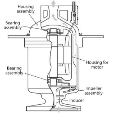
All pumps should be identical and from the same manufacturer. The spray pumps should be installed as low as possible in the tank so that they can maintain enough heel to prime the pump and be used for stripping.
| Spray/stripping pumps/typical details | |
|---|---|
| Capacity | 50 m3/h × 135 mLc |
| No. per tank | 1 |
| Not all Moss ships have spray pumps in all tanks. |
| Moss ships may operate by gathering all remaining liquid into a single tank (or by leaving a cargo heel in one tank while discharging the others). This allows the tank to be designated as the supply cargo tank for supplying the spray pump for cooling purposes on the ballast voyage. This is achieved by spraying the other tanks in rotation. | |
The capacity and head of each spray pump is determined by the containment design and must meet the highest of the following requirements.
- spray cooling all the cargo tanks;
- pre-cooling of the liquid lines;
- stripping main cargo pump unpumpables within 2 hours.
Generally, the spray pump design is similar to the Use of Cargo Pumps on Liquefied Gas Carrierscargo pumps.
The principle for operation is similar to that of the main cargo pumps and so a similar operating procedure is used:
- check the level of the liquid in the tank is above the minimum recommended by the manufacturer;
- the pumps must not be started when the tank is dry;
- the pump must be completely submerged in LNG to ensure that the top bearing is cooled.
If the intention is to strip the tanks using the spray pumps, these must be started before stopping the main cargo pumps. This will prevent the situation where the main cargo pump reduces the liquid level to below the minimum required to start the spray pumps.
General Description
| A Typical Specification | |
|---|---|
| Number of stages | 2 |
| Operating temperature | minus 161,5 °C (-161,5 °C) |
| Capacity rated flow | 50 m3/h |
| Rated head | 135 m |
| Power rated | 16,9 kW (Motor rated at 22,4 kW) |
| Efficiency | 54,4 % |
| Rotational speed | 3 560 rpm |
| Minimum starting level | 0,25 m |
Operation
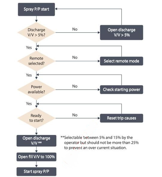
The spray pumps are started and stopped from the cargo control room (CCR), by the IAS schematic display and the associated group displays. The pumps will be automatically stopped in the event of certain shutdown trips being activated.
The pumps should be started individually as required, with the pump discharge valve open (approximately 5 % to 15 % depending on the ship’s arrangements). If the pump discharge valve position does not open to a minimum of 5 %, the pump will not start.
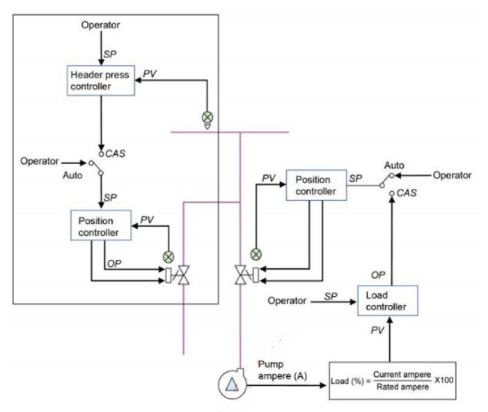
Strip/spray pump load control
It is possible to control the flow rate of the centrifugal type pump by adjustment of the discharge valve, opening it to increase the flow rate. This increases the pump load so that the motor current will be increased. The IAS can maintain or change the pump load by adjustment of the discharge valve according to pump load requirements, so a cascade type control loop is established between the discharge valve controller and the pump load controller.
Ammeters in the starter panel display the load current. In practice, the operator will follow the process sequence and indications on the IAS. The monitors calculate the pump load as a percentage, comparing the value to the maximum rated current.
On initial starting, the load for each pump is controlled at about 60-65 % and can then be adjusted to approximately 80-85 %
Strip/spray line header pressure control
When involved in cargo tank cooldown operations, or when supplementing the fuel gas supply using the Use of Vaporisers on Liquefied Natural Gas Carriersforcing vaporiser, the strip/spray line header pressure should be maintained at a constant level and a control valve installed on the return line is provided for this purpose.
Setting and starting up
Restart of pumps in normal operation is restricted by the liquid level above the submerged electric motor. Pumps must not be restarted with tank liquid level below 0,3 m.
For a liquid level below the motor centreline, restart after 30 minutes and carry out no more than 2 restarts within one hour.
Alarms and resulting actions
Typically,the stripping/spray pumps will be stopped automatically should any of the following occur:
- vapour header pressure below or equal to atmospheric pressure plus 30 mb (ESDS: Stage 1 – see Section 3.5);
- extremely high level in the cargo tank;
- activation of ship/shore pneumatic, fibre-optic or electrical shutdown (ESDS Stage 1 – see Section 3.5);
- low motor current;
- high motor current (electrical overload);
- low discharge pressure with time delay at starting;
- the end of an IAS cargo automatic sequence;
- pump alarms activated;
- motor single-phasing;
- cargo tank level low-low.
The spray pumps are more commonly soft start but can be direct on-line if required, i. e. if the soft start fails. Non-return valves are installed inside the tanks after the spray pump discharge flange. These valves, along with the soft starting arrangements, assist in the reduction of any excessive liquid hammer that can occur if the pumps are not started in accordance with the steps outlined.
| Normal Start-up | |
|---|---|
| 1st restart | minimum 5 minutes after shut down |
| 2nd restart | 15 minutes after 1st restart |
| 3rd restart | 30 minutes after 2nd restart |
| No more than 4 starts/restarts within one hour | |
Soft start: electronic starting sequence, gentle start and gentler on ship’s power plant.
Direct on-line: direct starting (i. e. press button and pump goes to full starting current immediately).
The power supply to the spray pump motors comes via cargo switchboards, which are normally arranged in two independent sections, either operated as coupled, via a bus-tie connection, or independently.
Each of the cargo switchboards can be supplied by either or both of the main switchboards.
Read also: Cargo System – Tank Construction
Because of the high electrical load imposed on the cargo switchboards by running the main cargo pumps, the number of spray pumps that could be run in this situation is limited by the electrical power management system (start block).
The pumps should be started individually and sequentially, with the pump discharge valve open (approximately 5 % to 15 %, depending on the ship’s arrangements).
If the pump discharge valve position does not open to a minimum of 5 %, the pump will not start due to a starting interlock.
| Spray pump control system | |
|---|---|
| Local Control | Operation of the equipment (start and stop) is performed at the cargo switchboard using the local control panel. |
| Remote Control | Operation of the equipment (start and stop) is performed from the IAS. Equipment cannot be operated in both local and remote modes at the same time. |
| Manual Control | Operation of the equipment is performed manually by the operator from the IAS operator stations (remote mode only). |
| Automatic Control | Operation of the equipment is performed by the IAS control function (remote mode only). |
The spray pumps, pipeline system and starters must be designed to minimise liquid hammer during starting, so the spray pump non-return valves should be installed in the cargo tank immediately above the pump and frequency controlled or soft starters should be incorporated into the system.
LNG is electrically non-conductive. Therefore, the spray pump relies on the flow of liquid through the pump for motor cooling and bearing lubrication. Its location rules out normal in-service maintenance, so reliability is an important factor.
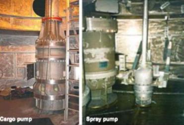
The normal practice is for spray pumps to be removed “complete” from the cargo tank during refit and then fully overhauled by either the manufacturers or an approved specialist company.
While in-service, the operator must closely monitor spray pump performance and watch for any apparent decline. For example, debris in the spray line filters will indicate a problem within the cargo tank. Performance monitoring, by comparison with historical records if necessary, is an important aspect of the associated maintenance. It is good practice to alternate the use of spray pumps to optimise their running hours.
It is good practice to maintain a log of the insulation readings to earth and between phases, for cargo pump motor windings and associated supply cables, as these may be required for inspection purposes. The readings should be taken before every discharge port, while following established high voltage safety precautions.
I feel that pumps operating on an FLNG are a more severe environment than conventional LNG Tankers. This because LNG entrained with construction stainless steel filings can settleout in the LNG huge storage tanks on land based LNG Plants. When loaded on the LNG tanker the LNG is virtually free of this contamination. This is why bearing damage to Spray Pumps on LNG Tankers has not been a problem.
However on FLNG, the storage tanks are much smaller. This and constant FLNG movement due to ocean waves, now exposes the spray pumps to the above foreign material from construction and constant well supply.
Flowing this contaminated LNG thru the
FLNG exposes the pump steel ball bearings to damage and reduced availabllity.
Experience has shown that deploying ceramic bearings on LNG pumps has eliminated wear concerns due its increased hardness.
For all pumps on FLNG, the Industry should dictate ceramic vs. steel ball bearings.
I have recently witnessed Factory Acceptance Testing on some LNG Spray Pumps that deployed steel ball bearings.