Technical tankers information LNG and LPG is extensive. Tankers are large vessels used to transport liquids or gases in bulk. They come in different sizes and types, such as oil tankers, chemical tankers and liquefied gas carriers. Tankers are designed with special features to safely transport certain types of cargo. Safety rules and protocols are strictly followed to prevent accidents and protect the environment during tanker operation.
These tankers are equipped with modern insulation systems, protective structures and safety measures to operate in the low temperature and high pressure environments of these liquid gases. They are equipped with specialized loading and unloading systems and comply with strict international regulations to ensure safe and efficient transportation of LNG and LPG.
Introduction
Brief History
In 1910, a Pittsburgh motor car owner walked into chemist Dr. Walter Snelling’s office, complaining that the gallon of gasoline he had purchased was half a gallon by the time he got home. He thought the government should look into why consumers were being cheated because the gasoline was evaporating at a rapid and expensive rate. Dr. Walter Snelling, under the direction of the US Bureau of Mines investigated gasoline to see why it evaporated so fast and discovered that the evaporating gases were propane, butane, and other hydrocarbons.
In 1911, Dr. Snelling isolated and identified the two major components of LP-gas–propane and butane, and soon developed a practical method of removing them from natural gasoline.
Dr. Snelling built a still that could separate the gasoline into its liquid and gaseous components and sold his propane patent to Frank Phillips, the founder of Phillips Petroleum Company.
By 1912, propane gas was cooking food in the home. The first car powered by propane ran in 1913. By 1915 propane was being used in torches to cut through metal. LPG has been used as a transportation fuel around the world for more than 60 years.
Gas shipping began in the late 1920s and the earliest ships carried butane and propane in pressure vessel at ambient temperature. The subsequent development of refrigeration techniques and, more particularly, metals suitable for low temperatures permitted the carriage of cargoes at temperatures below ambient. In the late – 1950s these gases began to be partially refrigerated commercially and ships were built with pressure vessel of low temperature material to carry the cargo. By the mid-1960s fully refrigerated LPG ship’s were in service carrying cargo at atmospheric pressure; ethylene and LNG ships had also entered service. In the meantime ammonia had become a common cargo, and chemical gases such as butadiene had become commercially important.
The first ship Methane Princess was taken into operation in 1964 and remained in operation until it was scrapped in 1998. Until the end of 2005 a total of 203 vessels have been built, of which 193 are still in service.
At the moment there is a boom in the fleet, with a total of more than 140 vessels on order at the world’s shipyards. Today the majority of the new ships under construction are in the size of 120 000 m3 to 140 000 m3. But there are orders for ships with capacity up to 260 000 m3. As of 6 March 2010, there are 337 LNG ships engaged in the deep sea movement of LNG.
Liquefied natural gas (LNG), Shore Natural Gas Storage Tanksnatural gas (primarily methane) that has been liquefied for ease of storing and transporting. LNG takes up about 1/600 the space that natural gas does in its gaseous form, and it can be easily shipped overseas. LNG is produced by cooling natural gas below its boiling point, -162 °C (-259 °F), and is stored in double-walled cryogenic containers at or slightly above atmospheric pressure. It can be converted back to its gaseous form by simply raising the temperature.
LNG is more practical than liquefied petroleum gas or other liquid gases, particularly for use in large volumes, because it has the same chemical composition as natural gas. This fact and the growing demand for natural gas have stimulated LNG production. Moreover, LNG technology has made it possible to utilize natural gas from remote areas of the world where it previously had no commercial use and was flared (burned). Special tankers transport LNG from such countries as Algeria, Borneo, and Indonesia to markets in Europe, Japan, and the United States.
Liquefied Gas – It is a liquid form of a substance, which at normal ambient temperature and atmospheric pressure would be a gas.
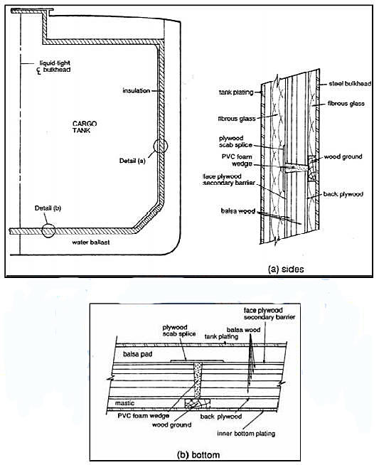
It is carried by special tankers, which is double hull. The cargo tank is secured with balsa wood, glass fibres, PVC and polyurethane, and the tank itself is made of nickel alloy.
Methods by which gas can be liquefied:
- Liquefaction by removal of heat.
- Liquefaction by pressurizing.
5 Groups of Liquefied gas cargoes:
- LNG – (Liquefied Natural Gas) is a natural gas from which most of its impurities is removed such as sulphur and the principal constituent is methane.
- LPG – (Liquefied Petroleum Gas) is produce from refinery or maybe produce in conjunction with crude oil or natural gas mainly propane or butane.
- LEG – (Liquefied Ethylene Gas) is produced by cracking of LPG Ethylene, propylene, & butylenes are example of this cargo.
- NGL – (Natural Gas Liquid) is a natural gas from a well in smaller quantities of heavier hydrocarbons. Ex. Ethane & Pentane.
- CHEMICAL GASES – are group of liquefied gases produced through chemical gases, example of these are chlorine, vinyl chloride monomer (VCM), ammonia. Characterized by presence in the molecular structure of atoms other than carbon and hydrogen. Most of chemical gases are chemically reactive.
Stenching – sulfur compounds such as mercaptans are often added as odouriser prior to sale to aid in detection of these vapours.
Basic Principles of Gas Transport
A gas can be liquefied either by increasing its pressure, reducing its temperature, or both. The combination of pressurizing and cooling are fundamental to gas carrier design, and the scientific aspects of these processes are explained in Appendix 3.
Gas cargoes are carried in a liquefied state, because the liquid occupies up to 850 times level volume, which means that this much extra cargo can be carried, which makes the trade economically feasible. The liquid is at its boiling point, and will vaporize readily.
If the cargo is to be carried pressurized at ambient temperature, the cargo tanks have to be able to withstand the pressure of the cargo at the highest ambient temperature anticipated. If the cargo is to be carried at temperatures below ambient, the cargo tanks have to be able to withstand the pressure of the cargo; the tank material must be ductile at cargo temperature and be compatible with the cargo. The tanks also have to be insulated.
Most of the commercially important gases have a specific gravity about half that of water, which means that the cargo tank can extend much higher above the waterline than is possible for oil tanker. The low specific gravity of the cargo is also the reason that the cargo capacity of a gas carrier is usually quoted in terms of volume (cubic meters) rather than deadweight, resulting in the molded depth becoming relatively large; this fact and the extent of free surfaces in cargo tanks necessitate particular attention to stability. The cargo specific gravity increases as the cargo temperature is reduced.
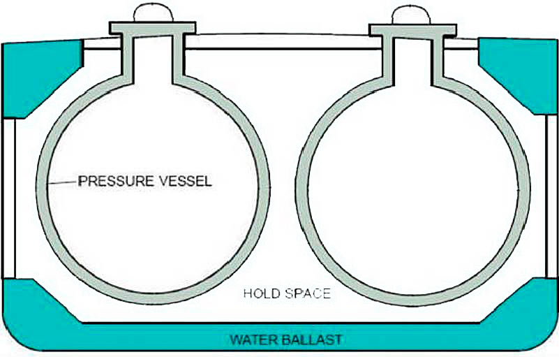
Pressurized Carriage
Cargo tanks have to be able to withstand relevant pressures if the liquefied gas cargoes are to be carried at ambient temperatures. A highest temperature of 45 °C is normally assumed, which corresponds to a pressure of about 17 kg/cm2 for propane, which is the most volatile cargo normally carried at ambient temperature. 17 kg/cm2 is the common design pressure for this type of cargo tank, though a lesser design pressure can be used for ships with restricted cargo requirements.
Cylindrical and spherical pressure vessels have a high degree of proven reliability and this is backed up by considerable experience with pressure vessels in water boilers and oil refineries.
Pressure vessel type tanks are used to contain the cargo because normal integral, membrane or rectangular independent tanks cannot withstand pressure above about 7 kg/cm2. Pressure vessels are made from circular sections generally cylindrical in shape with hemispherical or elliptical heads. It is possible to calculate stress levels in pressure vessel shells quite easily as they have an even contour, with the almost total absence of internal structure and the avoidance of stress concentrations.
Refrigerated Carriage
If the cargo is to be carried refrigerated (i. e. at temperatures below ambient), the tank has to be made from special material. Normal steels have reduced ductility at temperatures. For marine purposes, normal mild steel is suitable for cargo temperature down to 0 °C. Steel with fine grain structures and improved tensile properties can be used at lower temperatures. There are 5 grades of such steel, known as grades A, B, C, D and E. These steels can be used for independent cargo tanks, depending on thickness, with a temperature limit of 0 °C for grades A, B and C, -10 °C for grade D, and 25 °C for grade E.
For temperatures down to -55 °C can alloy steel is necessary for cargo tanks, the most common one being fully-killed fine-grain aluminum-treated carbon manganese steel. For temperatures as low as -104 °C (ethylene) or -163 °C (LNG) metals such as aluminum alloys or special alloys such as nickel steels or stainless (austenitic) steels are necessary for cargo tank construction. The design pressure of the tank depends on the intended degree of refrigeration of the cargo. If the cargo is refrigerated so that its pressure is equal to atmospheric pressure boiling point or if the cargo is refrigerated to below ambient temperature, but is not fully refrigerated, it can still exert a significant vapor pressure and the cargo tanks have to be pressure vessels made from low temperature metal. In this case, the cargo is said to be semi-refrigerated.
If the cargo is below ambient temperature it is necessary T3 insulate the cargo tanks to reduce the effects of heat from the atmosphere warming the cargo up, and to prevent the cargo cooling normal hull steel below their limiting temperatures. It is also necessary to devise some means of dealing with cargo boil-off generated by any heat leakage through the tank insulation.
Cargo-containment systems for Pressurized and Refrigerated carriage
The primary material used in all LNG containment systems is considerably more costly than conventional shipbuilding steels. Independent tanks are generally constructed of aluminum alloy, although 9 % nickel steel and stainless steel are also acceptable materials. Independent tanks are sufficiently robust to independently withstand the hydrostatic and hydrodynamic forces and to transmit these forces to the surrounding hull structure through their foundation support system and to accommodate thermally induced stresses caused by the temperature difference between ambient and LNG cargo service temperatures. Membrane containment systems are generally constructed of either stainless steel or Invar, a high nickel content alloy with minimal thermal expansion characteristics. These materials, while substantially more costly per unit weight than the aluminum alloy of typical independent tanks, can be designed into competitive systems owing to the relative thinness and resulting light weight of the membrane, which cannot independently withstand the forces encountered and relies on a load-bearing insulation system to transmit forces to the hull structure. Typically, independent tanks require far greater quantities of aluminum alloy than membrane systems require of either stainless steel or Invar. The load-bearing thermal insulation for membrane containment systems must be capable of transmitting the hydrostatic and hydrodynamic loads to the hull structure. Load-bearing insulation systems for membrane tanks are generally more complex and more costly than the thermal insulation systems installed with independent tanks.
Independent tank systems, being separate from the hull structure, typically are designed with sufficient space between the containment system (tank plus insulation) and the hull structure to allow human access for inspection, maintenance and repair of the outer surface of the insulation and the inner surface of the vessel’s double hull structure. Membrane containment systems, being in intimate contact with the hull structure, do not permit such access and, therefore, make the inspection of either the insulation system or the inner hull structure far more difficult and expensive to accomplish.
The several designs that have found acceptance incorporate relatively expensive materials suitable for low temperature (cryogenic) applications, and they attempt to achieve economic competitiveness through a balance of quantity of material versus material price, complexity of design and labor intensity required for both the hull and the containment (tank and insulation) system. The impact on the construction of the surrounding vessel hull is also a major factor in determining the total economic viability of any LNG containment system for application in ship construction.
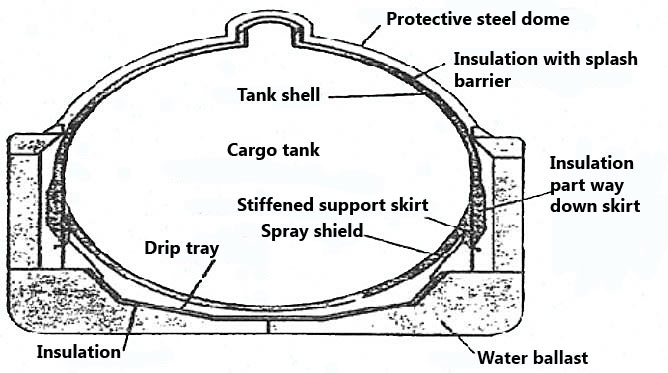
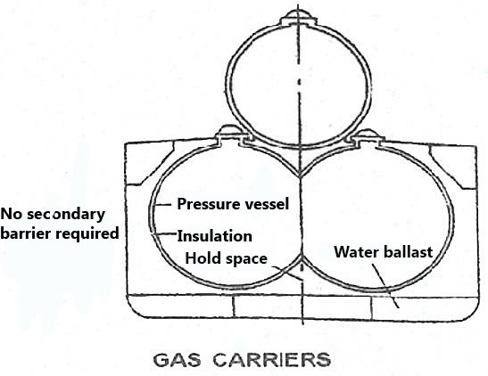
The prevailing design for LNG cargo tanks in the world market is free-standing spherical tanks. Typically, four or five large spherical tanks are placed in line in a ship, each supported by a cylinder or circular ring that is in turn supported by the bottom of the ship’s hull. Spherical tanks have achieved Type B status for LNG shipment under pertinent national and international regulations, by which is generally meant that commercial spherical tanks have been shown by analytical calculations to leak before failing. Current regulations require only a partial secondary barrier, known as a drip tray, for Type B tanks. Spherical tanks, while attractive for fluid storage from the standpoint of maximizing volume-to-surface ratio and from the standpoint of equalizing stresses over the surface, have serious drawbacks as cargo tanks. They have a wall that is sufficiently strong to withstand hydrostatic pressure, which adds weight and increases cost. Spherical tanks typically have a wall thickness in the range of 30-60 mm. Their shape does not match the shape of a ship. Upper portions of the tanks extend approximately 15 m above the main deck. This raises the ship’s center of gravity, increases vulnerability to wind effects, and requires a considerably elevated aft bridge to provide visibility over the tanks. To permit loading from the top, as is required by regulation, considerable access structure must be added above deck-ladders, catwalks, and piping, for example. Operation in high latitudes under winter conditions may be dangerous due to icing high above the deck. Spheres themselves are not free-standing, and so free-standing spherical tanks include a significant support system. Thus, while called «free-standing», in reality spherical tanks are only free-standing if one includes the support system.
Prismatic tanks avoid some drawbacks of spherical tanks. By «prismatic» we mean tanks that are shaped to follow the contours of a ship’s hull. Amidship the tanks may be in the shape of rectangular solids, with six flat sides (four vertical sides, a top side, or top, and a bottom side, or bottom) and with fore and aft vertical sides, or ends, equal. They may also have flat sides that flare outwardly to better match the hull. In other words, the footprint of the tank top and tank bottom need not be of equal size. As used herein, the term, «vertical sides» includes such flared sides. Forward tanks may have a footprint in the nature of a prismatic section (or one-half of a prismatic section, if tanks extend only half way across a ship, in a side-by-side arrangement), with a forward end narrower than the aft end. Aft tanks may also have a footprint in the nature of a prismatic section.
Free-standing prismatic tanks make more efficient use of below-deck volume than do spherical tanks. They avoid high above-deck structure and the associated drawbacks of high center of gravity, wind effects and icing, and consequently have found application in high latitudes such as Alaska. Newer commercial tanks of this type have been shown analytically to meet Type B regulations. However, they contribute significantly to weight and cost due to the fact that free-standing prismatic tanks include heavy plates and a considerable amount of bracing to keep the plates from distorting under hydrostatic load. Prismatic tanks are less efficient than spherical tanks with respect to minimizing surface-to-volume ratio and equalizing hydrostatic load.
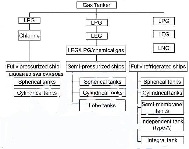
Ship Types for Liquefied Gas Transport
Fully Pressurized Ships
Fully Pressurized Ship’s are the simplest of all Gas Carriers. They carry cargo at ambient temperature, fitted with Type C tanks fabricated in carbon steel, with 18 barg. design pressure. No thermal insulation or reliquefaction plant is necessary.
Because of their design pressure, cargo tanks are extremely heavy, as a result they tend to be small with maximum cargo capacities of about 4 000 m3 and they are primarily used to carry LPG and Ammonia.
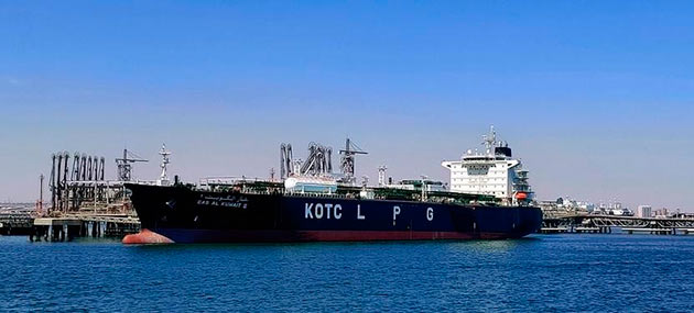
Source: pixabay.com
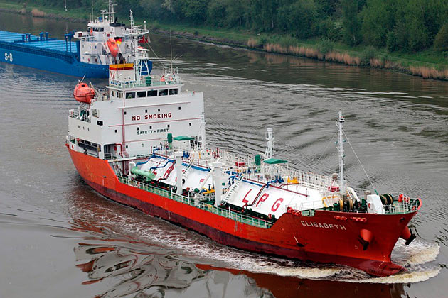
When equipped with a loading heater these ships can load from a fully refrigerated terminal Semi-Pressurized Ships.
Semi Pressurized Ships are quite similar with Fully Pressurized Ships because they are fitted with Type C Tanks. They are designed for maximum pressure of 5–7 barg. With this a reduction of tank thickness is possible but the cost of the reliquefaction plant and tank insulation. They are the optimum means of transporting a wide variety of gasses such as LPG, Vinyl Chloride, Propylene, and Butadiene.
The tanks are usually made of low temperature steels to provide for cargo temperatures of -48 °C which is suitable for most LPG and other chemical gasses. They can also be made from specialized alloyed steels or aluminum for temperatures of -104 °C such as Ethylene. The ships flexible cargo handling system is deigned to load or discharge from both pressurized and refrigerated terminal facilities. These ships are frequently found around the Mediterranean and Northern Europe.
Ethylene Ships
Ethylene Ships are often built for a specific trade but an also carry LPG and other Chemical Gasses. They are normally carried in its fully refrigerated condition at its atmospheric boiling point of -104 °C, with capacities of 1 000-12 000 m3.
A complete double hull is required for all cargoes carried below -55 °C, whether cargo tanks are Type A, B, or C.
Fully Refrigerated Ships
These ships are designed to carry fully refrigerated cargoes at near atmospheric pressure at large quantities, namely LPG, Ammonia and some chemical gasses, butadiene, propylene, and VCM. Four cargo containment system have been used for this type of ships:
- Independent tanks with single hull but double bottom and hopper tanks.
- Independent tanks with double hull.
- Integral tanks (incorporating a double hull).
- Semi-membrane tanks (incorporating a double hull).
The first one mentioned is the most widely used. The tank is Type-A prismatic free standing unit capable of maximum pressure of 0,7 barg. It is constructed of low temperature steel to permit carriage of temperature of about -48 °C. They range in size of about 20 000 m3 to 100 000 m3.
Source: pixabay.com
These ships are normally equipped with 3-6 cargo tanks almost full of the beam of the ship. They are fitted with double bottom tanks together with topside tanks or full side tanks. Type-A cargo tanks are supported on wooden chocks and keyed to hull for expansion and contraction. This type of tanks usually has an internal centerline bulkhead to reduce sloshing. The secondary barrier is normally provided by the use of special steels for all hull structures which maybe exposed to cargo if primary barrier is ruptured. The hold is inerted or filled with dry-air.
It sometimes installed with cargo heaters and booster pumps to allow discharge into pressurized storage facilities so as to improve its operational flexibility.
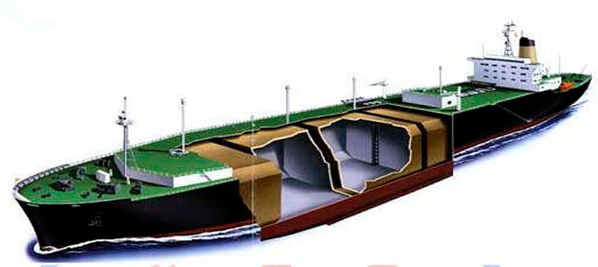
LNG carriers are specialized type of Gas Carriers built to transport large volumes of LNG at its atmospheric boiling point of -162 °C. They are now between 125 000 m3 to 135 000 m3. Cargo containment systems are now mainly of four types:
- Gaz Transport Membrane.
- Technigaz Membrane.
- Kvaerner Moss Spherical-independent Type-B.
- IHI SPB Tank – Prismatic.
All LNG ships are double hulls throughout their cargo length for adequate ballast, and they commonly burn cargo boil-off as fuel. Generally Reliquefation plants have been little used but few have ships have been fitted. Being much colder than LPG, the equipment is more costly and it is more economic to burn boil-off gas in the ship’s main boilers, thus they are commonly fitted with steam turbine engines.
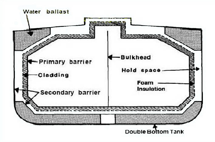
Cargo Containment Systems
A cargo containment system is the total arrangement for containing cargo including, where fitted:
- A primary barrier (the cargo tank).
- Secondary barrier (if fitted),
- associated thermal insulation,
- any intervening spaces,
- and adjacent structure, if necessary, for the support of these elements.
For cargoes carried at temperatures between -10 °C and -55 °C the ship’s hull may act as the secondary barrier and in such cases it may be a boundary of the hold space.
Independent tank type
These types of tank are completely self-supporting and do not form part of the ship’s hull and do not contribute to the hull strength. Depending mainly on the design pressure, there are three different types of independent tanks for gas carriers, Types A (Prismatic), B (Spherical) and C (Cylindrical).
- Type A – commonly found on fully refrigerated LPG, designed pressure is up to 0,7 barg. and constructed primarily of flat surfaces.
- Type B – can be constructed of flat surfaces or spherical type which is commonly found on LNG ships. The containment system is subject to more detailed stress analysis. These controls must include an investigation of fatigue life and crack propagation analysis.
- Type C – tanks are normally spherical or cylindrical pressure vessels having designed pressure higher than 2 barg. Cylindrical vessels may be vertically or horizontally mounted as most commonly found on Pressurized and Semi-Pressurized Gas Carriers. They are designed and built to conventional pressure vessels code and as a result they can be subjected to accurate stress analysis.
Membrane tank type
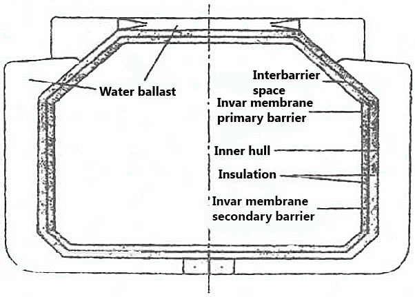
The concept of the membrane system of cargo containment is based on very thin primary barriers, or membranes, which are supported through the insulation by the hull of the ship. They are not self-supporting like the independent tanks outlined in the section above in that inner hull forms the load bearing structure. Membrane containment system must system must always be provided with a complete secondary barrier to ensure the cargo containment system’s overall integrity in the event of primary barrier leakage. The membrane is designed in such a way that thermal or other expansion or contraction is compensated for without undue stressing of the membrane itself.
There are two companies who have developed the system and named them after themselves, Gaz Transport Membrane System and Technigaz Membrane system. They have now merged and future developments can be expected.
Semi-membrane tank type
The semi-membrane concept is a variation tank system. The primary barrier is much thicker than that in the membrane system, having flat sides and large radiused corners. The tank is self-supporting when empty but non-self-supporting in the loaded condition in that the liquid (hydrostatic) and vapor pressure acting on the primary barrier are transmitted through the insulation to the inner hull as is the case with the membrane system. The corners and edges are so designed as to accommodate expansion and contraction.
Integral Tanks
The IMO codes states that «integral tanks form a structural part of the ship’s hull and are influenced in the same manner and by the same loads which stress the hull structure». They further state that integral tanks are not normally allowed if the cargo temperature is below – 10 °C. Certain tanks on a limited number of Japanese-built LPG carriers are of the integral type for the dedicated carriage of butane.
Internal insulation tank type
Sometimes called integral tanks, internally insulated tanks are effectively an integral tank system which utilizes insulation materials fixed to the ship’s inner plating or independent load-bearing surface to contain and insulate the cargo. The con-self-supporting system obviates the need for an independent tank and permits the carriage of fully refrigerated cargoes at carriage temperatures lower than -10 °C.
Internal insulation system have been incorporated in a very limited number of fully refrigerated LPG carriers but the concept has not proved satisfactorily in service.
Survival Capability
The Gas Codes divide gas carriers into four categories, Ship Types 1G, 2G, 2PG and 3G, according to the hazard rating of the cargoes for which the ship is certified to carry. This categorisation can be seen in Appendix 2. For example, Type 1G ships (where the Gas Freeing of Cargo Tanks on Liquefied Natural Gas Carrierscargo tanks are located at the greatest distance from the side shell and may also be restricted in capacity) must be used for cargoes representing the greatest hazard such as chlorine.
Ship Types 2G/2PG and 3G can carry cargoes which represent progressively decreasing environmental hazards and, therefore, progressively less stringent constructional requirements in respect of damage survival capability in the event of collision or grounding.
A fully refrigerated ship, say with Type ‘A’ tanks, designed for LPG must comply with the requirements for tank location and survival capability of a category 2G ship whereas a semi-pressurised ship with Type ‘C’ tanks carrying LPG can comply with the requirements either of a 2G or a 2PG ship.
For the latter case the Type ‘C’ pressure vessels must have a design pressure of at least 7 barg, and a design temperature of not lower than -55 °C. The 2PG category takes into account the fact that the pressure vessel design provides increased survival capability when the ship is damaged by collision or grounding.
The Gas Codes and classification society rules should be referred to for the detailed construction requirements for each category of ship.
1 Type 1G – is a gas carrier intended to transport products indicated in Chapter 19 of the code which require maximum preventive measure to preclude any escape of cargo.
2 Type 2G – is a gas carrier intended to transport products indicated in Chapter 19 of the code which require significant preventive measure to preclude any escape of cargo. LPG of 150 m or more.
3 Type 2PG – is a gas carrier of 150 m in length or less, intended to transport products indicated in Chapter 19 of the Code which require significant preventive measure to preclude escape of such cargo, and where products are carried in independent type C tanks designed for MARVS of at least 7 bar gauge and a cargo containment system design temperature of -550 °C or above. Note that a ship of this description but over 150 m in length is to be considered a type 2G ship.
4 Type 3G – is a gas carrier intended to carry product indicated in Chapter 19 of the Code which require moderate preventive measure to preclude the escape of cargo.
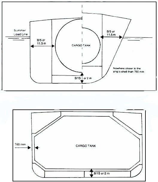
Location of Cargo Tanks in a ship of Type 2G, 2PG and 3G
Tanks, Piping and Valves
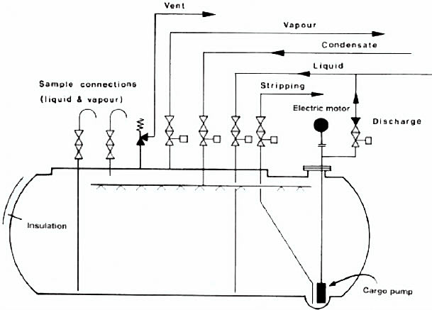
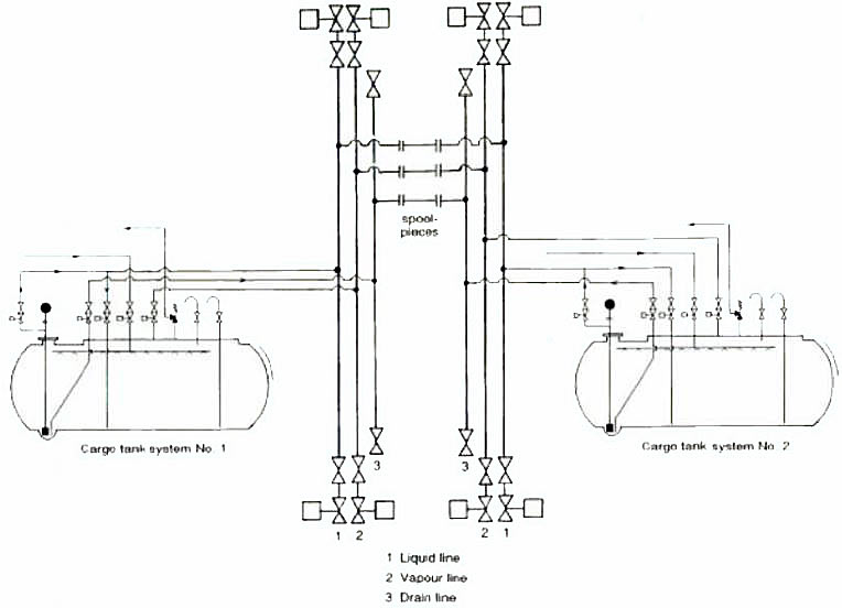
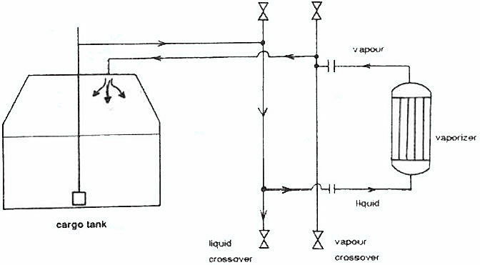
Gas carriers are normally fitted with liquid and vapour manifolds situated amidships. These are connected to liquid and vapour headers- or pipelines with branches leading into each cargo tank. The liquid loading line is led through the tank dome to the bottom of each cargo tank; the vapour connection is taken from the top of each cargo tank. On semi-pressurised and fully refrigerated LPG ships a vapour connection is taken from the vapour header to the cargo compressor room where reliquefaction of the boil-off takes place. After reliquefaction the cargo is piped, via a condensate return line, to each cargo tank. In the case of LNG ships the boil-off vapours are usually fed to the ship’s boilers, via a compressor and heater, for use as main propulsion fuel.
Cargo pipelines are not allowed beneath deck level on gas carriers; therefore, all pipe connections to tanks must be taken through the cargo tank domes which penetrate the main deck. Vapour relief valves are also fitted on the tank domes; these are piped, via a vent header, to the vent riser. The vent risers are fitted at a safe height and safe distances from accommodation spaces and other such gas-safe zones as specified in the Gas Codes.
Provision must be made in the design and fitting of cargo pipelines to allow for thermal expansion and contraction. This is best achieved by the fitting of expansion loops or, by using the natural geometry of the pipework, as appropriate. In a few specific cases, expansion bellows may be fitted and, where this is planned, corrosion resistant materials should be used and Section 5.3.2.2 of the IGC Code should be considered. Where expansion bellows are fitted in vapour lines, it should be ensured that their pressure rating at least meets the liquid pipeline design criteria.
Furthermore, expansion bellows often attract considerable maintenance while a ship is in service- in particular, sea-water corrosion must be carefully avoided otherwise pin hole leaks are liable to develop. It is also important not to alter or adjust adjacent pipeline supports once the ship has entered service since they form an integral part of the expansion arrangements.
Furthermore it should also be noted that parts of pipeline systems are fitted with strong anchor points to resist lateral or vertical displacement from surge pressures. Similarly, when replacing parts such as bolts and restraining rods, care must be taken to ensure that the new parts are of the correct material for the service. Removable spool pieces are taken in or out of pipelines to interconnect sections of line for special operational reasons such as using the inert gas plant or ensuring segregation of incompatible cargoes. These spool pieces should not be left in position after use but should be removed and pipelines blanked to ensure positive segregation.
Cargo valves and strainers
Isolating valves for cargo tanks must be provided in accordance with Gas Codes. Where cargo tanks have a MARVS greater than 0,7 barg (Type ‘C’ tanks), the principal liquid and vapour connections on the tank dome (except relief valve connections) should be fitted with a double valve arrangement. This should comprise one manually operated globe valve and a remotely operated isolation valve fitted in series. For Types ‘A’ and ‘8’ cargo tanks (with the MARVS less than 0,7 barg) the Gas Codes allow single shut-off valves for liquid and vapour connections. These valves can be remotely actuated but must also be capable of local manual operation. Remotely operated emergency shut-down valves are provided at the liquid and vapour manifolds for all gas carriers.
The types of isolation valve normally found on gas tankers are ball, globe, gate or butterfly valves. These valves are usually fitted with pneumatic or hydraulic actuators. Ball valves for liquefied gas service are provided with a means of internal pressure relief. This is usually a hole drilled between the ball cavity and the downstream side of the valve. Valves must be of the fail-safe type.
In the LNG trade strainers are commonly provided at the manifold connections for loading and discharging. It is important not to bypass these strainers. Furthermore, they should be frequently checked and cleaned. The strainers are installed to protect cargo handling equipment from damage by foreign objects. Many strainers are designed for one-way flow only.
Ships Equipment and Cargo Instrumentation
Instrumentation
Instrumentation is an important part of gas tanker equipment and is required for the measurement of cargo level, pressure and temperature. It is also used for gas detection. Instrumentation must be carefully selected and well maintained.
Liquid level instrumentation
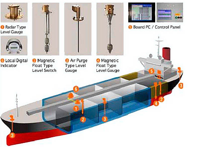
The Gas Codes and classification society rules require every cargo tank to be fitted with at least one liquid level gauge. Specific types of gauging system are required for certain cargoes as defined in Chapter 19 of the IGC Code. This information is summarised in Appendix 2.
The IMO classification for gauging systems is as follows:
- Indirect systems – these may be either weighing methods or flow meters.
- Closed devices which do not penetrate the cargo tank – here ultrasonic devices or radio isotope sources may be used.
- Closed devices which penetrate the cargo tank – such as float gauges and bubble tube indicators.
- Restricted devices which penetrate the tank but which release small volumes of liquid or vapour to atmosphere when in use, such as fixed or slip-tube gauges. When not in use, the restricted device should be kept completely closed.
In the LPG trade the most common types of level gauging are the last two described, while in the LNG trade, the closed devices are more usual.
Float Gauges – are widely used onboard Gas Carriers. It consists of a float attached by a tape to an indicating device which can be arranged for local and remote readout. They maybe also fitted with guide wires, and gate valves for isolation so it can be serviced in a safe atmosphere.
Particular attention should be drawn to the following:
- The float must be lifted when not in use, if let down especially when fully loaded, liquid sloshing might damage the tape tensioning device.
- Remote and local reading should be compared frequently to detect/determine discrepancies, corrections for trims and list etc. should be applied.
- Tapes should be checked for free vertical movement of the float and obstructions. If such problems should occurs repair or replacement should be carried out as the rewind mechanism are carefully balanced thus making readings inaccurate.
- During maintenance, if tapes are renewed, and gauges are reassembled, allowance should be made for the level at which the float begins to float. This is dependent to the cargo density which the float will be used. See manufacturer’s instructions for details.
- Parts should be securely locked in position especially at the tap-to-float and tape-toreel attachments.
Nitrogen Bubbler Gauges – measures the pressure necessary to displace a liquid cargo from a small bore tube mounted vertically in a tank. A sufficient pressure of nitrogen is introduced into the tube to displace the liquid and to commence bubbling at the bottom. The pressure necessary to do this measured, which is the function of the liquid level and liquid density. For cargoes of known density, level read out is obtained directly.
Gas flow rate to the system should be kept low to avoid back pressure thus giving inaccurate readings. Any leaks in the sensing pipe will cause inaccuracy and therefore all joints and glands should be checked regularly.
The use of such instruments is not recommended for carriage of ethylene cargo. Ethylene has such restrictions for contamination by nitrogen thus such equipment might damage the cargo.
Differential Pressure Gauges – are commonly used on shore terminal tanks. It operates on pressure difference between the liquid and vapor pressures. The signal lines are normally purged with inert gas. This type can be used on vessels whose cargo tanks are completely located on deck.
Capacitance Gauges – uses intrinsically safe electrical circuits. They measure the change in electrical capacitance between two probes, as cargo liquid, rather vapor, takes up the space between them. The tube extends throughout the depth of the tank and provides a continuous indication of liquid content at all levels.
This device has no moving parts are usually much reliable but must be kept clean and free from dirt, rust, water and ice since such contaminants can cause inaccuracy in readings.
Slip-Tube and Fixed Tube Gauges – this type of gauging system is of restricted type, it means a small amount of cargo vapor or liquid is released during measurement. Some terminal does not allow the use of such equipment especially for certain type of cargoes which causes harmful effects to personnel working nearby.
This type can be used for pressurized vessels. The tubes lower end is opened to the cargo tank and penetrates it. It slides up and down through a gland fitted in the tank dome. Since small amount of cargo is released during measurement this devices is limited as a back-up for of closed devices and to Type C tanks only.
Every cargo tank must be fitted with an Independent High Level alarm sensor giving visual and audible alarms. The Float, Capacitance or Ultrasonic sensors can be utilized for this purpose. The High level alarm or independent sensor is required to automatically stop the flow of cargo into the tank. (Automatic Shutdown System).
The Automatic Shutdown System requires particular care to avoid pressure surge. Valves, stopping the flow of liquid during high rates of loading could cause significant surge pressure. Thus great care is taken to ensure that the activation points are set accurately and checked by simulation whenever necessary. If the ship-shore shutdown system can be linked, their operation should be checked before the start of cargo operation begins, if not the terminal should be informed of the closing rate of the ships valves.
Pressure and Temperature Monitoring System
Pressure and Monitoring Systems are required by the Gas Codes. They are required throughout the cargo system, which includes cargo tanks, pump discharge lines, liquid and vapor crossovers. Pressure switches are also fitted to various systems to protect personnel and equipment by operating the alarms and the shutdown systems.
The Gas Codes also requires Pressure and Temperature within the insulation or hull structure adjacent to the cargo containment system and the cargo containment system itself. The indicators are set to provide adequate warning for the lowest temperature for the hull steel to be approached thus preventing undue thermal stress, for the cargo containment system it is very useful for monitoring the tanks while warming-up or cooldown operations.

General precautions for pressure sensing equipments:
- Materials of construction should be compatible with the cargo (ex. Copper or brass cannot be used for ammonia).
- Before measurements are taken all valves in the direct line should be opened and cross connections shut.
- No pressure gauges should be subjected to pressure surge.
- Calibration should be regularly checked with accurate test equipment.
- In ships carrying cargoes which can form polymers such as butadiene, it maybe necessary to flush gauge lines and sensor chambers.
- If sensor lines are temporarily disconnected during maintenance they should be blanked.
General precautions for temperature reading devices:
- The thermometers used should be suitable for the complete range of temperatures expected.
- The sensor should make good thermal contact with the material whose material temperature is to be measured.
- If the readings do not change when expected, the instrument should be checked.
- Thermometers, especially those with capillary tubes, are easily damaged: they should be handled with care and protected from mechanical damage and extremes of temperature beyond their scales, otherwise they become inaccurate.
- When a thermometer is removed from its working location, care should be taken to avoid loosening or removing its pocket, especially if the system is pressurized.
- When it is fitted in a working location, care should be taken that it does not bottom in the pocket when screwed in as this could cause damage: if the bulb is slack in the pocket a material with high thermal conductivity can be used to ensure accurate readings.
- Electrical connections should be clean, tight and correct: care should be taken to see that intrinsically safe leads are not cross connected with ordinary power source.
General precautions:
- The device should be correctly calibrated over its full range using accurate test instruments.
- If the set point of the device is fixed, it should be locked to prevent disturbance from vibration or tampering.
- If the set point is adjustable, no changes should be made unless the full implication are understood and other operators are advised: adjustment should be made under the direction of a responsible personnel and in accordance with the cargo carried.
- If shut-off cocks are fitted, they should be open during normal operations: no additional shut-off cocks should be fitted.
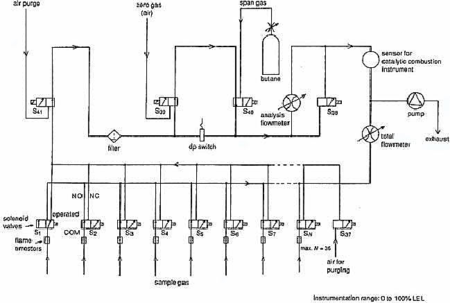
Gas Detection Systems
The Gas Codes requires Gas Carriers to have Fixed Gas Detection Systems with audible and visual alarms onboard. These should be fitted at the wheelhouse, cargo control room and at the gas detector read out location. The following are the spaces normally provided with gas detectors:
- Cargo Compressor Room.
- Electric Motor Room.
- Cargo Control Room.
- Enclosed Spaces such as hold spaces and interbarrier spaces (except Type C tanks).
- Air Locks.
- Burner Platforms vent hoods and engine room gas supply pipelines (LNG only).
A number of functions required by the Gas Codes are the following:
- Detecting cargo vapour in air, inert gas, or the vapour of another cargo.
- Measuring concentrations of gas in or near the flammable range.
- Measuring concentrations of oxygen in inert gas or cargo vapour, or in enclosed spaces.
Cargo Pumps
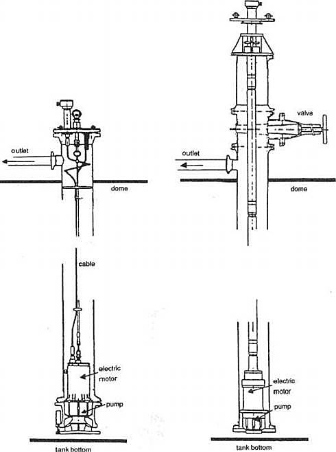
Deepwell Pumps – are the most common pump for LPG Carriers, they might be driven electrically or hydraulically (through a sealing arrangement) by a motor which is mounted outside the tank. The drive shaft is held in a carbon bearing inside the cargo discharge tube and the bearings are cooled by the cargo flow itself.
The Centrifugal Impeller is mounted at the bottom of the cargo tank and frequently comprises of two to three stages together with the first stage inducer. Shaft sealing consist of a double mechanical seal flushed with lubricating oil at the cargo tank dome. The accurate alignment of the motor coupling, thrust bearing and mechanical oil seal is important. Further more, the length of the drive shaft can be problem, as the length of becomes longer the more support is needed.
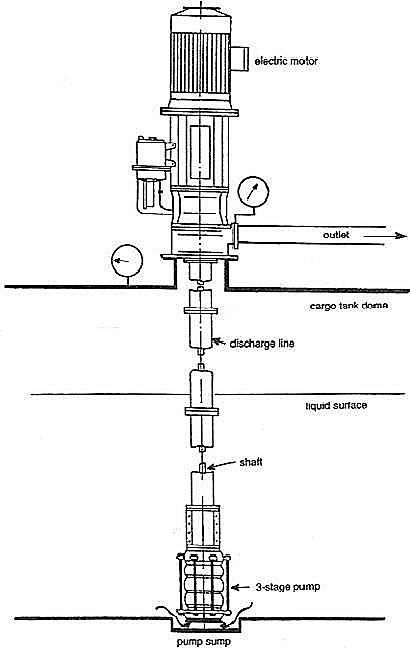
Submerged Motor Pumps – are installed at the bottom of the cargo tanks and enables very low pump levels to be achieve. They are commonly fitted on all LNG Carrier and some larger LPG. The pump and motor are mounted integrally on the same shaft thus eliminating the need for mechanical seal or coupling. Power is supplied by specially sheathed cables, commonly of copper or flexible stainless steel armored insulated power cables.
These pumps are cooled and lubricated by the cargo itself, therefore are prone to damage due to loss of flow. Accordingly the pump is protected by safety devices such as an under-current relay, a low discharge pressure switch, or a low tank level switch.
Read also: LNG Carrier Pressure Relief Systems
For these pumps to be used for ammonia, which is an electric conductor and can be a corrosive cargo, they fitted with electric stator or «canned» in stainless steel, which is very thin and great care is needed to avoid damage.
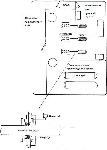
Booster Pumps – are pumps which are centrifugal type. They maybe vertically or horizontally mounted on deck in appropriate discharge line.
They may be also fitted at the compressor room, but when fitted, they are driven in through a gas-tight bulkhead by an electrical motor installed in the electric motor room. Their main purpose is to increase the discharge pressure from another pump commonly the cargo pumps.
Reliquefation Plant and Boil-off Control
Reliquefaction Plant and Boil-Off Control System are necessary for most Gas Carriers, during voyage and cargo operations in port. With the exception of fully pressurized ships, most LPG and Chemical Gas Carriers are fitted with this system.
Their main functions are the following:
1 To cool down the cargo tanks and necessary pipelines prior to loading.
2 To reliquefy the cargo vapor or boil-off gas generated by flash evaporation and liquid displacement during loading.
3 To maintain cargo temperature and pressure during sea passage within prescribed limits.
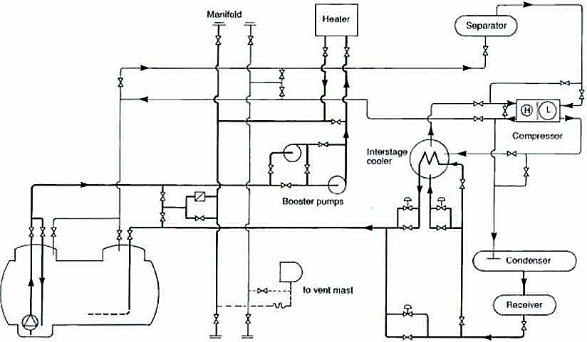
A simple Reliquefaction Cycle is comprised of the following:
1 Cargo Tank.
2 Compressor.
3 Condenser.
4 Expansion Valve.
There are two main types of reliquefaction plant:
1 Indirect cycles – Indirect Cycle or Cooling is used for cargoes which for chemical reasons cannot be compressed. This system uses an external refrigeration plant to condense the cargo vapor without being compressed. It requires, for efficiency, a very cold refrigerant in the condenser and a large surface for heat exchange. Common refrigerant used are Hydrogen, Helium and Propane.
This type of reliqufaction plant is required by the Gas Code when carrying Chlorine, Ethylene Oxide, Ethelyne Oxide – Propylene Oxide Mix, Propylene Oxide Mix.
2 Direct cycles – This is the most common system onboard Gas Carriers but may not be suitable for other gasses as per IGC Code. This is a system where the boil-off gas is compressed, condensed and returned to the tank.
There are three types of Direct Cycle:
I Single Stage Direct Cycle – is suited onboard semi-pressurized ships which carries high boiling point cargoes.
II Two Stage Direct Cycle – is suited for Gas Carriers handling a wide range of products such as Butadiene and Vinyl Chloride, where such fitting or system is essential. If the compressor discharge-to-suction ratio in single stage cycle exceeds 6:1, meaning too much discharge and less suction, then the efficiency of the compressor is lessened, thus the need for the two stage cycle. This system utilizes an Intercooler to reduce the suction pressure of the second compressor to increase efficiency, this is essential for cargoes such as fully refrigerated Ammonia.
III Cascade Direct Cycle – is mainly used for refrigerated cargoes. It utilizes a refrigerant such as R22 (monochlorodifluoromethane) to cool the condenser, thus obtaining lower temperatures. The cargo, when condensed, evaporates the refrigerant R22 and the R22 vapor is compressed, condensed in a conventional R22 closed refrigeration cycle using sea water – hence the term Cascade or «to flow» is used.
Cargo Compressors
The Cooldown of Cargo System on the Liquefied Gas CarriersCargo Compressor is the heart of the Reliquefaction Plant. They are used for cargo reliquefaction, vapor supply to and from the shore, gas freeing, and for LNG ships to supply vapor to the engine room. As for LPG ships there are two main types, the reciprocating type and the screw type. Operations and maintenance should be readily available from the manufacturer’s handbook.
The following are types of compressors:
1 Reciprocating Compressors – two types of reciprocating compressors may be found, conventional compressors and oil free compressors. They are used mainly in reliquefaction plant for the compression of refrigerant gasses or cargo vapour. If used with refrigerants, the considerations application to normal refrigeration plant should be observe. If used with cargo vapour, special precautions may be necessary, depending on the cargo.
Conventional Compressors have a conventional crankcase and the cargo vapour comes into contact with the lubricating oil. Two additional precautions to be observe, therefore, are to ensure that oil separation equipment is working properly and kept clean, with oil levels being monitored: and be aware that cargo vapour may condense in the crankcase and dilute the oil, requiring heaters, if fitted to be used.
In oil-free compressors vapour and oil do not come into contact with each other and therefore cargo contamination is avoided. Two additional precautions are to be observed are that cooling system should be inhibited t prevent corrosion or freezing, and that crankcase cylinder assembly seals should be kept in good condition to prevent contamination between cargo and lubricating oil (usually mechanical seals which require careful maintenance).
2 Centrifugal Compressors – these are normally single or multi-stage impellers driven at high speed by a steam turbine through a gearbox. They are often used on LNG ships for vapour supplies to the engine room or the shore.
Automatic surge controls are normally fitted to keep the flow rate above the set point, living a factor of safety over the maximum operating limits. The differential pressure across the compressor is sensed and when the set point is approached the discharge vapour is returned to the suction to prevent reversal. It is most important that surge controls functions reliably. They should be recalibrated after maintenance according to manufacturer’s instructions.
3 Rootes-type Compressors – these are positive displacement machines with two mating lobe-shaped rotors. Compression ratios are comparatively small giving a pressure increase of about 0,5 bar.
The following precautions should be observed:
- clearance between moving parts and casings are very small and the passage of solids (ex. rust or weld slag) or liquid will cause damage: filters and liquid separation equipment must be well maintained;
- if subjected to a pressure differential when stopped the rotors will turn: a non-return valve is usually fitted to prevent reverse rotation which could occur without lubrication: when compressors are stopped the suction and delivery valves should be closed;
- compressors should never be run with the discharge valve shut, otherwise over-heating and mechanical failure could occur.
4 Screw Compressors – theses are positive displacement high speed compressors with mated screw rotors.
The following precautions should be observed:
- Filters must be kept in good condition because internal clearances are very fine and the passage of solids (ex. rust or weld slag) will cause damage.
- Liquids should not be allowed to pass through compressors design handle vapours only.
- Compressors should not be operated with the discharged valves closed.
Cargo Heaters/Vaporizers
Heat Exchangers may be fitted for any of the following purposes:
- as Vaporizer (for cargo or nitrogen);
- as Heaters (for liquid vapor);
- as Condensers (for cargo vapor or refrigerant gas);
- as Driers (for inert gas, cargo vapor or compressed air);
- as Intercoolers (in refrigeration plant);
- as Coolers (for water or lubricating oil).
Cargo Heaters are typically designed to raise fully refrigerated propane from -45 °C to -5 °C by the use of sea water as heating medium. The conventional horizontal shell and tubes type exchanger is commonly used. Sea water is passed through the tubes while the cargo is passing around the tubes.
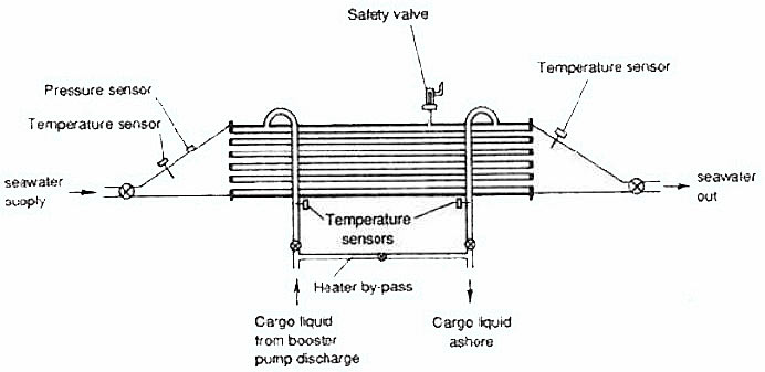
When discharging refrigerated cargoes into pressurized shore storage, it is usually necessary to heat the cargo to avoid low-temperature embrittlement of the shore tanks and pipelines. It should be noted that it is very difficult to control the cargo flow rate, as the temperature to be achieved maybe significantly reduced in cold sea water areas. Low discharge rate is may be possible but if the seawater temperature fall below 5 °C it becomes increasingly difficult to use it as a heating medium. Cargo vapor from liquid is also often required on gas carriers. They maybe needed to gass-up the cargo tanks or to maintain cargo tank pressure during discharge, specially if vapor return line from shore is not available.
Relief Valves
Two pressure relief valves are required by the Gas Codes. They should be of equal capacity fitted to any cargo tank of greater than 20 cubic meters capacity. One valve is sufficient if capacity is less.
The following devices may be fitted:
- Spring loaded relief valves;
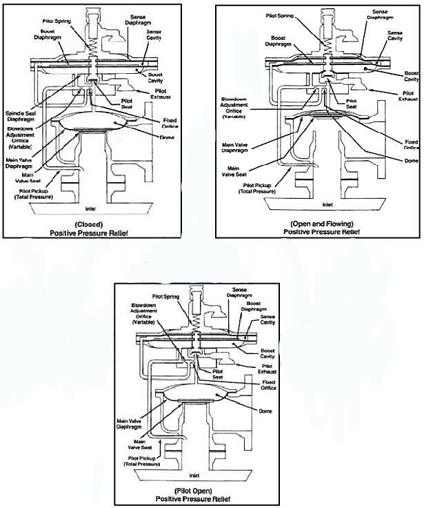
- Pilot operated relief valves;
- Deadweight relief valves;
- Bursting disc.
Pilot operated relief valve can be found on all tank types while the spring loaded relief valve are usually used only on Type “C” tanks. Pilot Operated relief valve which are commonly found on most ships when fitted on fully refrigerated tanks ensures accurate operations at the low-pressure condition, while at Type “C” tanks, they can be adjusted to variable relief settings. This may be done by changing the pilot-spring.
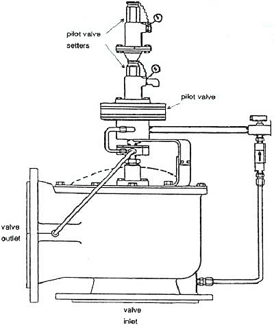
Spring Loaded and Pilot Operated relief valves are precision made devices often having small delicate components (ex. needle valves or thin spindles) and care should be taken to prevent damage at all times.
Inert Gas and Nitrogen System
Unlike most Oil Tankers with extensive requirements for the Inert Gas System, the Gas Codes have limited advice on the fitting of such system onboard, special considerations are made by the administrations and the particular demands of the trade of Gas Carriers.
These are various forms of Inert Gas System that Gas Carriers utilizes:
- Inert gas from combustion-type generators.
- Nitrogen from shipboard production systems.
- Pure Nitrogen taken from shore.
The onboard Combustion type Inert Gas System cost less than purchasing Liquid Nitrogen and Inert Gas is readily available either at sea or in port.
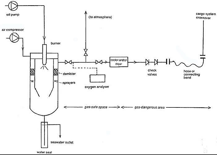
The disadvantage of the Combustion type is the quality of the gas produced. The preferred quality of the fuel used must be of low sulphur content thus careful combustion of diesel or gas oil is adjusted to avoid production of toxic carbon monoxide and soot. This produces reduced oxygen content in the inert gas.

- The international group of liquefied natural gas importers (GIIGNL). LNG custody transfer handbook / 6th Edition: 2020-2021.
- American Gas Association, Gas Supply Review, 5 (February 1977).
- ©Witherby Publishing Group Ltd. LNG Shipping Knowledge / 3rd Edition: 2008-2020.
- CBS Publishers & Distributors Pvt Ltd. Design of LPG and LNG Jetties with Navigation and Risk Analysis / 4th Edition.
- NATURAL GAS PROCESSING & ITS ENERGY TRANSITION ROLE: LNG, CNG, LPG & NGL Paperback – Large Print, November 14, 2023.
- American Gas Association, Gas Supply Review, 5 (February 1977).
- The Society of International Gas Tanker and Terminal Operators (SIGTTO). Ship/Shore Interface / 1st Edition, 2018.
- Federal Power commission, Trunkline LNG Company et al., Opinion No. 796-A, Docket No s. CP74-138-140 (Washington, D. C.: Federal Power Commission, June 30, 1977).
- Federal Power Commission, Final Environmental Impact Statement Calcasieu LNG Project Trunkline LNG Company Docket No. CP74-138 et al., (Washington, D. C.: Federal Power Commission, September 1976).
- Federal Power Commission, «FPC Judge Approves Importation of Indonesia LNG».
- Federal Power Commission, «Table of LNG imports and exports for 1976», News Release, June 3, 1977, and Federal Energy Administration, Monthly Energy Review, March 1977.
- Office of Technology Assessment LNG panel meeting, Washington, D. C., June 23, 1977.
- Socio-Economic Systems, Inc., Environmental Impact Report for the Proposed Oxnard LNG Facilities, Safety, Appendix B (Los Angeles, Ca.: Socio-Economic Systems, 1976).
- «LNG Scorecard», Pipeline and Gas Journal 203 (June 1976): 20.
- Dean Hale, «Cold Winter Spurs LNG Activity»: 30.