Natural gas storage tanks are containers used to store natural gas in a safe and secure manner. They are typically made of steel or composite materials and are designed to hold the gas under pressure.
- General
- Storage under pressure at ambient temperature
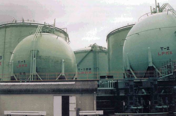
- Spherical and horizontal cylindrical tanks above ground
- Mounded horizontal cylindrical tanks
- Underground caverns
- Storage in semi-pressurised spheres
- Storage at atmospheric pressure in refrigerated condition
- Different types of refrigerated storage tanks
- Different types of containment systems
- Standard for low temperature cylindrical vertical storage tanks
- Materials used for low temperature storage tanks
- Evolution of the size of shore storage tanks
- Some possible incidents in liquefied gas shore storage tanks
- Rollover
- Fire hazard
- Boiling Liquid Expanding Vapor Explosion (BLEVE)
These tanks are essential for ensuring a continuous and reliable supply of natural gas to consumers. The development of liquefied natural gas (LNG) production in Russia opens up a promising market for storage tanks
General
Liquefied hydrocarbon gases require storage facilities ashore, both at the production end and at the distribution end. Storage is required at the production point so that the plant can continue production while waiting for the ship which will transport the gas. It is also required at the distribution point, to allow the ship to discharge its full cargo and return to the loading port without delay, to store the product pending its regular use and to keep a sufficient inventory ready for a period of high demand and higher selling price. Some countries, like Japan, also keep a strategic stock of liquefied gas to guarantee continued availability in case of possible interruption of supply.
In the early years, shore storage tanks held products at ambient temperature in pressurised conditions. For reasons similar to those explained earlier with regards to the ships, pressurised shore tanks were of simple design and small capacity.
The development of transport in fully refrigerated condition and the consequent increase in the size of ships meant that shore tanks had to become much larger and so different construction techniques evolved for cryogenic shore tanks. It started with the single containment tank, followed by the double containment tank and the double integrity or full containment tank and the membrane tank. Large capacity underground storage for LPG was also developed. More recently, the very rapid growth of the LNG trade gave further opportunity for the construction of very large above-ground and in-ground tanks.
The development of shore storage tanks has been further driven by the concerns of regulatory agencies and large consumers for safety and environmental considerations. There have been, through the years, several accidents which, unfortunately, resulted in the total destruction of plants and loss of human lives. These accidents have shown that fire hazards are the greatest risk and that the location and fire protection of Level Gauging Systems in Liquefied Gas Tanksliquefied gas tanks should be carefully evaluated.
Storage under pressure at ambient temperature
Storage in these conditions can be provided in the following tanks:
- Spherical or horizontal cylindrical tanks above ground, for LPG and chemical gases.
- Mounded horizontal cylindrical tanks, mostly for LPG.
- Underground storage caverns for LPG.
Spherical and horizontal cylindrical tanks above ground
These tanks are used at:
- refineries;
- chemical plants;
- small or medium size import and export terminals;
- industrial;
- bottling plants, etc.
They can accommodate LPG and the full range of chemical hydrocarbon gases, as well as ammonia. Pressurised tanks are of small capacity when compared to large refrigerated. The largest pressurised spheres can only have a capacity up to 5 000 m3, but it is possible to create storage plants of reasonable size by grouping a number of spheres or cylindrical tanks.
The design and construction of pressurised tanks must follow recognised pressure vessel codes, such as British Standard BS 5500 or American Standard ASME Boiler and Pressure Vessel Code Section VIII. Each tank must be equipped with at least one pressure relief valve connected directly to the vapour space, a level gauge, pressure and temperature indicators and a high level alarm adjusted to the maximum permissible level.
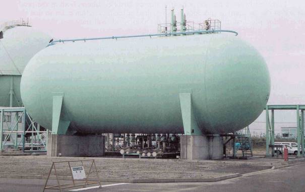
The lay-out of the storage area must be such that, even if the product should leak from one tank and ignite, it will not put at risk other tanks or equipment in the storage area or people and industrial equipment in adjacent areas.
Following a small number of very spectacular accidents, the storage of liquefied gas is now subject to stricter controls. In Europe, the amended «Seveso Directive», covering major hazard sites, requires the distances previously allowed between each storage tank within the plant and between the plant and other industrial areas and public facilities to be increased. It also gives guidance on the complete lay-out of the plant, the type of fire-fighting equipment required and specifies that each tank must be easily accessible for fire-fighting.
Mounded horizontal cylindrical tanks
Most countries specify that pressurised horizontal cylindrical tanks above a certain size are no longer allowed to be installed above ground. Some countries do not allow tanks of this type to be installed above ground at all. They must be mounded under earth cover protection. The earth cover protects them from being engulfed by flames or from the heat of an adjacent fire so that the BLEVE form of catastrophic failure is impossible. Minimum distances between each tank or group of tanks are specified.
Another advantage of mounded tanks is protection from sun radiation which reduces the rise of the product temperature. One disadvantage, however, is the difficulty to protect tanks against corrosion and to inspect their external parts.
Certain countries specify a maximum size for pressurised spherical tank in order to reduce the risks in case of fire. Each gas storage vessel and every bulk loading or discharge facility must be provided with a fire-protection system, which will ensure that tanks maintain their structural integrity under fire conditions. This can be by location, insulation or by the use of cooling water. All above-ground pressure tanks must be protected by fixed spray-water systems.
Underground caverns
Pressurised LPG may also be stored in underground caverns, either leached from salt deposits or mined from rock formations. The caverns are set at a depth sufficient for the head of the water-table to be greater than the pressure of the stored product. Leakage of products into the rock strata is prevented by the pressure surrounding the cavern. The inflow of ground water is collected and pumped to the surface. The stored product is discharged from the cavern by means of submerged pumps. This is a very safe way of accommodating large quantities of products and a number of very large mined underground caverns have been created in recent years.
Storage in semi-pressurised spheres
Spheres for the storage of semi-preasurised LPG, chemical hydrocarbon gases and ammonia can accommodate up to 5 000 tonnes of cargo at temperatures as low as -50 °C. The spheres must be insulated and the internal pressure must be controlled by means of a reliquefaction plant. They present a much reduced risk in case of fire compared to the pressurised spheres. This is due to their lower operating pressure and the good protection against radiation from any adjacent fire, provided by the insulation. These semi-pressurised spheres can be found in much the same places as pressurised tanks and are a choice containment for chemical gases which have to be kept at low temperature.

Storage at atmospheric pressure in refrigerated condition
Different types of refrigerated storage tanks
There are three main groups of refrigerated tanks for LPG, ethylene and LNG:
- Above-ground tanks. This is the original type of refrigerated tank. They may be single containment, double containment or double integrity or full containment. These tanks may be used for LPG, ethylene or LNG.
- In-ground tanks. The in-ground tank consists of a concrete ring section covered with insulation and a stainless steel or Invar membrane. These tanks are expensive to construct and are generally used for LNG.
- In-pit or semi-buried. This is a hybrid of the two previous types, usually double integrity or full containment type and mainly used for LPG and LNG.
a) Above-Ground Tanks – Above-ground tanks were originally developed for oil storage. It is by far the most common type of refrigerated tank in use for liquefied gases. The first cylindrical tanks of this type to be built for liquefied gases were commissioned in the late 1950’s for the Algeria-UK and Algeria-France LNG projects. Since then, many similar tanks of varying sizes have been built for LPG, ethylene and LNG.
The tank sits on a foundation slab, which may be in contact with the ground or supported on piles, allowing an air gap underneath. If the slab is in contact with the ground, a heating system must be provided to prevent the ground from freezing. This could make the ground heave and so damage the tank foundations.
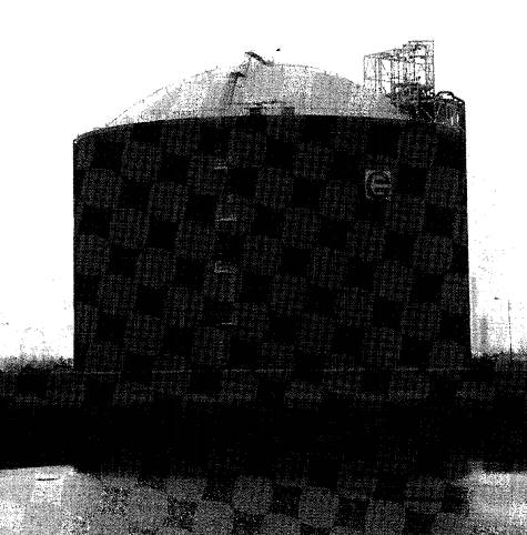
This type of tank can accommodate single containment, double containment or double integrity or full containment systems. They are simple and reasonably cheap to build and benefit from the considerable experience gained in the construction of traditional oil storage tanks.
The down side is that they are highly visible, which can raise environmental problems. The possibility of liquid spillage in case of catastrophic failure, their vulnerability to radiant heat in case of adjacent fire and possible missile damage are other potential concerns.
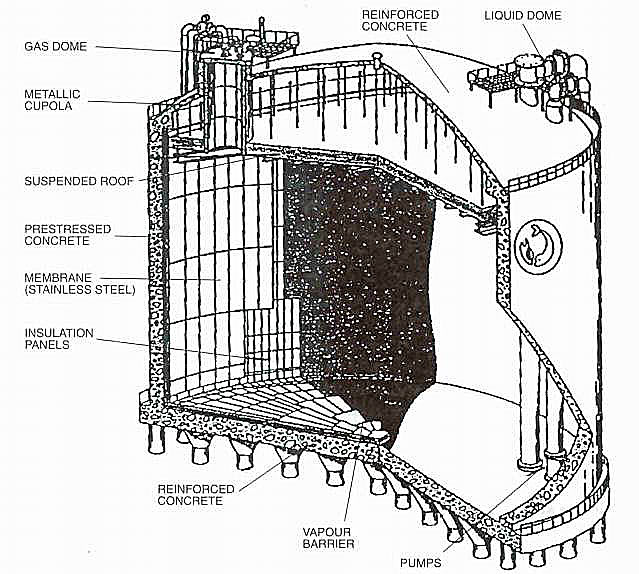
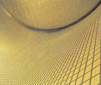
b) In-Ground Tanks – In-ground tanks are built within a ring section made of reinforced concrete reaching deep underground to the watertight clay or rock level. The bottom of the tank is also reinforced concrete. Load-bearing insulation lines the concrete wall and supports a membrane which can be a «flat» sheet of Invar or a «corrugated» sheet of stainless steel ASTM 304A, in accordance with the Gaz Transport or Technigaz techniques previously described in Various Types of Liquefied Gas Tankers“Characteristics and Types of Liquefied Gas Tanker” (LNG LPG). Very few tanks have been built using the Gaz Transport technique, but a large number use the Technigaz technique, or similar, adapted by Japanese constructors. The top of the tank can be carbon steel or concrete supporting the insulation. There is a gas-tight seal with the side membrane making a gas-free insulation space which can be monitored for leakage in the membrane.
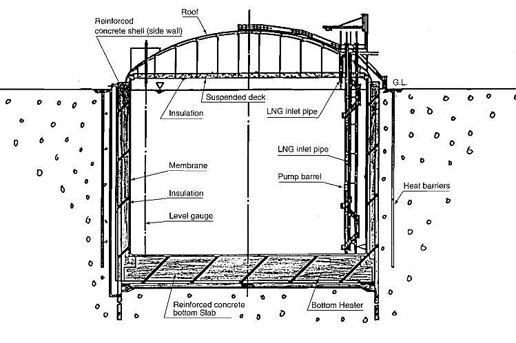
This type of tank is very expensive to build and is generally used for storing LNG. It is extensively used in Japan and Korea as it is well protected against earthquakes. Due to the low level of the tank roof, it is also quite inconspicuous.
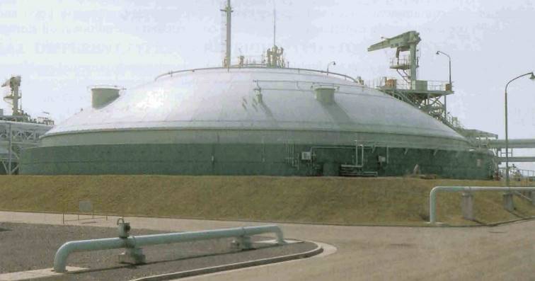
Early examples of under-ground tanks built in Europe and Algeria had no membrane or insulation, relying on frozen clay to contain the LNG. This was not successful as it resulted in advancing frozen ground, creating serious ground heave. Those tanks were decommissioned after less than ten years’ operation and much time and cost were spent on heating and cleaning the contaminated areas.
Later tanks had heating systems installed both around the concrete skirt and under the tank bottom. The largest tank of this type has recently been commissioned in Japan, with a capacity of 200 000 m3.
The membrane operations advantage of this type of tank is a very high level of safety. The unstressed prevents possible crack propagation and allows for rapid cool-down/warm-up if required. There is no possibility of catastrophic liquid spillage due to containment failure, a good protection against earthquakes, discreet sighting, low exposure to radiant heat in case of adjacent fire and less exposure to impact. There is no limit to the possible tank size.
The disadvantages are duration and high cost of construction and the need to maintain the heating system at all times.
c) In-Pit or Semi-Buried Tanks – These tanks are a compromise between the above ground type and the in-ground type. They present better safety protection than the above-ground and they are not as expensive to build as the in-ground tanks.
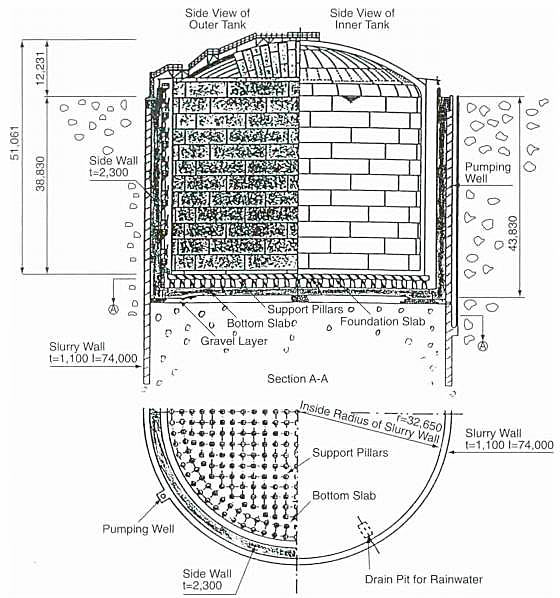
Catastrophic failure with large release of liquid would not be possible with semi-buried type tanks and this type of tank presents good protection against adjacent fire radiation. They would, however, not be as well protected as the Prevention rollover in LNG Tanksin-ground tanks in case of earthquake.
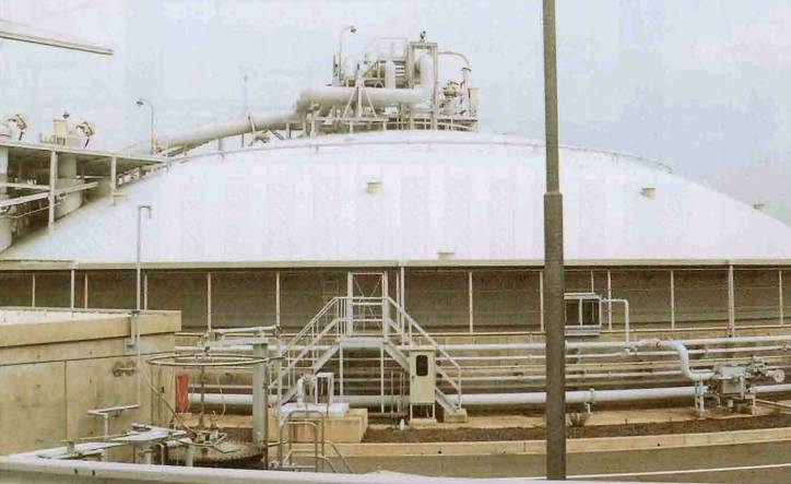
All tanks built as in-pit or semi-buried have been, up to now, of the double integrity type.
Different types of containment systems
a) Single Containment – These tanks were developed from the original, traditional, oil tanks. They were the first refrigerated tanks to be built for LPG as well as for LNG. The tanks consist of:
- A cylindrical metallic wall with a vertical axis built of suitable material designed to withstand the hydrostatic load of the stored cargo at its minimum temperature and at the maximum storage pressure.
- A flat metallic bottom.
- A self-supporting metallic spherical dome.
- Insulation made of polyurethane foam with vapour barrier located outside the cylindrical wall and inside the dome. The insulation underneath the flat bottom is usually glass foam.
In early tanks, the insulation was left exposed to atmospheric elements and the side wall was generally penetrated by an outlet pipe. Later, an outer envelope, made of thinner carbon steel, was fitted to protect the insulation, frequently consisting of perlite in bulk. When a suspended ceiling is used, the vapour from the stored cargo is contained by the outer wall. However, this outer wall is not designed to contain the liquid cargo. In-tank pumps with piping exiting through the tank roof were installed to maintain the tank wall integrity.
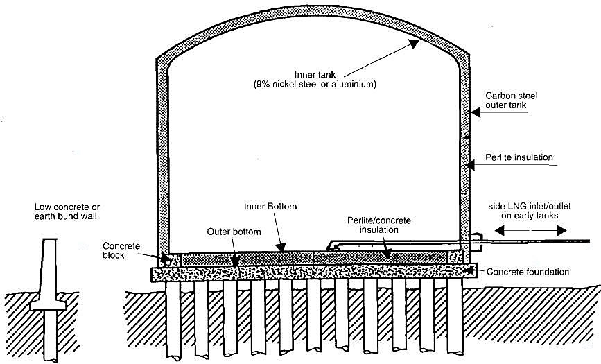
This type of tank presents minimal protection against external hazards such as fire, impact, etc. In case of leak or failure, the stored product is released to atmosphere and a low bund wall would be erected to prevent uncontrolled liquid spillage.
This type of tank has been widely used for LPG, ethylene and LNG. It is still popular in the United States.
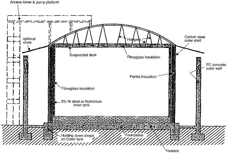
b) Double Containment – A double containment tank consists of:
- The same inner tank as the single containment design but with a tight roof.
- Insulation around the inner tank, either polyurethane foam with a vapour barrier or perlite in bulk enclosed in a carbon steel outer shell.
- An outer tank designed to contain any liquid in case of failure of the inner tank, but not designed to contain the vapour. The outer tank must be no further than 6 meters from the inner tank.
- A weather cover may be provided between tank roof and outer wall and a return water pump must be provided if a deluge system is fitted.
- The inner tank may be 9 % nickel steel, stainless steel membrane or aluminium. The outer tank is generally pre-stressed concrete but may also be 9 % nickel steel.
- Submerged pumps are provided in-tank with discharge piping through the tank roof.
- The tank base will be in direct contact with the ground, so a base heating system is required.
A few of these tanks have been used for LNG application. They are very similar to the single containment type, except for the added security of being able to contain the cargo liquid within the second containment in case of failure of the first containment. In such a case, however, the vapour is left to escape to the outside.
c) Full Containment – Tanks known as «Full Containment» or «Double Integrity» are made up of two tanks both designed to contain the stored product fully. In normal operation the product is contained in the inner tank, made of material adapted to the minimum temperature of the stored product and similar to the single wall tank. The outer container is a pre-stressed concrete tank designed to contain the stored product fully in case of failure of the inner tank. The outer tank can also be made of low temperature steel. The insulation material, placed between the two tanks can be either polyurethane foam or perlite in bulk on the vertical wall and glass foam on the bottom.
All piping and instrumentation are directed through the tank roof and a base heating system is required.
This type of tank has been in general use in recent years. It provides good protection against deterioration due to atmospheric causes, external damage by fire or impact and failure of the inner tank. It can be used above-ground, semi-buried or in-ground.
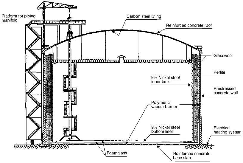
d) Membrane Tanks – The membrane tanks described higher «In-Ground tanks» are of the double integrity or full containment type. All in-ground tanks are membrane tanks, but membrane tanks can also be installed above-ground or semi-buried, when the outer shell of the tank is made in pre-stressed concrete. They are quite expensive to build and are used mainly for LNG. A simpler version has been put forward for products having a minimum storage temperature of -55 °C, such as:
- butane;
- propane;
- butadiene;
- or propylene.
The principle is the same as for the membrane type but the expensive membrane is replaced by a liquid and gastight cryogenic liner called Triplex, bonded to the insulation. Triplex is an aluminium foil held between two layers of glass cloth. This type of construction is obviously cheaper than the conventional membrane.
Standard for low temperature cylindrical vertical storage tanks
There are two main internationally recognised standards for low temperature vertical storage tanks, API 620 (appendix Q) and BS 7777. A European Standard is in the process of being formulated.
i) American Petroleum Institute API 620 – This Standard did not originally address low temperature tanks. Two appendices have been added, giving recommendations for these tanks. Appendix R covers tanks for products with a minimum temperature of -50 °C and appendix Q, products with a minimum temperature of -196 °C. The Standard does not specify special requirements for double or full containment tanks.
ii) British Standard BS 7777 – This Standard, published in 1993, was specifically developed for low temperature storage. It has superseded BS 5387. BS 7777 is the only standard to identify Single, Double and Full containment systems. Due to the difference in the type of hydraulic test applied, the thickness of the steel plates required by the BS for tanks containing low density products, such as LNG, is greater than that required by the API Standard. Due to the limitation in welding technology for 9 % nickel steel, the BS does not allow the construction of tanks above a certain size in this material.
Materials used for low temperature storage tanks
The material of construction for refrigerated tanks depends on the storage temperature. Carbon steels, in some cases nickel alloy steels or even composite materials, are used for LPG and chemical gases where the minimum temperature remains above -55 °C. For products such as ethylene or LNG with much lower temperatures, alternative materials, 9 % nickel steel, austenitic stainless steel, Invar or aluminium alloy must be used.
An increasing concern for safety has resulted in the more general use of double containment tanks or even double integrity systems for liquefied gas. This has developed the use of prestressed concrete which is now very much in favour, especially for LNG tanks.
The foundations of Transportation of the Petroleum Gas and Amonia Cargoes on the Fully-Refrigerated LPG Shipsrefrigerated tanks, particularly those built for holding LNG, require specialised attention. The tank foundations must be carefully designed to avoid possible settlement and a reliable heating system is necessary to prevent the ground freezing, leading to frost heave conditions.
Protection of the insulation against ingress of moisture was a concern with the earlier tanks but with the generalisation of double containment, this problem is now resolved.
Evolution of the size of shore storage tanks
The capacity of the first tanks built in the 1940’s was in the order of 2 000 m3 and this gradually increased to 5 000 m3. These tanks were single containment, spherical or horizontal cylindrical. Those for LNG were used for peak-shaving storage.
The beginning of the 1960’s saw the start of the vertical cylindrical tanks for LNG and LPG. Capacities were still below 10 000 m3. These tanks were single containment, built in aluminium/carbon steel with bottom outlet and a low bund wall.
Size increased to 45 000 m3 at the beginning of the 1970’s and to 60 000 m3 in the mid 1970’s. The bottom outlet disappeared and double containment, full containment and under-ground tanks were introduced.
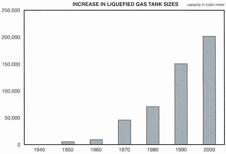
Size continued to increase and the first under-ground membrane tank, with a capacity of 200 000 m3, was commissioned in 1998.
Some possible incidents in liquefied gas shore storage tanks
Rollover
The expression «rollover» was first used to describe strange happenings observed in some lakes where, at certain times of the year, the water suddenly becomes disturbed and mud and debris from the bottom suddenly appear on the surface. This is caused by changes in the water density due to variations in the atmospheric temperature.
Liquefied gas stored in a tank at almost atmospheric pressure and low boiling temperature gains heat from outside through the imperfect insulation and this causes the product to boil off. Usually the product located at the top of the tank boils off faster than the product at the bottom and this can eventually create layers of liquid with different relative densities. In LPG tanks, the boil-off gas is reliquefied and returned into the tank, creating a certain movement in the liquid which is sufficient to ensure a good mix. In LNG tanks, however, the boil-off is used outside the tank. Under normal conditions, currents circulate from tank bottom to tank top and the density of the product inside remains homogeneous; however, this is not always sufficient to maintain a good balance. If the tank contains two or more layers of LNG of differing densities, the interface between them prevents the convection currents circulating and the boil-off stops in the lower part of the tank, which only aggravates the situation. The difference in density between top and bottom continues to increase and there is a serious risk that, at some time, the position of the two liquids will reverse suddenly, resulting in a spontaneous rapid mixing of the layers, accompanied by a violent vapour generation. The result of this phenomenon in a large tank can be quite dramatic, with a sudden rise in pressure inside the tank and the release of a large amount of vapour through the venting system. If the venting system is not able to cope with the surge of vapour, it is possible for the tank to incur damage.
Rollover is a particular risk in peak-shaving plants, where liquid is stored for long periods of time. Import terminals may also face this problem when two products from different suppliers are mixed into one tank.
Read also: Global gas market and history of LNG/LPG consumption
Rollover is preventable by good tank management. Tank content must be monitored for temperature gradient, density and boil-off rate. At the first sign of abnormality, the contents of the tank should be circulated to stop the problem developing further.
Fire hazard
The main hazard in a shore storage plant is fire. Fire can result from a leaking product, liquid or vapour, if it is ignited on the site; it can be caused by a mechanical incident or human error; or it can occur on a neighbouring industrial site. Fire can damage the other tanks by impingement, reducing the mechanical property of the tank material or by radiation, increasing the internal pressure, or a combination of the two. This is why in-ground or mounded tanks are more able to resist a fire without damage. It is also the reason all above-ground tanks should be protected by a deluge system.
A few terminal accidents have resulted in a lot of damage, for example in Mexico City and in Feysin, France. In these cases, the fire, once started, created a chain reaction, damaging the other tanks one after another, with very harmful effects. In Mexico, a number of pressurised horizontal cylindrical tanks were damaged and acted like missiles being projected several hundred metres. This is one of the reasons why those tanks must now be mounded. Pressurised spherical tanks were subjected to the very frightening BLEVE effect which will be described later. Fortunately, such accidents are rare but these resulted in many fatalities, not only in the plant but also among the surrounding population.
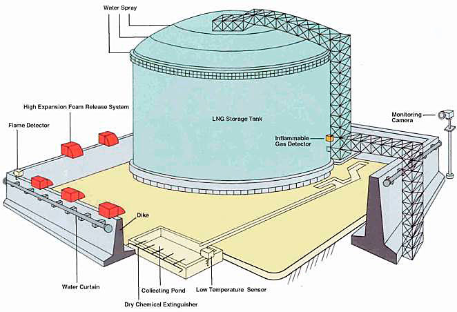
Leak prevention, fire prevention and fire protection are essential elements of storage terminal safety which must be scrupulously evaluated and maintained. Contingency plans must be ready in case of emergency and terminal personnel need to be thoroughly trained and fully familiar with the implementation of these plans.
Boiling Liquid Expanding Vapor Explosion (BLEVE)
If a pressurised tank is exposed to fire radiation without any protection, the pressure inside can rise well above the level for which the tank was designed and, at the same time, flame impingement can diminish the mechanical resistance of the tank envelope. In such a case, there is a possibility of the tank envelope tearing open and releasing its contents in the middle of the existing fire, with disastrous consequences.
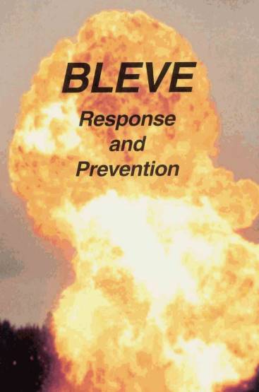
This is a very frightening phenomenon and it has spectacular results. Unfortunately, when it happens in the middle of a real fire, it also has very damaging effects.
