The imperative to mitigate the impact of liquid spill and vapour emission incidents in maritime and terminal environments necessitates a comprehensive understanding of effective response strategies. Among these, the technique of Controlled Dispersion through the strategic application of water spray stands out as a crucial method for minimizing potential hazards. This paper delves into the principles and practical applications of utilizing water spray systems to manage and disperse such incidents across various critical locations, including ships, ship-shore interfaces, and terminal facilities.
- Objective
- Short Summary
- Application on Ships, at the Ship/Shore Interface and in Terminals
- Preamble
- The Dispersion Behaviour of Liquid Spills and Vapour Emissions
- Potential Emission Incidents Considered on ships and in Terminals
- Ship Emission Incidents
- Ship emission incidents alongside the loading or discharge terminal
- Emission incidents on loading/discharge jetty during ship/shore cargo transfer
- Liquid or vapour emission incidents within the terminal process and storage area or from nearby facilities
- Review of Some Design and Operational Techniques for the Control of Liquid Spill and Vapour Emission Incidents
- Equipment for Controlled Dispersion by Water Spray – Performance Considerations
- Description of Liquid Spills/Vapour Emissions which may be Safely Controlled/Dispersed by Water Spray Techniques
- Description of Liquid Spills/Vapour Emissions which Require Caution in the use of Water sprays Prior to Ignition
- Protection of Personnel from Potential Fire, Explosion or Toxic Hazards During Controlled Dispersion Operations
- Aspects for Further Study
- A brief description of the air entrainment performance of fire water monitors and water nozzles used on ships and in terminals with some simple estimation methods
- Gas Carrier Fire Water Systems
- A brief description of the air entrainment performance of fire water monitors and water nozzles used on ships and in terminals with some simple estimation methods
- A brief description of the performance of full-scale water spray barriers when dispersing accidental spills of heavy gases with some simple estimation methods
By examining the dispersion behavior of different substances and reviewing existing design and operational techniques, this study aims to provide insights into the performance considerations of water spray equipment and delineate scenarios where Controlled Dispersion can be safely and effectively employed. Furthermore, it addresses crucial aspects concerning personnel protection during these operations and identifies areas warranting further investigation to optimize the implementation of Controlled Dispersion strategies.
Objective
To assist Members in a review of emergency response equipment, instructions and training for the controlled dispersion of accidental liquid spill and vapour emission incidents by water spray.
Short Summary
The best design and operational technique is to prevent liquid spill and vapour emission incidents.
If emissions do occur the first requirement is to detect the emission and to alert operators as quickly as practicable. The second requirement is to minimise the emission by isolation of the source.
Whilst this Information Paper addresses the use of water spray for the controlled dispersion of liquid spill and vapour emission incidents, some other design and operational techniques are described in Section “Review of some design and operational techniques for the control of liquid spill and vapour emission incidents”.
Existing fire-fighting water monitors and hand-held water spray nozzles can often provide a rapid and flexible means of controlled dispersion:
- by controlling the direction of the dispersion;
- by diluting the gas with air entrained by the water spray;
- by heating the relatively cold gas to increase its buoyancy;
- by absorption of some toxic gases which are soluble in water, e. g., ammonia and chlorine.
Fixed water spray curtains may be installed around potential sources of vapour emission which achieve the same purposes.
Water spray curtains may also be used in the event of fire to mitigate the effects of thermal radiation so as to protect facilities and personnel adjacent to the fire. However, vertical-upward spray protection facilities at the Ship/Shore Interface in Gas tradingship/shore interface should not be activated prior to ignition when there is a danger that they may entrain a heavy gas cloud in a manner which may increase the potential hazard.
Portable gas detectors should always be used to check the actual gas concentration and to check on the effectiveness of the water spray containment dispersal.
Application on Ships, at the Ship/Shore Interface and in Terminals
Management responsible for design, operation, maintenance, and training will wish to review this document in consideration of its application to their areas of responsibility. The emergency response to a gas leak must be pre-planned in view of the speed with which a gas leak may develop into a potentially dangerous incident. Possible sources of liquid spillage and vapor emissions should be identified, and the emergency response action pre-planned with due consideration to the guidance given in this document. The emergency response protection of known sources of ignition should similarly be pre-planned.
Personnel who may be involved in such incidents should be instructed and exercised in these emergency response procedures, in the use of protective clothing and breathing apparatus, and in the use of portable flammable and toxic gas detection equipment. Such emergency response at the ship/shore interface should be discussed and agreed in writing prior to every Comprehensive Overview of LNG and LPG Cargo Hoses in STS Operationscargo transfer in accordance with the Safety Check List Guidelines (Reference 1, Guidelines Cl(c) and).
Preamble
Spillages that have occasionally occurred aboard a ship or during loading/discharge at a marine terminal have generally resulted in dispersion without ignition. The basic science of water curtains and water-assisted directional control and dilution of gas spillage may now be sufficiently well researched to enable a study of its application to safer ship and jetty emergency response, i. e., when to use water sprays and when not to use water sprays.
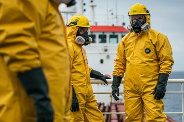
Source: Unsplash.com
In addition to the avoidance of ignition, water curtains and sprays have a further application in the control of a toxic ammonia gas spill and to make small ammonia and LNG spills buoyant. Water sprays are also widely used as radiation barriers (Reference 2). However, this document is confined to the application of water sprays for the controlled dispersion of liquid spill and vapor emission incidents.
Forty-five representatives of Members and invited guests attended a Workshop at the Fire Service College, Moreton-in-Marsh, UK, on 7th and 8th May 1986 to witness some practical demonstrations of the controlled dispersal of carbon dioxide spills using fire water monitors, hose nozzles, and flat fan sprays.
Photographs of some of these demonstrations are shown in Figures 1 to 6 (Reference 2).
Presentations were made by three invited speakers, the subjects being:
- Water Spray Technology (Reference 3);
- Case History of the Successful Control and Dispersal of a 7 tonne propane release in a refinery (Reference 4);
- Personal experience of the Manager, Fire, Safety & Security Services at a petrochemical plant in the development of the flat fan spray and the use of water sprays for the control and dispersal of gas liquid spill and vapour emission incidents.
Expert contributions were made by many of the persons present including presentations on References 2 and 5.
A small Working Group of Members and invited experts who attended this Workshop were deputed by the Workshop participants to prepare a document to meet the objective described in Section “Objective” above. Their contributions are gratefully acknowledged.
The Dispersion Behaviour of Liquid Spills and Vapour Emissions
The behavior of liquid spills and vapor emissions is now described. Ammonia and natural gas at ambient temperatures are both lighter than air and will rise and disperse naturally, moving in the direction of the wind.
However, spills of liquefied natural gas and ammonia or emissions from pipelines under pressure will result in cooling of the gas to a temperature below the ambient air temperature, and this usually results in gas and liquid spills generating gas clouds which are heavier than air and which naturally drain over the side of ships and hug the water or the ground.
Read also: Optimizing Local Content: From Definition to Delivery
The nature of the emission and vaporization processes determines the dispersion characteristics of the gas cloud. High velocity vertical emissions of gas will tend to mix with air and rapidly disperse to below flammability. In contrast, low velocity gas emissions or liquid spills form a plume in which mixing with the surrounding air is comparatively slow. Such plumes drift downwind and may be flammable for considerable distances from the point of spill. Reference 6 is a useful introduction to the subject, and papers on the current state of the art of gas dispersion prediction are presented at many chemical safety and loss prevention conferences.
Reference 9 reviews some methods which can be used to calculate release rates, liquid, vapor, or 2-phase, from installations following the loss of containment incidents. The liquid and vapor pumping capacities, pressure relief valve discharge capacities, and pipeline inventories will be known from the operation manuals.
The extent of a flammable or toxic gas cloud may only be determined with certainty by constant checking with gas detection equipment. However, Reference 7 stated, “For typical humidities at Maplin (60-90 %), for liquid spills on seawater, the propane vapor clouds cease to be visible at dispersion distances well short of the LFL point but beyond the upper flammable limit (UFL) point. LNG clouds, on the other hand, remain visible beyond the LFL point, the calculated humidity for which the visible edge of the white cloud and the LFL point coincide being about 50 %.” Reference 7 stated that the ambient humidity and the type of Safety Liquefied Gas of Marine Transportationliquefied gas spilled were important variables. However, LPG vapors may not always be visible, especially in cold and dry weather conditions over land or when emitted as warm vapors.
Source: Pixabay.com
Reference 8 and Figures 7 and 8 (large-scale ammonia spill tests) describe the release of ambient temperature liquefied ammonia in a horizontal direction 0,8 m above ground level and downwind. At 800 m downwind of the spill point, the gas cloud was still visible and only 6 m high and about 400 m in width.
The ammonia concentration was 2 % by volume, and the temperature of the gas cloud was 9 °C below ambient – thus the cloud was still heavier than air. Gas sensors 8,5 m above ground showed very little, if any, gas. The spillage of LNG on water shows a similar effect (Reference 7). The spillage of ammonia on water would however result in considerable heat of mixing and more rapid upward dispersion of the toxic ammonia gas cloud than for spills over dry land.
Another behavior of interest is clearly shown in the ammonia spill reference where a liquid pool was established immediately downwind of the spill point.
The soil temperature was 31 °C before the spill commenced, but the pool developed temperatures down to -63 °C, whereas the boiling point temperature of ammonia at atmospheric pressure is -33 °C. This is due to the liquid ammonia continuously evaporating in attempting to develop an atmosphere of ammonia in equilibrium with the liquid, which it cannot do, so that the liquid self-refrigerates itself to a substantially lower temperature. Personnel should therefore always wear protective clothing to avoid the cold burns which rapidly evaporating liquefied gas will inflict due to this behavior.
Whilst LNG vapor clouds tend to be low lying and distinct over open ground or the open sea, in the presence of a ship the vapor may be carried up around the superstructure and be more diffuse. Even for spills on the water adjacent to a ship, the vapor may be drawn up into the recirculation zone created by wind blowing over the ship. Wind tunnel modeling described in Reference 5 indicated that flammable vapor could exist at one of the engine room air intakes over a wide range of wind directions. If the spill was shut down within about 30 seconds, the mean vapor concentration within the engine room was always below the lower flammable limit. (See Figures 9 and 10).
The natural dispersion of a liquefied gas spill or a vapor emission on a ship, where there is a natural drainage off the cargo deck and down onto the surface of the water, is in distinct contrast to a similar incident at a terminal, where often the only safe place for the spillage is by assisted dispersion vertically upwards.
Potential Emission Incidents Considered on ships and in Terminals
Ship Emission Incidents
Pipeline liquid leakages, for example from liquid loading/discharge lines during cool-down or prior to draining after loading/discharge operations, from cargo heaters and vaporizers or from condensate return pipework in reliquefaction room or on deck; liquid release from a liquid full condenser or from thermal pressure relief valves in liquid piping which results in liquid accumulation in relief pipework and mast riser.
Vapour relief through tank pressure relief valve or manual venting valve when gas-freeing or changing cargoes.
Ship emission incidents alongside the loading or discharge terminal
Liquid spill as in vapor relief through tank pressure relief valve. Liquid spill in Preparation and Execution Cargo Operations LNG and LPGcargo transfer pipework or at ship/shore presentation flange connection or shipboard leg of hose or hard arm. Vapor emission as in.
Emission incidents on loading/discharge jetty during ship/shore cargo transfer
Liquid leakage from shore side leg of loading arm or hose, liquid leakage in jetty pipework, drain tank or surge relief tank connections. Vapour emissions from vapour return pipework and ship/shore connection.
Liquid or vapour emission incidents within the terminal process and storage area or from nearby facilities
This point addresses unplanned releases of liquids or vapours, originating either from within the terminal’s processing and storage areas or from adjacent facilities. These emission incidents represent unintentional escapes of substances in their liquid or gaseous state into the environment, requiring consideration of both on-site and nearby potential sources for safety and Environmental management of ships during transportation of LNG/LPG gasesenvironmental management.
Review of Some Design and Operational Techniques for the Control of Liquid Spill and Vapour Emission Incidents
The best design and operational techniques will minimise the risk of liquid spill and vapour emission incidents. However, if emissions do occur, the first requirement is to detect the emission and to alert operators as quickly as practicable. The second requirement is to minimise the emission by isolation of the source.
Whilst this report addresses the use of water spray for the controlled dispersion of liquid spill and vapour emission incidents, there are many other design and operational techniques with the same objective, for example:
Ship
Provision for the emergency shut-down of pumps, compressors and valves, the provision of drip trays, fixed water sprays to protect hull structure in way of ship/shore connections, maneuvering of the ship to carry vapour emissions away from the accommodation and engine room air intakes, operation of closing devices fitted to all air intakes into accommodation spaces, service spaces and control stations etc.
Terminal
Provision for the emergency shut-down of pumps, compressors and valves, separation distances between berths, the provision of drainage from underneath onshore pressure storage to a safe area, the use of insulation on the floor and walls of tank bunds and bunded safe area to reduce the rate of vaporisation of liquid spills, the use of fire fighting or special blanket foams to reduce the rate of vapour boil-off before ignition, the use of vapour fences and separation distances in terminal plant layout and a cordon sanitaire to keep the public outside the estimated worst credible incident Electrical Safety in LNG Carrier Hazardous Areashazard area.
Both ship and terminal have gas detectors in order to give an early warning that gas leakage has occurred; however, gas leakage may pass between fixed gas detection points unrecorded.
Protection of ignition sources
The protection of ignition sources by water spray is described in Sections “Equipment for Controlled Dispersion by Water Spray – Performance Considerations” and “Description of Liquid Spills/Vapour Emissions which may be Safely Controlled/Dispersed by Water Spray Techniques”. Consideration must also be given to shutting down plant and power supplies which may be a source of ignition in the possible path of the flammable gas cloud.
Operating diesel engines are known to have been the ignition source of several flammable gas clouds. Reference 10 “Recommendations for the Protection of Diesel Engines operating in Hazardous Areas” or equivalent references should be consulted before permitting diesel engined equipment to operate in potentially hazardous areas; strict control should be imposed on the operation of self propelled road vehicles and harbour service craft for this reason.
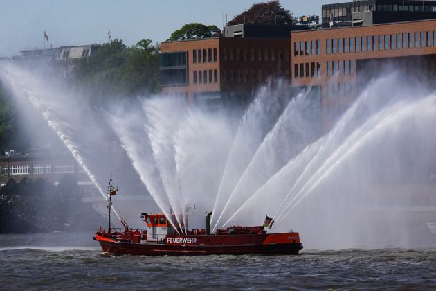
Source: Pixabay.com
Adequate maintenance of the protection features of diesel engines for operation in hazardous areas should be strictly enforced. Ships diesel driven emergency fire pumps should probably not be started if a gas cloud is anticipated in the vicinity. Pleasure craft and road vehicles should be kept away and outside a safe distance at all times. The discharge of CO2 from a fire extinguisher into the air intake of a diesel engine will stop it. However, diesel engines that are permanently installed in hazardous areas must be protected so as not to provide a means of gas cloud ignition. The protection should include an automatic shut-down device on the air intake system.
Equipment for Controlled Dispersion by Water Spray – Performance Considerations
References 2, 3, 11, 12 and 13 refer to laboratory and to full scale testing of water spray equipment and section “A brief description of the air entrainment performance of fire water monitors and water nozzles used on ships and in terminals with some simple estimation methods” below is an assessment of the gas entrainment performance of firefighting water monitors and hose end nozzles used on ships and in terminals with some simple estimation methods.
Water sprays act as a gas pump in the following way.
- The surrounding gas is entrained by the liquid droplets emerging from a water spray nozzle;
- the quantity entrained is dependent on the free access to the base of the water nozzle, on the size and distribution of the water droplets and on their velocity;
- these characteristics of the water droplets and their velocity are governed by the design and arrangement of the nozzles and the pressure of the water;
- the interference between adjacent spray patterns, the effect of falling water droplets from upward sprays and the wind also have an important effect on the gas pumping performance. For gases which are lighter than air at ambient temperatures, for example natural gas and ammonia, water sprays will also warm the cold dense air-gas cloud to assist upward dispersion.
It is difficult to measure the above effects separately and therefore performance is determined by measurement of gas concentrations, first without the water sprays and second with the water sprays operating. The tests reported in Reference 2 showed that a water spray barrier using 200 litres/minute per metre length resulted in a 50 % reduction in gas concentration from a pool of evaporating LNG.
The following table illustrates the gas entrainment performance of a standard firefighting water monitor and some proprietary spray nozzles when tested, full scale, as described in Reference 3 for comparison with a single, much smaller, nozzle tested in the laboratory described in Reference 11:
| Illustration of the gas entrainment efficiency of a standard fire water monitor and some proprietary spray nozzles under testing | ||||
|---|---|---|---|---|
| Type of Nozzle | Water Pressure bar, g | Water Flow m3/Hr | Air Flow m3/Hr | Volume of gas entrained per m3 water flow |
| Monitor | 7 | 190 | 1 140 000 | 6 000 |
| Shell 180° Fan Spray | 10 | 59 | 94 800 | 1 600 |
| 25 mm 25° Fan Spray | 10 | 22 | 50 800 | 2 300 |
| Rockwood T-4 6,35 mm spray nozzle (Ref 11) | 2,8 | 2,6 | 37 800 | 14 500 |
The downwind concentrations resulting from “demonstration” ammonia releases of 2 kg/second have been reduced to 200 ppm from 15 000 ppm through use of six hoses delivering spray at rates of 20 m3/hour each (Reference 20).
This reduction in concentration is far greater than the three-fold reduction which would have been provided by entrained-air dilution alone, attesting to the effectiveness of absorption by the water sprays. Similar absorption by water sprays has been reported for hydrogen chloride, hydrogen fluoride, chlorine and ethylene oxide. Water spray techniques are suitable for:
- Dilution of continuous gas leaks to below their lower flammable limit (LFL).
- Protecting ignition sources by controlling the direction of flow of the flammable gas clouds.
- Diverting flammable clouds from sensitive areas, such as confined spaces where a detonation may occur on ignition, or from office or control room accommodation.
- Assisting the diversion of toxic gas clouds from areas occupied by people.
- Providing heat to a cold gas (e. g., LNG) cloud to enhance buoyant dispersion.
- Absorbing some gases (e. g., ammonia) into solution in the water.
Caution should be adopted if using water sprays for diluting large flammable gas leaks or instantaneous releases which require a corresponding scale and arrangement of water sprays. The spray may not dilute to below the LFL but only increase the volume of the pre-mixed cloud.
The performance of water sprays in diluting and controlling direction of gas clouds reduces with increasing wind velocity. Water sprays are not suitable to act as an impenetrable barrier; they only dilute gas clouds passing through them by mixing with air. Also they will not contain a high velocity jet leakage if placed too close to the point of leakage.
It will be interesting: Linked ESD Systems at Both LNG and LPG Terminals
Water spray may not prevent ignition; indeed the turbulence and mixing caused by water spray may increase the flame speed on ignition, but water spray will assist the protection of people, structures and equipment from radiation heat damage should ignition occur. (References 14 and 15). Portable gas detectors should always be used to check on the effectiveness of water spray containment or dispersal.
Consideration must also be given to the large quantities of water released by the water sprays which will fill drainage ditches and may cause accumulations of heavier hydrocarbons to float out and cause additional hazards.
Description of Liquid Spills/Vapour Emissions which may be Safely Controlled/Dispersed by Water Spray Techniques
An examination of the fire main capacity and pressure and available jet/spray equipment will determine the size of liquid spill/vapor emission incidents which may be safely directed and/or diluted to below half the LFL. This may include leakages in loading arm swivel joints, pipeline flange connections, cargo pump shaft seals and, possibly, the vapor vented from a ship’s mast riser due to the operation of a cargo tank pressure relief valve.
Gas which is vented through the mast riser from a tank pressure relief valve or by a manual control valve may be similarly directed and/or diluted to below the LFL if sufficient water capacity and pressure is available for this purpose; it is important that the jet spray does not enter the mast riser vent where it may freeze due to the low temperature of the vented gas and thus cause a restriction in the vent outlet. There have been a few incidents in which relief valves have remained open for a considerable period resulting in plant or port shut down; the satisfactory development of a viable water spray controlled dispersion technique may prevent a costly shut down and reduce the Hazards and Risks in Usage of Land Transport in Oil and Gas Industrypotential hazard from such incidents in the future.
Source: Pixabay.com
Such action should be pre-planned as the quantity of gas spilled or emitted will accumulate until water dispersion is activated (unless the wind conditions are favorable to its safe dispersion); this is particularly necessary where the jetty fire water monitors may be used to direct a loading arm or ship board accidental emission away from the jetty and over the side of the ship away from the ship’s accommodation and engine room ventilation intakes.
Once a decision to control the gas cloud by water spray has been taken, the maximum quantity of water spray available should be deployed as quickly as possible.
An alternative important consideration is to prevent a flammable gas cloud from reaching a potential source of ignition; this may be achieved by redirecting the gas cloud to one side of the ignition source by water spray techniques.
Small pipeline liquid leakages may be vaporised with water from one hose and dispersed to below the LFL with water spray from another hose. It is normal practice to protect the steel deck structure of a ship by sluicing liquid spills over side and additional water jets would assist its dispersal down and away from the ship side.
Portable gas detectors must always be used to check on the gas concentrations actually present and on the effectiveness of the water sprays in use to contain the gas cloud.
Description of Liquid Spills/Vapour Emissions which Require Caution in the use of Water sprays Prior to Ignition
Consideration of the available capacity of water spray will indicate the size of liquid (and perhaps vapour) spills which may not be diluted to below the LFL and which therefore will increase the volume of gas diluted with air into the flammable range in the immediate vicinity. Consideration may still be given to the protection of personnel or a potential ignition source by deflection of the edge of the gas cloud around the vulnerable area – for example, ship’s accommodation, terminal electric substations, process control rooms, etc.
Prevention of Environmental Pollution by Tankers in the Event of Chemical SpillsLiquefied gas spills or leakages on the deck of a gas carrier or from the ship/shore connections will drain naturally off the deck or jetty onto the surface of the water. Some jetties are equipped with fixed vertical-upward water spray barriers as a protection from radiated heat from an adjacent fire.
Such fire protection equipment should not be activated prior to ignition when there is a danger that it may entrain a heavy gas cloud in a manner which may increase the potential hazard. Before these water spray barriers are used to assist the dispersion of a vapour cloud, it is essential that the shore advise the ship and that the ship’s ventilation intake system is shut down and that the intake fire dampers are closed.
Protection of Personnel from Potential Fire, Explosion or Toxic Hazards During Controlled Dispersion Operations
Personnel conducting the controlled dispersion of flammable or toxic gas clouds and personnel checking on the gas concentration actually present should wear full protective clothing to protect them in the event of ignition. They should also wear self-contained air-breathing apparatus. The air-breathing apparatus should be of the positive pressure type to minimise the ingress of toxic gases through the face/mask seal. The communications equipment used must be intrinsically safe, and lighting and torches in use must be flameproof or safe for use in flammable atmospheres.
Personnel should always be directed to respond upwind of such clouds. However, it is recognised that this is not always possible and may be required to enter a gas cloud to locate and isolate the source of leakage. Should this be necessary, lifelines should be used and personnel kept protected by water sprays. A rescue team, equipped with protective clothing and breathing apparatus, should be ready for immediate intervention.
Source: AI generated image
The best refuge from potential fire, explosion, or toxic hazard is within the ship’s accommodation or inside a designated pressurised safe building where there is protection from radiated heat or explosion on ignition, and from toxic gas. Occupied buildings which are situated in the vicinity of toxic or flammable gas operations should be protected by appropriate gas detection systems which are interconnected to an alarm system audible throughout the buildings. In the event of gas penetration at the perimeter of buildings, an immediate evacuation should be effected.
Consideration should always be given to wind direction in deciding the safest escape route (which is normally across the wind) and the safest under-cover protection.
Aspects for Further Study
The air-moving performance of ship and terminal fire protection and water spray equipment needs to be established in order that decisions on their use, or their non-use, can be made on a more firm basis. Quantitative information on the rate of absorption of toxic gas (e. g., ammonia) into water spray is desirable.
A brief description of the air entrainment performance of fire water monitors and water nozzles used on ships and in terminals with some simple estimation methods
Gas Carrier Fire Water Systems
A1.1
Every gas carrier is required to have at least two fire pumps and an emergency pump. Each pump is to be capable of supplying at least two jets of water and to have a minimum capacity of 25 m3/hour. The total capacity of the fire pumps need not exceed 180 m3/hour. The minimum pressure at fire hydrants is to be at least 5 barg. (This relatively modest fire pump capacity originates from the need to pump fire water out of a ship to prevent the ship becoming unstable). An International ship/shore fire connection is provided. Hydrants are to be fitted and hoses not exceeding 33 m provided such that at least two jets of water, not emanating from the same hydrant, may reach any part of the cargo deck. All water nozzles are to be of the dual-purpose (e. g., spray or jet) type and 12 mm, 16 mm or 19 mm standard sizes are normally used.
A1.2
In addition, a water spray protection system of at least 10 litre/m2 per minute for horizontal surfaces and 4 litre/m2 per minute for vertical surfaces is to be provided to cover:
- exposed cargo tank domes and any exposed parts of cargo tanks;
- exposed on-deck storage vessels for flammable or toxic products;
- cargo liquid and vapour discharge and loading manifolds and the area of their control valves and any other areas where essential control valves are situated and which should be at least equal to the area of the drip trays provided; and
- boundaries of superstructures and deckhouses normally manned, cargo compressor rooms, cargo pump rooms, store-rooms containing high fire risk items and cargo control rooms, all facing the cargo area. Boundaries of unmanned forecastle structures not containing high fire risk items or equipment do not require water spray protection.
The capacity of the water spray pumps required may be added to the capacity of the main fire pumps (which may then be in excess of the 180 m3/hour maximum required under A.1.1). This typically adds 250 to 500 m3/hour water capacity to the ship’s regulation fire pump capacity.
A brief description of the air entrainment performance of fire water monitors and water nozzles used on ships and in terminals with some simple estimation methods
A2.1
As described in Section 8, the gas entrainment performance of two 1 800 litre per minute fire service monitors with a water pressure of 7 bar g was measured to be 6 000 m3 gas per m3 water flow (Reference 16), when tested as described in Reference 3 with the monitors placed 20 m apart, angled upwards at 45° and pointed towards each other across the wind direction. This is the method of use adopted by some Fire and Emergency Services when dispersing a heavy gas cloud vertically upwards to prevent the cloud drifting with the wind into adjacent facilities. The heavy gas is drawn into the base of the water jet and accelerated upwards with the water droplets which have their maximum vertical velocity at this point of over 20 m/second at 7 bar g water pressure.
A2.2
If a single fire service water monitor or hose is used to entrain air outside a gas emission, in order to control the direction and dilution of that gas emission, Reference 17 suggests that an air velocity of 6 metres/second is required at its point of contact with the gas emission to ensure adequate turbulence for mixing. Assuming an efficiency of at least 50 % of that obtained in the full-scale trials described in A2.1 above, the air entrained by the water spray when the air velocity is 6 m/s may be at least 3 000 × m3 water flow through the nozzle at a water pressure of 7 bar g. At lower water pressures the entrainment volume will be reduced, at higher water pressures the entrainment volume will be increased.
A2.3
Assuming that the air entrained lies within the boundary of the water spray, then the diameter of the spray at its point of contact with the gas emission for optimum efficiency may be quickly estimated.
For example, the pages which follow give the measured throw performance for a proprietary range of monitor nozzles. The Type N.2700 nozzle gives a water flow of 3 250 litres/minute (0,05417 m3/second) at 10 bar g water pressure which is the normal supply pressure at marine jetties.
The air entrainment performance will be about 3 000 × 0,05417 = 162,5 m3/second.
The optimum diameter of the water spray at the point of contact with the gas emission is given by:
Volume of air entrained,
or, for 6 m/s velocity,
and, for this example:
where:
- ∴ D = 5,9 metres, say 6 metres.
An examination of the Type N.2700 throw performance characteristics indicates that this monitor nozzle could be effective in this mode of operation at over 34 metres from the gas emission with the nozzle set at less than the 10° spray pattern to give 6 metres diameter at this distance. The volume of air entrained of 162,5 × 60 = 9 750 m3/minute is therefore capable of diluting a propane gas leakage of about 97 m3/minute to 1 × Lower Flammable Limit.
A2.4
The direction and dilution performance of the proprietary branch pipe nozzle may be assessed in a similar manner.
The water flow for the 19 mm nozzle at 6 bar g water pressure is 220 × P1/2 litres/minute; the air entrainment will be about:
and the optimum spray diameter at the point of contact with the gas cloud will be given by:
An inspection of the narrow 5° spray range, which will give the required diameter at maximum range, shows that this nozzle will be effective at up to 20 metres and may be expected to dilute a propane vapour leak of about 16 m³/minute to 1/2 × Lower Flammable Limit.
At a water pressure of 10 bar g the range increases to 25 metres and a gas leak of 20 m³/minute may be safely dispersed.
A2.5
Reference 18 gives estimation methods for the water flow rate of nozzles and for the pressure drop in fire hoses:
The volume of water (Qw) in litres/minute from a nozzle diameter (d) in mm at a water pressure P in barg is given by the expression:
For example, the flows through a 19 mm nozzle at 5, 7 & 10 bar g water pressure are about:
The pressure drop (p) in bar in a hose length (L) metres, internal diameter (dh) mm and a hose friction factor (f) of 0,005 is given by the expression:
For example, the pressure drops in a hose length of 33 meters, internal diameter 63 mm (2,5 inch) when passing 484, 573, and 684 liters/minute are about:
and
A brief description of the performance of full-scale water spray barriers when dispersing accidental spills of heavy gases with some simple estimation methods
A3.1
References 2, 3, and 13 describe the full-scale testing of water spray barriers when dispersing heavier-than-air gas spills. As described in Section 8, the performance characteristics are determined by a full-scale test using a heavy gas (normally CO2) and measuring the concentrations, first without the water sprays and second with the water sprays operating.
A3.2
Reference 3 describes the full-scale testing undertaken at Buxton, UK, to examine the influence of spray nozzle type, the influence of upward and downward direction of the water spray barrier, and the influence of wind speed. This Reference favors the use of the specific momentum flow rate characteristic for the design of spray barriers and gives a simple estimation method for vertical-up water spray barrier design.
The performance characteristic is defined as the Concentration Ratio (CR), or dilution ratio, in terms of gas concentrations with and without the barrier working.
Source: AI generated image
The momentum flow numbers were derived from nozzle thrust measurements for the nozzles tested which, when plotted against the manufacturers flow data, result in the relationship shown in Figure A3.1. The momentum flow number recognises that a higher initial droplet velocity for a given water pressure should result in a higher gas entrainment rate. The Momentum Flow Number is expressed in Newton-Seconds per second per bar, and the Volume Flow Number is expressed in litres per minute per square root of bar. Figure A3.1 may be used for a simple estimation of Momentum Flow Number from manufacturers flow data.
The Specific Momentum Flow Rate (M) is defined as:
In Newton-seconds per second per metre.
The effect of wind speed is introduced by plotting the square root of the Specific Momentum Flow Rate divided by wind speed (as a characteristic length scale for the behaviour of a gas jet in a crossflow) as a function of the gas Concentration Ratio. This is shown in Figure A3.2 for upward pointing water spray barriers which offers a simple estimation method for a required degree of gas dilution at a specified wind speed.
A3.3
Upward-pointing water spray barriers mounted at ground level draw a flow of heavy gas from both sides into the water spray. This heavy gas is then accelerated vertically and mixed with the air flow as high as the water spray will travel.
Read also: Marine Safety System Integration and Compliance
If it is desired to use a water spray as a barrier between a source of heavy flammable or toxic gas and a potential ignition source, it may be desirable to mount the water spray on one side of a gas-tight wall. By this means, the gas flow into the water spray will be from the one side of the wall on which the spray is mounted. However, careful consideration should also be given to the accumulation of heavy gas leakage resulting from the presence of a gas-tight wall.
Reference 19 describes heavy gas dispersion trials in which the effects of gas-tight and permeable vapor fences were measured. For example, a height of vapor fence to block a heavy gas flow at low wind velocities may be simply calculated and was found to be generally in line with prediction. The effect of a line of trees was also simulated.

- ICS et al, Ship/Shore Safety Check List Guidelines, 1982, Witherby & Co Ltd., London.
- Report on experim ents of LNG flame radiation and vapor dispersion, The Tokyo Electric Power Co Inc., June 1980.
- The use of water spraybarriers to disperse spills of heavy gases. K. Moodie, Plant/Operations Progress, Vol. 4, No. 4, 1985.
- Case history of a liquid propane release in Norsk Hydro’s Ethylene Plant Rafnes, Norway, 8th July, 1981 – The Inst, of Chemical Engineers, UK, Loss Prevention Bulletin No.043, 1981.
- British Gas Canvey LNG Terminal: The analysis of the hazards of ship-to-shore transfer – D. M. Lucas et al, Chemical Engineers L. P. Symposium, Harrogate, UK, 1983.
- Loss Prevention in the Process Industries Vol I chapter 15, Emission and Dispersion, F. P. Lees, Butterworth & Co, publishers, 1980, London, UK.
- Dispersion and combustion behaviour of gas clouds resulting from large spillages of LNG and LPG on to the sea, D. R. Blackmore et al, Institute of Marine Engineers, UK, 1982.
- Large-scale ammonia spilltests, H. C. Goldwire Jr, Lawrence Livermore National Laboratory, California, USA, CEP April, 1986.
- Discharge rate calculation methods for use in plant safety a ssessments, P. K. Ramskill, Safety and Reliability Directorate, UK, 1986.
- Recommendations for the protection of diesel engines operatingin hazardous areas, Oil Companies Materials Association, UK, 1980.
- Air entrainment into water sprays, Gunnar Heskestad et al, Factory Mutual Research, USA, 1977.
- Examination of entraine dair-flow rate data for large-scale water spray installations, J. McQuaid, 1978, Health and Safety Laboratories, UK.
- Full scale test of a water curtain in operation, K. Emblem, Chemical Engineers Loss Prevention Symposium, Cannes, France, 1986.
- Effects of water spray on unconfined flammable gas, J. W. Watts Jr, 1976, AIChE Loss Prevention Symposium, Kansas City, USA.
- Water spray to reduce vapour cloud spray, L. A. Eggleston et al, Southwest Research Institute, USA.
- Private communication to SIGTTO from H. S. E., Buxton, 1987.
- The design of water-spray barriers for chemical plants, J. McQuaid, Chemical Engineers L. P. Symposium, Heidelberg, 1977.
- Fire Technology Calculations, P. A. D. Sheen and A. Gray, Institute of Fire Engineers, UK, 1980.
- Some effects of obstructions on the dispersion of heavy gas clouds, J. McQuaid, University of Manchester Institute for Science and Technology Symposium, UK. 1986.
- Private communication to SIGTTO from R. W. Prugh, Hazard Reduction Engineering, USA, 1987.
- International Maritime Organization (IMO). (2020). International Code for the Construction and Equipment of Ships Carrying Dangerous Chemicals in Bulk (IBC Code). London: IMO Publishing.
- International Maritime Organization (IMO). (2019). Guidelines for the Safe Transport of Dangerous Cargoes and Related Activities in Port Areas. London: IMO Publishing.
- Smith, J. A., & Johnson, R. L. (2021). Cargo Tank Overfill Protection: Best Practices and Recommendations. Journal of Maritime Safety, 15(3), 45-67.
- Brown, T. E. (2022). Understanding Level Settings in Cargo Tanks: A Comprehensive Guide. Marine Engineering Review, 10(2), 112-130.
- Green, P. H., & White, S. M. (2020). Alarm and Shutdown Sequences in Maritime Operations: A Safety Perspective. Safety Science, 78, 25-34.
- International Maritime Organization (IMO). (2018). Guidelines for the Testing and Maintenance of Safety Equipment on Ships. London: IMO Publishing.
- Davis, L. R. (2021). Managing Unwanted Alarms in Maritime Systems: Strategies and Solutions. Journal of Marine Technology, 12(4), 88-99.
- Thompson, R. J. (2019). Relief Valve Venting Systems: Design and Operational Considerations. Chemical Engineering Journal, 45(1), 15-29.
- International Maritime Organization (IMO). (2021). Recommendations on the Safe Handling of Cargoes in Bulk. London: IMO Publishing.
- National Fire Protection Association (NFPA). (2020). Standard for the Installation of Sprinkler Systems (NFPA 13). Quincy, MA: NFPA.