Explore a variety of liquefied gas tanker types designed for safe and efficient transportation of gases such as LNG (Liquefied Natural Gas) and LPG (Liquefied Petroleum Gas). From fully pressurized vessels to semi-refrigerated and fully refrigerated tankers, each type is meticulously engineered to meet industry standards and ensure secure delivery of liquefied gases worldwide.
Discover the optimal tanker solution for your cargo needs, whether for short-haul or long-distance transport, with our comprehensive guide to liquefied gas tanker types.
General – the IMO CODE definitions
The evolution of liquefied gas tankers over the years has been broadly determined by the different types of product to be transported, their physical condition at the loading and discharging ports and the improvement of technology. We have seen that the first ships were designed to transport small quantities of butane and propane at ambient temperature. The maximum pressure of propane at +45 °C +45 °C is considered the maximum temperature that a cargo is likely to reach during any sea-going voyage. On pressurised ships without a refrigeration system, a network of water pipes with spray nozzles is arranged over the tank tops to cool the tanks if the temperature is likely to rise above this limit.x is 16 bar gauge and this decided the maximum pressure for which the tanks had to be designed. Very soon, ammonia was added to the list of products to be transported and the maximum pressure to be considered for the design of the cargo tanks was increased to 18 bar gauge, as this is the maximum pressure of ammonia at +45 °C +45 °C is considered the maximum temperature that a cargo is likely to reach during any sea-going voyage. On pressurised ships without a refrigeration system, a network of water pipes with spray nozzles is arranged over the tank tops to cool the tanks if the temperature is likely to rise above this limit.x. The technology and materials available for the construction of the tanks at that time only allowed fairly small units. The weight of the tanks was a further limitation on ship size.
Demand for the transport of larger volumes of cargo and development of improved reliquefaction and metallurgical technology allowed the construction of tanks with lower maximum design pressures and lower minimum temperatures, e. g. progression to semi-pressurised and fully Transportation of the Petroleum Gas and Amonia Cargoes on the Fully-Refrigerated LPG Ships
refrigerated ships and ethylene tankers.
The most recent challenge was the need to transport LNG with a minimum temperature of -162 °C, a critical pressure of 82 bar, which precluded any possibility of pressurised or semi-pressurised tanks, and no practical on board means of reliquefaction. The inventiveness of the designers was fully demonstrated by the number of different tank designs to come off the drawing boards.
This was the situation at the end of the 1960’s. The liquefied gas tanker fleet was composed of a large number of small pressurised ships, a few semi-pressurised and fully refrigerated ships and some LNG tankers. The safety of the transport of liquefied gas by sea had always raised some concern. Although the general safety record of the fleet was good, a few isolated incidents were attracting public attention. These were due, amongst other causes, to the dubious stability of some of the small pressurised ships and to the practice of carrying liquid petroleum products in the side tanks of fully refrigerated ships. This was the cause of the disastrous fire on board the Yoyo Maru in the Tokyo Bay in 1974.
In 1968, the Inter-Governmental Maritime Consultative Organization (IMCO), as it was known at the time, now the International Maritime Organization (IMO), started, a programme to develop standards for vessels carrying hazardous materials in bulk. The Code for the Construction of Ships Carrying Dangerous Chemicals in Bulk was completed in 1971 and adopted as Resolution A.212 (VII). The programme was continued and, in November 1975, the Code for the Construction and Equipment of Ships Carrying Liquefied Gases in Bulk (GC Code) was adopted by the Ninth Assembly of the IMCO as Resolution A.328 (IX).
The Resolution recommended that all member Governments incorporate its contents into national regulations as soon as possible. The purpose of the GC Code is to provide internationally agreed standards of design, construction and operation for the safe carriage of liquefied gas in bulk.
The GC Code was intended to apply only to new ships and it defined the details of its application. Basically, all ships ordered after October 1976 or delivered after June 1980 had to comply fully with the Code.
The situation of Existing Ships, those delivered prior to 1976/1980 period, was covered by a separate Code for Existing Ships and the IMCO Assembly, in Resolution A.329(IX), recommended that ships delivered between those two dates be built, so far as reasonable and practicable, according to the Code for new ships.
The GC Code was supported by all major countries involved in liquefied gas shipping and by all major classification societies and it was adopted very quickly as the only acceptable standard for the design, construction and operation of liquefied gas tankers.
The GC Code regulates the transport of 27 liquefied gases and certain other substances. It defines a liquefied gas as a product having a vapour pressure of 2,8 bar absolute at a temperature of 37,8 °C. A few other chemical products such as chlorine or ethylene oxide, which nearly meet the definition of a liquefied gas, were included because they are commonly transported in gas ships.
A revised edition of the GC Code was published in 1993. This edition includes the four sets of amendments introduced since 1975, and converts all measurement units to the SI system. This new edition is called The IMO International Code for the Construction and Equipment of Ships Carrying Liquefied Gas in Bulk or IGC Code.
The main thrust of the IGC Code is to focus attention on the design of the cargo containment systems, piping systems, pressure vessels, construction materials, ship survival capability and cargo tank locations in order to minimise the release of cargo in the event of a casualty. These were the areas for which specific details and requirements were most needed. The IGC Code also recognises that, in order to ensure the safe transport of liquefied gases, the total system must be appraised, including other equally important aspects such as operations, traffic control and handling in port. The IGC Code contains detailed requirements governing the complete design and fitting-out of new ships.
Following the application of the GC Code, the various designs of liquefied gas carriers were confirmed as they are known today.
The GC Code defined various types of cargo containment systems, which can be summarised as follows:
- Integral tanks, form a structural part of the ship’s hull and are influenced in the same manner and by the same loads which stress the adjacent hull structure.
- Membrane tanks, non-self supporting tanks which consist of a thin layer (membrane) supported through insulation by the adjacent hull structure. The membrane is designed in such a way that thermal and other expansion or contraction is accommodated without unduly stressing the membrane. This category of tank includes the internal insulation systems.
- Semi-membrane tanks, self-supporting when empty; when loaded, the top, bottom and sides must be supported by the adjacent hull structure.
- Independent tanks, self-supporting, these do not form part of the ship’s hull and are not essential for hull strength. Three categories of independent tanks are considered:
- Independent tanks type A whose primary design follows classic classification society structural analysis procedures.
- Independent tanks type B which are designed using model tests, refined analytical tools and analysis methods to determine stress levels, fatigue life, and crack propagation characteristics.
- Independent tanks type C (also referred to as pressure tanks) which meet pressure vessel criteria where the dominant stress producing load is the service vapour pressure.
A design vapour pressure limitation of 0,25 bar is placed on integral tanks, membrane tanks, semi-membrane tanks and independent tanks type A, with special consideration for an increase to 0,7 bar where tank scantlings and insulation are modified as appropriate.
The design vapour pressure limit for independent tanks type B with flat surfaces is limited to 0,7 bar.
The design vapour pressure limit for independent tank type C is calculated according to tank size and material characteristics. Calculation procedures are explained in detail in the GC Code.
Design temperature limitation is only given for integral tanks. The limit of -10 °C is based on the concern for thermally induced stresses in the hull girder.
In a number of instances, a secondary barrier, acting as temporary containment for any envisaged leakage of liquid cargo through the primary barrier, must be provided.
Membrane and certain semi-membrane tanks, integral tanks for design temperatures below -10 °C and independent tanks type A are required to have a full secondary barrier. Independent type B tanks and certain semi-membrane tanks are only required to have a partial secondary barrier. This is because they are fabricated to higher standards and tolerances and are made of materials that have a proven superior resistance to crack initiation and propagation. Independent tanks type C do not require any secondary barrier.
The hull is permitted to act as a secondary barrier only in the case of cargo temperatures above -55 °C.
The GC Code is not limited to establishing standards for the design of the cargo containment system. It also provides standards for other safety systems aimed at minimising the release of cargo or the effect of such a release in the event of a vessel casualty.
The application of most of these various types of cargo tanks has determined current ship design which will now be reviewed. Certain types, although listed in the Code, have not yet found favour with the designers.
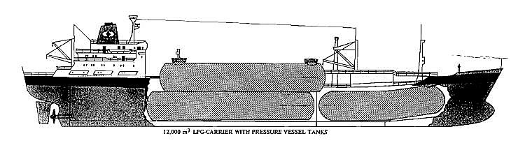
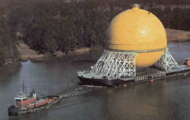
Fully pressurised ships
These ships are all equipped with independent tanks type C. The maximum working pressure can be up to 18 bar and the minimum allowed temperature is usually -5 °C, although some ships have been designed for temperatures as low as -24 °C. The first ships of this type carried their cargo in a number of vertical pressure vessels. Modern pressurised ships can have capacities between 500 and 10 000 m3 with horizontal cylindrical or spherical shaped tanks.
Cylindrical tanks are arranged below or partly below deck, mounted on cradle-shaped foundations. The tanks are equipped with domes located as far forward as possible, to avoid vapour pockets, where all connections necessary for loading, discharging, sampling and gauging of liquid level, pressure and temperature are located. Domes of tanks located below deck protrude through the deck. The combined loading/discharging pipe is located as far aft and as near to the tank bottom as possible, thus reducing the amount of cargo which remains on board at the end of discharge.
Spherical tanks are supported at their equator by a cylinder resting on the double bottom.
No deepwell or submerged cargo pumps are installed on ships of this type. Discharge is achieved by pumping vapour from another tank with a compressor to increase the tank pressure and push the liquid out. Booster pumps can be installed to speed up the operation.
Fully-pressurised ships equipped with type C independent tanks are simple, easy to build and easy to operate. The material used for the cargo tanks and piping can be normal steel and no insulation is necessary, as the cargo is carried at ambient temperature. The cargo requires no maintenance between loading and discharge and no reliquefaction equipment is necessary. The operation is very similar to that of an oil tanker.
On the minus side, the shape of the cargo tanks does not allow an optimum use of the under-deck space and, due to the high maximum working pressure, their weight and, therefore, their cost are high. As tanks increase in diameter, the wall thickness must be correspondingly increased for the same design pressure with the consequence of having to apply expensive stress-relieving procedures. Finally, the cargo quantity transported is lower per weight than for a semi-pressurised or fully refrigerated ship, due to the lower specific gravity of the cargo at ambient temperature. Above a certain tank size, it is more economical to install a refrigeration plant and to maintain a reduced pressure in the tanks.
Semi-pressurised ships
These ships are also equipped with independent type C cargo tanks. The maximum working pressure is usually limited to between 5 and 7 bar. Older ships had minimum service temperatures not lower than -5 °C, however, more recent ships can carry products with minimum temperature as low as -48 °C (or even -105 °C for ethylene tankers). The tanks are usually horizontal, cylindrical or bi-lobed, mounted on saddle supports. They are internally stiffened with wash bulkheads and stiffening rings notched top and bottom to allow vapour and liquid flow. To minimise heat flow into the cargo tanks and to protect the ship structure from the effect of low temperatures, a thick layer of insulation is required all around the tanks. The insulation material is usually polyurethane foam or polystyrene, pre-formed or projected, covered by a moisture-tight protection, usually made of aluminium foil. The thickness of the insulation material depends on the minimum temperature at which the cargo is carried. The refrigeration or reliquefaction plant maintains the temperature of the cargo by removing the boil-off vapours from the tank and returning them in liquid form. The tanks usually have two domes to accommodate all piping and instrument connections. The vapour dome, located approximately at the middle of the tank where the vapour line, pressure exhaust valves vent line and level gauges are located and the liquid dome, located on the aft-part of the tank, where the liquid loading line and cargo pump discharge lines are connected. The cargo piping connections are usually equipped with expansion loops or bellows to compensate for movement due to changes in temperature. Deepwell pumps, with the electric motor outside the tank and a long shaft reaching to the bottom, are favored for this type of ship and it is usual to have only one pump installed in each tank. In case of pump failure, the compressors can be used to establish pressure at the top of the tank to push the liquid out.
Booster pumps and cargo heaters are usually installed to allow cargoes to be loaded or discharged at any temperature and transported in a refrigerated condition. A number of different cargoes can be carried simultaneously, even in refrigerated condition and different grades of product can be loaded or discharged at the same time without the possibility of any mixing.
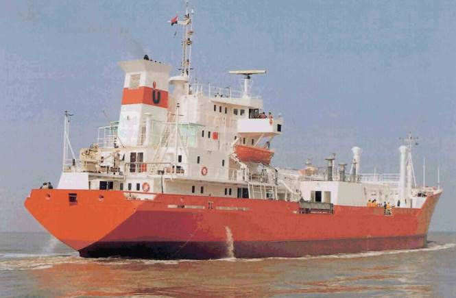
Semi-pressurised ships are more expensive than conventional pressurised ships but their flexibility in service makes them very popular in the trade. As independent tanks type C do not require a secondary barrier, they can even be competitive with the fully refrigerated ships. Current sizes for semi-pressurised ships are between 5 000 and 12 000 m3, but ships as large as 20 000 m3 are currently being built.
Type C tanks with a minimum service temperature equal to or above -50 °C are usually built of fine-grained carbon-manganese steel, as recommended by the Code. Tanks for semi-pressurised ethylene tankers, with a minimum service temperature of -105 °C, are built of 5 % nickel steel or stainless steel.
The advantages of semi-pressurised ships can be summed up as follows:
- Cargo weight to tank weight ratio is 4:1 compared with 2:1 for pressurised ships.
- Great flexibility in the conditions accepted for loading and discharging cargoes.
- Higher specific gravity of cargo due to low temperature of transportation increases the quantity loaded for an equal volume.
- Savings due to reduced tank wall thickness are balanced by extra costs due to the need .for higher quality materials and reliquefaction equipment.
Fully refrigerated ships
These ships are all equipped with prismatic, independent type A tanks, which, according to the Code, require a full secondary barrier. As the cargo temperature is usually limited to -50 °C at the lowest, a double hull is not required. A few of the early ships were provided with a double hull extending over the full length of the cargo containment space, the inner hull being of low temperature material and acting as the secondary barrier. The space between the two hulls was used to carry liquid petroleum products. However, after the catastrophic accident of the YoyoMaru in Tokyo Bay, this practice was discontinued. In modern ships, the double hull extends over the bottom bilge area only. The secondary barrier is provided by special steel for the double bottom and bilge chamfer, the side shell and associated structure extending between the bilge chamfer and the bottom of the hopper tanks and the inside plates of the hopper tanks. Transverse bulkheads separate the holds, either single plate or in the form of a Cofferdam – Definition and Pronunciationcofferdam.
The maximum service pressure of this type of tank is limited to 0,25 bar. The tanks are equipped with a vapour dome in the centre and two liquid domes, one on each side on the aft-part of the tank. The tops of the tanks have inclined chamfers to limit the effects of free surfaces, for stability reasons. The bottoms are rounded to fit the ship’s structure in the bilges. A longitudinal bulkhead divides the tanks to limit the effects of sloshing. The tanks rest on a series of wooden supports, isolating the ship structure from their low temperature. Anti-flotation and anti-rolling chocks are installed to prevent the tanks floating off their supports in the event of flooding of the holds and to support the tank sides in case of heavy rolling.
Each tank is equipped with two Equipment and cargo system of LNG onshore terminalssubmerged cargo pumps with the electric motor installed at the bottom of the tank. Some ships are equipped with deepwell pumps, although, for the larger size ships, very long shafts are required. The foot valve at the bottom of the longitudinal bulkhead allows the whole tank to be discharged by only one pump in case of malfunction of one of the pumps.
Independent tanks type A with a minimum service temperature above -50 °C are usually built of fine-grained carbon-manganese steel.
The IGC Code recommends specific materials for the construction of cargo tanks. The recommendations are based on the minimum service temperature and also on the compatibility of the material with the cargo to be transported. The IGC Code specifies lower service limits for different grades of material depending on the evaluation of all factors affecting the safe use of this material, including fatigue, stress, thickness and quality of welding. Steel suppliers put their products through special approval testing procedures throughout the manufacturing process. Welding is also an important part of the tank construction and the filler material used is the object of very accurate specification. Welding joints are very carefully checked for default by non-destructive methods. The extent of these checks is also specified in detail.
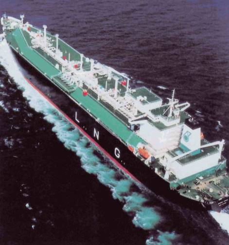
Insulated ships for LNG
These ships currently use insulated tanks of either the membrane type or the self-supporting prismatic or spherical type B.
We have seen that earlier ships were fitted with tanks of the self-supporting prismatic type A, in aluminium alloy material, with either a full secondary barrier made of the same material (ESSO type) or a combination of balsa wood and plywood (Conch type). Then the membrane types were built (Gas Transport and Technigaz), followed by the self-supporting spherical type B tanks in 9 % nickel steel or aluminium (Kvaerner-Moss) and the prismatic self-supporting type B aluminium tanks (IHI). These are the tanks which, up to now, have been selected for the construction of ships used in commercial ventures. Meanwhile, a large number of other designs were patented, some completely original, others being variations of existing successful ones. A number of these projects were designed in sufficient detail to be proposed for commercial use and a few were even used in the construction of small, prototype vessels.
It would take too long to describe all the designs presented through the years which, in some cases, never got beyond the stage of a nice sketch on a piece of paper. A very comprehensive list can be found in the excellent book «Natural Gas by Sea» written by Roger Ffooks, one of the original designers of LNG containment systems. It is interesting, however, to list some of the more realistic ideas, to show the level of enthusiasm generated by the prospect of discovering a successful containment design to be used in the construction of LNG ships. This interest still exists and there are, today, groups of designers still trying to create new LNG containment systems which might attract prospective ship-owners.
Many designers tried to emulate, with some variance, the original design of the self-supporting spherical type B tanks by Kvaerner-Moss. The different designs varied only in the shape of the sphere support system, as it is difficult to make one sphere look different from another. The more notable designs came from France, with Gazocean, the US, with Chicago-Bridge, the US and France, with Pittsburgh-Des Moines associated with Gaz Transport, Spain, with Sener and from Japan with Hitachi-Zozen. However, Kvaerner-Moss has, to date, retained the exclusivity of the spherical design for LNG tanks.
The semi-membrane principle attracted many designs, but none were commercially successful. These were from the UK, with Conch and Albiach, France, with Chantiers de l’Atlantique, Germany, with Linde, Spain, with Sener and from Japan, with Bridgestone and IHI.
Another system which attracted the attention of many designers whilst also eluding the expected commercial success was the internal insulation system which would allow the tanks to be constructed in normal steel. Designs came mainly from the US with Rockwell International Wet Wall, Owens Corning Perm-Bar II and Mc Donnell Douglas, who also tried to use the insulation in association with the Gaz Transport membrane system and from Spain with the Metastano Internal Insulation.
Some designers thought that carrying LNG at a higher pressure would have some advantages but this complicated the design by introducing multi-container systems and buyers were not tempted. These systems came from Germany, with the LGA Zellentank, the Linde Curved Wall, the Linde Multi-Vessels, Holland, with the Verolme Vertical Cylindrical and from the USA, with the very high pressure Ocean Transport Pressure System, which eventually evolved into the much lower pressure Ocean Phoenix Transport.
Some other designs were resolutely original in their concept, such as the McMullen double-wall system or the Dytam Concrete LNG Design. However, they were equally unsuccessful.
As can be seen from the listing above, there was no shortage of inventiveness and determination in the LNG industry. And let us not forget the proposal to build 200 000 m3 LNG submarine tankers, with liquid oxygen tanks to supply the boilers, for the transportation of LNG from North Canada, under the ice pack! Such is the enthusiasm which the prospect of the rapid development of the LNG industry has always generated.
However, all LNG ships ordered within the last 20 years have been of only four different designs:
- The self-supporting spherical tank type B from Kvaerner-Moss.
- The Gaz Transport Membrane system.
- The Technigaz Membrane system.
- The self-supporting prismatic tank type B from Ishikawajima-Harima Industries.
These four designs will be examined in more detail.
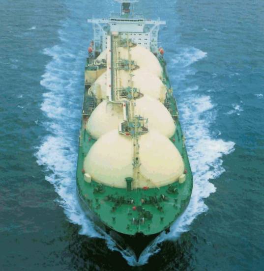
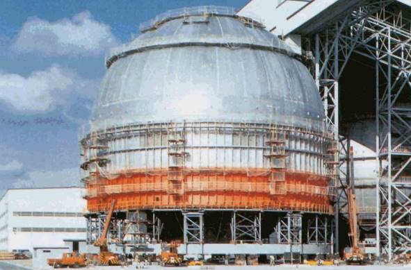
Spherical tanks
The first LNG carrier with spherical tanks was built in the Moss Rosenberg shipyard in Stavenger, Norway, in 1973. This was the 87 600 m3 Norman Lady, with tanks in 9 % nickel steel. The Kvaerner-Moss spherical tank design is the only LNG containment system to have been built commercially without prior prototype testing.
However, the designer was confident that the extensive studies and supporting test work completed prior to the construction of the first ships had proved that the design was safe and practical. These studies included the following work:
- Study of wave loads and ship motion including shear forces, bending and twisting moments, acceleration and liquid motion in the tanks.
- Study of the connection between tank and support at the equatorial ring by finite element and photo-elastic analysis and fatigue testing.
- Thermal stresses in the tank shell, particularly in the equatorial zone, torsional response of the hull and its effect on the spheres and their supports and stability of the tank and supporting skirt under different loading had been the object of a detailed structural analysis.
- Detailed analysis of the cargo containment system, its insulation and the general arrangement and operation of the cargo equipment.
- Detailed investigation of the properties of 9 % nickel steel particularly its fatigue behaviour and crack propagation characteristics under various stress levels.
The Kvaerner-Moss confidence was justified as, at the end of 1999, there were 63 LNG tankers (54 % of the total fleet number) of various sizes equipped with spherical tanks in service around the world, with another 8 on order. Sizes vary from 19 000 to 138 000 m3.
Although the two first ships were built with tanks in 9 % nickel steel, the design was won changed to aluminium and all subsequent ships were built with aluminium tanks. Due to the perfect geometrical shape of the sphere, it was easy to carry out finite element calculations to determine the level of stress and the extent of possible crack propagation. Based on these calculations proving that it is impossible for a crack, in any circumstances, to propagate into a catastrophic failure, it was admitted by classification societies and confirmed by the IMO IGC Code that the spherical tank type B does not require a full secondary barrier. The only requirement is for a drip-tray at the bottom of the hold to prevent any possible dripping of cargo, resulting from a limited crack, to damage the ship’s structure.
The other main characteristic of the spherical tank designed by Kvaerner-Moss is the way the tank is supported. This is achieved by having a continuous cylindrical, stiffened skirt attached to the equator by a special extrusion allowing the sphere to expand and contract freely with minimum load being applied to the shell. The skirt is itself welded integrally to the hull structure and is subjected to the hull’s deflexions which it has been designed to absorb.
The extrusion at the equator of the tank and the top of the skirt are aluminium and the bottom of the skirt is low temperature carbon steel. The link between the two parts is composed of a structural transition joint made of aluminium alloy, titanium, nickel and stainless steel joined together by explosion bonding and a thermal break made of stainless steel to reduce the thermal leak between the tank and the ship structure through the skirt. With this system, it is claimed that boil-off rates as low as 0,10 % per day can be achieved.
Tank insulation varies slightly from yard to yard, but it is basically formed of several layers of cellular foam of various compositions, covered by a vapour barrier in aluminium foil or fibreglass to prevent any ingress of moisture inside the insulation when the temperature is lowered. The thickness of the insulation is dependant on the amount of boil-off deemed acceptable for the project for which the ship is built. The holds around the tanks are kept under an atmosphere of either inert gas or dry air.
The Kvaerner Moss spherical tank design continues to enjoy considerable popularity among owners of LNG tonnage and this is confirmed by the steady number of LNG tankers with spherical tanks ordered during the 1990’s.
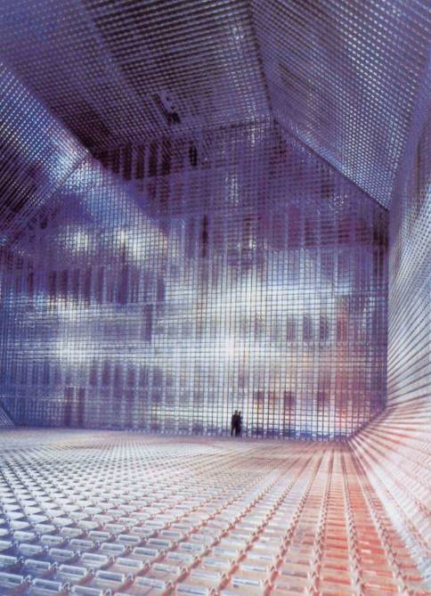
Membrane tanks
There are two different designs of LNG membrane tanks: the Gaz Transport design and the Technigaz design. Both systems were developed during the 1960’s. The first prototype of a Gaz Transport membrane containment system was installed on the 30 000 m3 LPG tanker «Hypolite Worms» in 1967. The first LNG tanker equipped with the full design was the 71 500 m3 «Polar Alaska», delivered by the Kockum shipyard in 1969. The first prototype of a Technigaz membrane was installed on the 630 m3 «Pythagore», delivered in 1965 and used mainly as an LPG and ethylene tanker. The first LNG ship equipped with the full design was the 50 000 m3 «Descartes», delivered in 1971.
Both Gaz Transport and Technigaz designs use thin flexible steel «membranes» to contain the cargo. The membranes are surrounded by insulation material applied directly on the ship’s double hull and the weight of the cargo is transmitted through the insulation and supported by the ship’s structure. This is as far as the two designs can be compared. The detailed concept and realisation of each system are very different, one of the major differences being the material used to make the actual membrane.
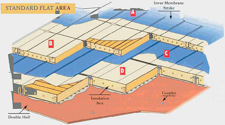
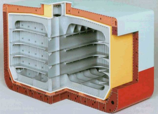
The Gaz Transport system uses a 36 % iron-nickel alloy known as Invar, produced by Metal-Imphy. This material has an extremely low expansion coefficient which allows the use of flat panels for the construction of the membrane. This facilitates the welding operations and makes possible the installation of a second membrane, symmetrical to the first one, which acts as the secondary barrier. The system includes two layers of insulation, the first located between the two membranes, the second between the second membrane and the ship’s hull. The insulation comprises a series of plywood boxes containing perlite powder. In order that the sealing membranes follow the hull flexing, due to wave motion and cargo pressure, the insulation/membrane interface allows independent movement of one in relation to the other. All the components of the system are integrated in a modular assembly with the size of the insulating boxes (1 × 0,5 × 0,3 metre) corresponding to the width of the membrane streak (0,5 metre × 0,7 millimetre) extending the whole length of the tank. As in the case of spherical tanks, the thickness of the insulation is decided by the level of boil-off required.
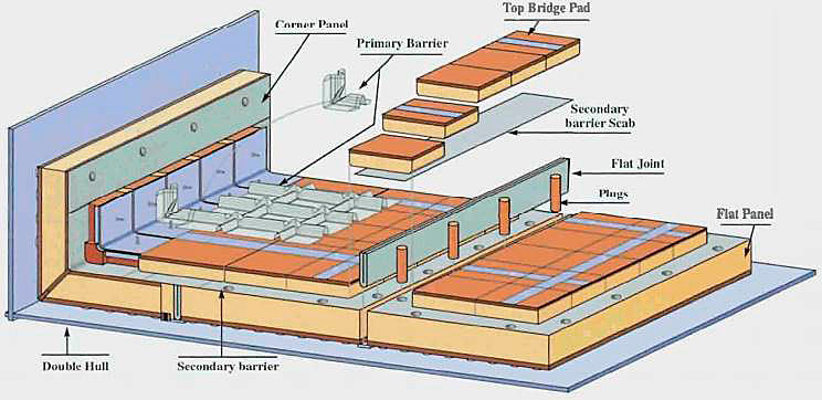
The Technigaz system uses a very low carbon content stainless steel. To compensate for movement due to temperature change, orthogonal corrugations, allowing extensive expansion in two directions under a light load, are formed by folding the membrane. The insulation, which, on the first ships, was balsa wood, is now expanded polyurethane foam reinforced with fibreglass and the secondary barrier is made of a composite material, comprising a thin sheet of aluminium glued between two layers of glass cloth. The thickness of the membrane is 1,2 millimetre and that of the insulation is dependant on the expected boil-off.
In both Dynamic Strength Analysis for Membrane Type LNG Containment System Due to Sloshing Impact Loadmembrane systems, the insulation spaces surrounding the membranes are maintained under an atmosphere of nitrogen and are constantly monitored for any possible presence methane, which would indicate a leak, however minimal, through the membrane.
The name «membrane», which has been generally adopted to describe this technique, is not necessarily appropriate, as it gives the impression of a sheet of very thin material. Most car makers use body panels 0,7 milimetre thick, the same thickness as the Gaz Transport membrane and almost half of the Technigaz membrane.
A total of 48 LNG tankers equipped with membrane type tanks were in service in the world at the end of 1999, with another 8 on order. Size from 18 500 to 138 000 m3.
Read also: Preparation, Operations, and Considerations of Liquefied Gas Tanks Aeration
After many years of negotiation, Gaz Transport and Technigaz merged in 1994. The new organisation is working hard on developing a new design which will incorporate the best of the two techniques. It is understood that this new design will be ready for commercial use in the first years of the new century. In the meantime, the two existing designs have been regularly improved and are enjoying continned success, as confirmed by the many orders for Gaz Transport and Technigaz LNG tankers placed during the 1990’s.
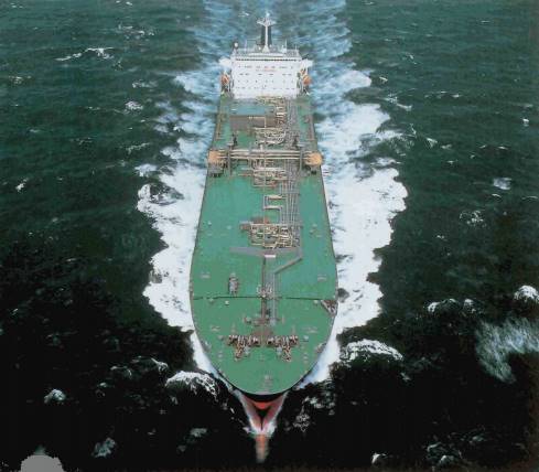
Self-supporting prismatic type В (SPB) tanks
Self-supporting, Prismatic type B tanks were developed by Ishikawajima-Harima Heavy Industries (IHI) during the 1980’s. This development was based on the long experience acquired by IHI of building prismatic type A tanks for LPG tankers. The new tanks are very similar to those used in the Conch system, but the development of improved computerised finite element analysis allowed major differences to be introduced:
- The tanks are designed and built to meet IMO‘s leak-failure criteria and to be classified as type B tanks.
- The insulation is attached to the tanks and not the inner hull, and type B tanks do not require a full secondary barrier but only small leak protection.
The tanks are built of aluminium and very extensive use is made of automatic welding systems. They rest on a number of bottom supports, suitably insulated from the ship’s hull and anti-floating and anti-rolling chocks ensure that they remain in position in all conditions. The insulation is composed of panels of polyurethane foam covered with a vapour protection barrier. A longitudinal bulkhead, equipped with a foot valve, divides the tank in two and transversal swash bullheads provide the necessary reinforcement. The holds around the tanks are kept under an atmosphere of either inert gas or dry air. The boil-off rate has been set at 0,15 % per day.
After numerous presentations of their new LNG containment system to various international conferences, orders for two ships of 87 500 m3 capacity were eventually signed in 1989 for delivery in 1993.
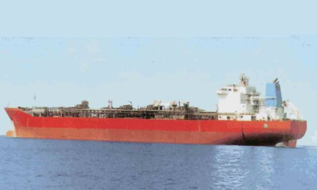
Although it is generally agreed that this containment system and the two ships equipped with it are a success, only one other order has been received by IHI for a vessel with SPB tanks. This vessel is an LPG FPSO, now in operation on the West Africa coast.