Yacht design comparisons play a crucial role in understanding the performance and functionality of various yachts. By examining aspects such as the midship section, keels, and rigging, enthusiasts can better appreciate how different designs impact sailing efficiency. Key performance ratios, including length-beam and sail area-waterline ratios, provide valuable insights into a yacht’s stability and speed.
- Construction features: viewing yachts at boat shows
- Midship Section
- Chine Sections
- Keels
- Winged keels
- Rudders
- Skeg and Distance to the Centre of Gravity
- Bow Shapes
- Stern
- Rigging
- Engines
- Propellers
- Making Comparisons of Ratios at Home
- Length-beam Ratio
- Sail Area-Waterline Ratio
- Length-displacement Ratio
- Sail Area-displacement Ratio
- Sail Area-length Ratio
- Sailing Speed-waterline Ratio
Additionally, the choice of bow shapes and stern configurations can greatly affect overall maneuverability. Whether viewing yachts at boat shows or analyzing designs at home, these comparisons help sailors make informed decisions. Ultimately, understanding these elements enhances the overall sailing experience.
Construction features: viewing yachts at boat shows
The design features of a boat will allow you to assess whether it has been built for speed, rough seas, light winds or only for day sailing. With the information given in the following chapters, you should be able to determine a boat’s character, i. e. whether it is course stable, cuts smoothly into seas, or whether it requires stronger winds in order to reach the hull speed.
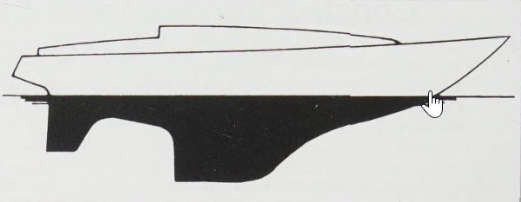
Lateral Plan. The first thing to catch your eye when looking at a docked yacht is the lateral plan. This is the term for the lateral area of the underwater hull. Ir is part of the yacht’s overall picture, and although you can probably see the length of the boat above water from the profile, the lateral plan will provide better information regarding the yacht’s characteristics. After all, it has to produce the lateral force in the water to counterbalance the force of the sail and simultaneously provide course stability. Here, the flattened surface area is the first priority.
Boats with flat lines and fin keels make things slightly more difficult, because the lateral profile and the keel profile offer sufficient buoyancy. They can be compared to the main features of a hydrofoil, even if the keel hangs vertically in the water. It follows (see Choosing the Right Yacht – Essential Considerations for Every Sailor«Manoeuvrability and course stability») that the longer and narrower a wing, the more buoyancy it produces and the narrower (theoretically) can be its profile.
The best option for a cruising yacht is a compromise between the width of the keel and acceptable draught. A wide keel (approaching long keel) also has a better keel-to-hull transition. The distance from the keel to the rudder is also of interest; the rudder is more effective the longer the lever is between the keel’s and rudder’s centre of effort. Another important consideration is whether the designer provides a skeg or whether the rudder hangs freely. A skeg produces a free water flow around the rudder and provides additional lateral area for a better course stability. The lateral plan also displays whether a boat reacts sluggishly or sensitively to rudder movement and whether it needs drive to stop the boat from drifting. A narrow fin always needs speed for developing buoyancy. A large lateral plan also has higher friction resistance because of her large wetted surface. The proportion of the rudder’s area should be 5-7 percent of the lateral plan for a long-keeler and 10-12 percent for short-keeled boats. Yachts with these values have proved to be easy to steer.
Midship Section
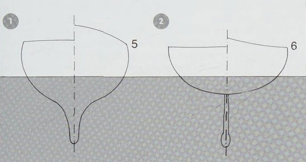
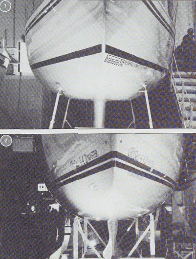
A complete drawing plan that provides a two-dimensional view of all sections offers you the best idea of a boat’s hull shape. These drawings are seldom available, so you will have to be satisfied with the midship section. The midship section is where the boat’s widest beam is. It describes the largest circumference and cross-section. If you are unable to obtain a drawing, you can instead view a boat from the front and back at a boat show or in boatyards (take a photo). It will allow you to find out more about the boat’s character. A car’s equivalent to the midship section is its so-called «frontal area», which is used for determining the CW-value. The midship section is also of importance for the resistance. As the cross-section of the yacht’s submerged area, the resistance is a criterion for the cylinder coefficient that was mentioned in Choosing the Right Yacht – Essential Considerations for Every Sailor«Fast sailing» and described on p. 97 in the Appendix. At first glance, the section gives information on storage space, living area and headroom and also clarifies the bilge section. The shape of the midship section permits assumptions regarding form stability; flat, bowl-shaped ones possess a larger righting moment than semicircular ones.
The shape of the keel displays the lateral force and the circumference of the midship section will tell you whether the wetted surface of the boat will be large or small. For a fine-weather boat you should choose re narrow hull shape of a heavy displacement yacht, and for a heavy-weather boat, the wider hull shape.
Chine Sections
Again and again you will come across boats with hard chine sections, although this building method is not necessary for fiberglass yachts. It is a simple and cheap method of construction used for boats made of plywood or steel, as the material is simply planked without compound curves used corners are more difficult to produce in fibreglass yachts. Some designers still seem convinced of the superiority of their fibreglass hard chine construction, although surveys have proved them wrong – at least wit cruising yachts, which generally dont exceed their hull speed. At low speeds, round-bilged hulls definitely ow lower resistance in the water and are therefore faster.
Only in planing conditions – mainly motorboats with sufficient speed – does the hard chine construction show an advantage. When a hard chine hull displaces water, it produces a premature detachment of the stream flow, which is the reason for the higher resistance. This makes the hard chine shape only sensible for ultralight constructions that are sailed to plane or for self-builders who are able by this means to obtain a larger yacht.
Keels
Nowadays, long-keeled yachts are often regarded as heavy motorsailers. With lighter yachts, the choice lies between keels with small aspect ratios or fin keels with large profiles. A cruising yacht’s keel should be closer to a long keel, so that the boat is able to use shallow harbours and is also in a position to fire safely in drying harbours. The area of such a keel should be about 4 percent of the sail area.
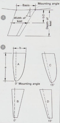
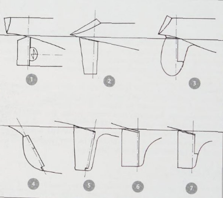
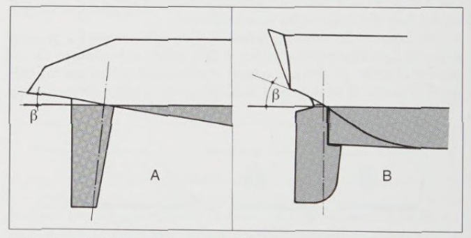
Keels are often mounted so that they slope aft. If this has no practical reason, i. e. attachment to the hull or shifting the ballast further aft, there is no reason to do this – though one exception might be in boats with a large fin area relative to draught, as these can achieve greater effectiveness by sloping the keel aft.
The keel’s profile is important for a good lateral force: the curve of the front edge, the largest thickness of the profile in relation to length and the position of the greatest thickness all have a profound effect on efficiency. NACA profiles (as already mentioned) are generally used, which are assembled and already calculated in the book Theory of Wing Sections (Dover Publications). In designer circles, these profiles are known as the measure of all profiles. NACA profiles have an elliptic inlet (front edge) and an acute outrunning end. They are a sign of good buoyancy to windward and are evidence of the fact that the designer has given some thought to the hydrodynamics of this boat.
A keel’s circumference is also of important with regard to a boat’s lateral force underway: if you disregard long narrow fins as only suitable for Popular Types of Yachtracing yachts, you will find that rectangular keels offer slightly morebuoyancy than trapezoid-shaped ones. Keels with an elliptic circumferenceare slightly more favourable, For practical reasons, you should choose a long bottom edge that runs parallel to the waterline (for a cruiser), so that the boat can easily be placed on its winter hard standing.
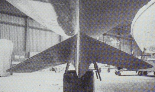
Winged keels
Some cruising yachts have adapted the winged keel (keel with side-wings) after it appeared on the successful 12 metre yacht Australia II. The argument was that it would give more height to windward with less draught by concentrating the ballast in the wings. This has proved to be untrue. The flow around the keel (like a hydrofoil) might be bettered (like the end plate, which prevents the flow from drifting away), bur this advantage turns into a disadvantage in heavier seas when the boat is pitching.
The draught can only be reduced if the proportion of ballast is increased, because the righting lever becomes smaller. This would be more effective with a «bulb» at the bottom end of the keel. If the bulb keel is also designed as a hydrodynamic shape like the Scheel-keel, it will be even better. The special lines of this keel, as used by many designers, have originated in a test tank and look rather iron-shaped.
Rudders
If a sailing boat is left to its own devices it becomes unstable around its vertical axis with regard to headway. Course stability is produced by the rudder, which reduces the yawing and steers the boat. Rudders of older- style cruising yachts are placed at the aft edge of the conventional long keel, which makes these yachts difficult to turn but extremely reliable in heavy seas. With the appearance of the divided lateral plans, as in the fin keels, the rudder was elongated and moved further and further below the stern to give stability.
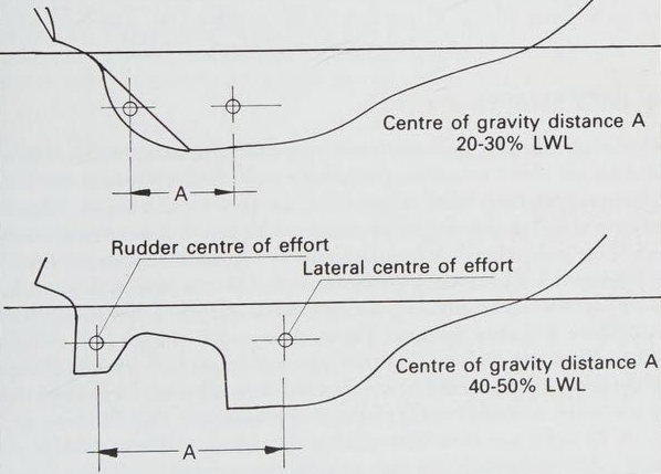
Counterbalancing the rudder’s centre of effort with that of the keel and the sail area is an art that is not possessed by every designer. The rudder should have an optimal effect in every heeling angle, but this is often not achieved. For balance reasons, the geometrical lateral centre of effort should be behind the sail’s geometrical centre of effort; applied to the waterline, the distance required between both centres is between 10 and 15 percent.
Rudders can be built like keels, preferably with a large aspect ratio: long and narrow. The NACA-profile offers a very good rudder movement, but is very sensitive and is nor forgiving of mistakes. If the angle of the rudder is too large, the stream of water cuts off and the boar shoots off course.
Smaller ratios of rudder profiles are less critical. A good investment for Cruising in Comfort on a Sailboatcruising yachts is also a skeg, as free-hanging spade rudders are more suitable for racing yachts, and most sailors will not require that much sensitivity.
Designers like a balanced rudder blade so that the rotating axis does not affect the front edge of the rudder; and any effects will be experienced somewhere aft, The rudder area is therefore divided into a front area and 2 balanced area. Depending on whether the rudder’s centre of effort lies in front or aft of the rotation axis defines the terms under- or over-balanced rudder. A balanced rudder puts less pressure on the tiller because the front area supports the required force. The ideal rudder should have its centre of effort slightly behind the rotating axis, so that the helmsman still feels a little pressure on the rudder.
Cruising yachts should sail with a slight weather helm, which is also optimal for the rudder. The rudder has to be set at a slight angle, so that the stream from the keel catches the rudder at a favourable angle.
Rudders of modern yachts are generally positioned directly under the stern in order to achieve the best steering. You can check out whether your dream boat is designed in this way.
Part of the rudder is lifted out of the water if the stern is lifted by waves coming from behind, or if boats with a beam quarter are sailing with a large heeling angle. You should pay attention to this when buying a boat. A partial solution to this effect would be a deep rudder with skeg. Spade rudders in particular lose their efficiency when heeling at large angles because a cavitation effect causes the rudder to suck air and renders it totally useless.
Skeg and Distance to the Centre of Gravity
The rudder area is a part of the lateral area, so it makes sense to design it large in order to increase the lateral plane for a reduction of the leeway. The disadvantage is that it places larger forces on the rudder. The skeg in front of the rudder is therefore a good solution in various respects: the actual rudder area is placed safely behind the fin and is easier to mount, The boat is also easier on the rudder, if it is not too lively, and does not oversteer as readily.
The skeg serves as a good leading edge for the rudder. The rudder can also be partially balanced behind this area. A cruising sailor’s most important argument for a rudder with a skeg is that mooring lines, plastic bags and weed or barnacles can cause little damage. Such things are always a threat to freestanding rudders.
The distance between the lateral areas of keel and rudder are vital to the effectiveness of the rudder. Momentum develops when moving the rudder (force times righting lever); thus, the shorter the distance between the centres of effort, the smaller is the effectiveness of the rudder. If a long-keeler is compared to a fin-keeler, it becomes obvious (apart from the fact that there is water flow between rudder and keel) that a long-keeled boat manoeuvres more sluggishly. Its rudder momentum calculates levers with values between 20 and 35 percent of the length of the waterline, while short-keelers achieve levers between 40 and 50 percent LWL.
Bow Shapes
The bow shape gives the yacht its characteristic appearance and is responsible for the way it cuts through the water and whether it sails dry or wet, This has little to do with the angle of the bow (seen from its side), i. e., whether it is extremely angled or straight, with hollow lines (clipper bow), or convex (spoon bow). A straight bow only increases the flotation line.
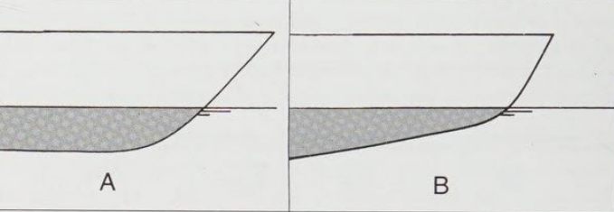
Bows with a classic deep forefoot (usually in connection with a pointed V-shaped bow) contribute to good sea behavior. Extreme fin-keelers generally have a shallow forefoot. On modern yachts you generally find a shallow forefoot which turns into a trapezoid-shaped hull. You can already recognize this on the hull bottom in the forward area. In squalls, this prevents the increased weather helm that is common with flat-bottomed boats. In slight seas these bows sail without a large bow wave, and if the boat is light enough – rarely the case with cruising yachts – it planes more easily. In heavier seas it pounds more quickly, unless sailing with a sufficiently large heeling angle. In such cases, the edge of the trapezoid section enters the water first and not the flat bottom. The fullness of the bow and the angle it cuts into the water – or, if you prefer, the sharpness of the bow – becomes important, A sharp bow that runs into a pointed forefoot has less resistance in the water than a fuller one, However, beat like this can carry less sail as it has less buoyancy. If it could carry a large genoa, it would probably undercut. For these boars, designers have allowed for a smaller genoa or constructed the boat with a fractional (7/8)-rig.
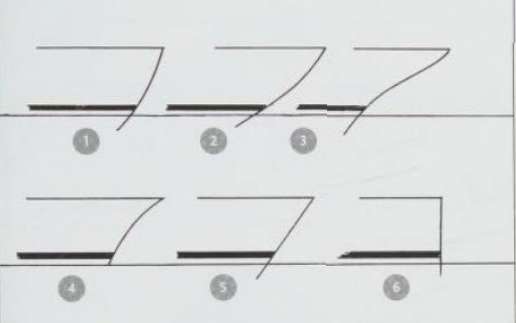
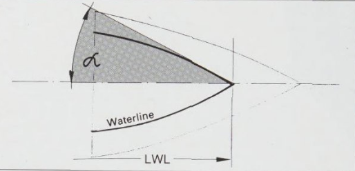
In order to cut smoothly into the sea, the bow and the shape of the forefoot should be designed to produce more buoyancy when further dipping into the sea, i.e. smoothly cutting into the water without abrupt braking effects. The angle at which the boat cuts into the water is also known as the angle between the waterline and the longitudinal axis of the boat (see above). It is dependent on the breadth and the position of the midship section and determines the bow shape.
The admission angle (point of entry into the water) of small boats (i. e. less than 8 metres) is determined from the required with of the bottom end of the forepeak berths. As they generally come together with the hes line, you can measure the admission angle at this location: it should nor exceed more than 26 degrees for a seakindly yacht (see p56*).
The shape of the forefoot determines the trim of the yacht when heeled. If it is too narrow, the stern lifts when the boat heels, which slows down the speed and the bow will probably undercut. In addition, you would have a lot of pressure on the rudder and bad manoeuvrability.
If the forefoot is toobulky, the stern will be pressed on to the water and the bow lifts. This also reduces the speed, the boat goes off course, and the action of the rudder exacerbates this further. The relation between bow and stern should there- fore be balanced. The position of the midship section (on the middle of the waterline length) serves as a good indicator.
| V/√LWL | α (IE) |
|---|---|
| 0,5 | 30° |
| 0,6 | 26° |
| 0,7 | 22° |
| 0,8 | 18° |
| 0,9 | 14° |
| 1,0 … 2,0 | 10° |
Stern
The stern influences the yachts performance even more than the bow. While a wide bow may enhance speed at some points, a badly constructed stern which has no clean stream flow is useless. The boat gets out of trim and drags through excess water turbulence. One old boat builder’s rule says «A boat must lose water at the stern», and this still applies. The stern should therefore be designed accordingly: if a natural water flow follows its natural lines, it will flow smoothly and without interruption. It can then stream off the stern without turbulence – and it is turbulence that creates unnecessary resistance. The wave resistance that stops a boat’s drive increases the higher the stern wave develops. You recognize this on the steep slope of the run aft. It leads the water unnecessarily high without letting the flow cut off. A boat with a flat hull shape and correspondingly flat stern sails faster than a boat that lies deeper in the water and has a poorer water flow.
The height of the stern wave provides a good indicator of performance. While a pointed stern is sufficient for a rowing boat (normally the most favorable hydrodynamic form to lose the water), a yacht’s stern needs to be wide, because of the higher speed, with more displacement so that it does not drop into the wave trough that develops at the stern. The faster a boat, the longer is the wave it sails on.
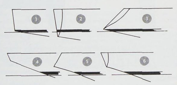
Flat sterns arise naturally, following through from the flat midship section in light displacement yachts. A light weight only displaces a small amount of water, so that less volume is submerged: this allows the hull shape to be flat. If more weight, i. e. displacement, is added (as is generally the case with cruisers), the midship section needs to become deeper; this automatically results in steeper sterns that are then only useful for Keel Types Comparison and Additional Design Considerations for Sailboatsdisplacement boats. If you want to exceed this, the boat has to become lighter. The IOR racing rules punish flat sterns (so that the advantage of extreme designs is not as great). This is why some designers built sterns that sloped unnecessarily steeply and, in essence, designed poor boats.
Even displacement yachts should not have a declining angle (indicates the steepness of the stern) of more than 20 degrees. A yacht with a larger displacement astern has a longer breadth waterline, which produces more resistance at low speeds and lifts the rudder our of the water when the boat is heeled. Excessive hollow stern shapes indicate that the boat is heeled. Excessive hollow stern shapes indicate that the boat «sucks water» when the speed increases, Flat stretched stern shapes indicate speeds exceeding the hull speed, so long as the stern is not overloaded with holiday gear – and the crew trims the displacement centre.
Rigging
A yachts rig produces the forward drive: to windward through air flow on the sails’ profile; before the wind by building up pressure in as much canvas as possible. You can already detect from the rig whether the vessel is a stable cruiser or a fast racing boat; while the first is built more solidly, fast boats generally have slimmer mast profiles and as little rigging as possible. The rigging is attached so as to form the lowest resistance possible for the wind.
A “fast” rig can also be suitable for a cruising yacht, so long as it is both strong and simple, although in strong winds the length of the hull’s waterline in any case limits the boat’s speed (rarely more than 2,43 √ LWL). In lighter winds with speeds below the hull speed, a high-performance rig can extract more from the wind by allowing an optimal mast tune for a better trim of the mainsail.
The wire rigging of many cruising yachts could be improved by orientating itself to racing boats, because the rig with most stays is not necessarily the most solid or even the most effective: the sail drive should be designed for courses close to the wind. Therefore, it is important to have a well-fixed rig without unnecessary air resistance, and a stiff boat that offers the wind a large sail area without much heeling. All other courses will then follow naturally.
The most effective rig is one with the largest stretch of sail, which means the higher and narrower (at equal area) it is, the faster it sails. Cruising yachts, regardless of whether they are fast or slow, should be easy to handle as they are mostly sailed by families. They therefore require a simple user-friendly rig, which is still easily adaptable to the wind conditions. The less complicated the construction, the better. The masthead should be kept simple; this applies to the halyards, but also to the stays.
Masthead rigs. Most cruisers are masthead-rigged sloops (single-masted sailing boats), as was the case with RORC racing yachts during the 1960s. Because this type of rig can be very solid, at times having several crosstrees, it has proved itself right up to the present time and is still in use. Cruising yachts should not adopt the extra-large foresails and the narrow main, as these represent the 1960s racing formulas and require continuous sail changes. The disadvantage of the masthead rig is unwieldy foresails with large winches, as well as little opportunity for trimming. The advantage is the simplicity without running backstays.
Fractional Rigs.
This type of rigging is currently in favour, although it is not new. It is more flexible than the masthead rig. Because the forestay is attached to the mast at about 7/8 of its height (the measure is not fixed – it could also be at 3/4 or 5/6 of the mast height), it allows the masthead to flex in gusts. This slackens the leach and stretches it automatically when the gust is over, just as it should do. If the mast is slightly flexible, the mainsail will flatten automatically in stronger winds. However, the fractional rig requires running backstays that have to be set accurately, and these might stretch the capabilities of a family crew when tacking or gybing in heavy-sea conditions. The advantage is a handier foresail, which is usually quite small.
You will also not require two different-sized foresails, as the fractional rig gets its main drive from the (large) mainsail, which is also easy to handle.
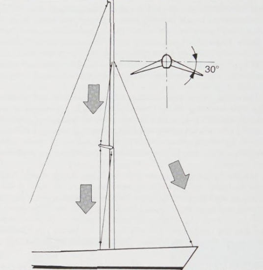
Angled crosstrees. A gentler version of the fractional rig is a mast with 25 to 30 degrees aft-angled spreaders. The angled shrouds are acting towards the forestay, which makes having a standing backstay unnecessary. This solution is not as effective as backstays, since the forestay normally sags when sailing to windward. The shrouds must therefore be extremely tight, which is only possible for a boat of up to about 10 metres. Another disadvantage is that the mainsail chafes on the spreaders and shrouds if it is let out when sailing downwind. The non-existent backstay might compensate for this.
Cutter rigs. The cutter rig has been slightly out of favour, but it is now coming back into fashion and offers cruising yachts an ideal option by dividing the fore-triangle area into a jib and staysail (instead of a genoa). An inner and outer forestay are required, and sometimes also running backstays in order to compensate for the pull of the inner forestay.
Two-masters. Of the typical two-masted boats (schooner, ketch and yawl), only the ketch is still mass-produced. From an aerodynamic view, the mizzen mast ts not worth the money. When sailed to windward it only produces resistance, and before the wind the mizzen sail blankets the main. The only time it might be useful is when sailing on a beam reach – and for carrying the radar scanner that is difficult to attach on to a sloop.
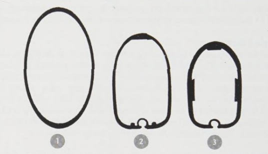
Mast profiles. An effective rig should produce as little wind resistance as possible. This applies to excessive wires, such as additional shrouds, and diagonal rigging (which is not always necessary) – and, of course, the mast profile itself. A mast that is especially thick does not necessarily mean that it is also very solid: its resistance momentum opposes the bending that is derived from the momentum of inertia.
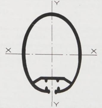
The momentum of inertia is produced from the area of the cross-section multiplied by the square of its distance from a neutral axis (see Fig 16). A thick profile wall with little distance from the mast centreline can be as solid as a small wall with larger distance. Only wind resistance and weight are different; therefore, the speed-orientated buyer will purchase the profile with the more favourable resistance.
One trick when handling thin masts is to sail them with a slight bend. With a tightened standing backstay, the mast will pump less 5 stronger winds and the material will not fatigue as quickly, This is also acceptable to a sceptical buyer who wants a solid mast. Another factor is that the sail becomes flatter, which should anyway be the aim in stronger winds; one is automatically presented with the right trim. Nevertheless, such things assist in alleviating the fear of racing rigs of many a sailor. An effective rig is not simply the one with the highest mast, but also the one with least wind resistance. Even in a force 4 it should produce sufficient energy to bring a boat up to its hull speed without excessive heeling.
Engines
The yacht’s engine must be carefully considered because it can adversely affect performance under sail: a designer who knows his job will therefore ensure that this machinery is no larger or heavier than necessary to provide auxiliary power, and will attempt to keep it sited as low in the hull as possible – perhaps even integrating it into the righting ballast. (By this token, the best site would be at the bottom of the keel, but, as this is clearly impracticable, as close to its upper surface as possible is the most appropriate location – at least here it is close to the centre of gravity and not adding undesirable weight to the ends of the boat.) In this position, however, the engine will obtrude into the saloon and not everyone is prepared to sacrifice living space or, for that matter, to tolerate engine noise. (Here, it would at least be accessible for maintenance or major overhaul, although this is not invariably so: there are cases where yachts appear to have been moulded around the engine and this makes repairs virtually impossible without dismantling joinery, and perhaps even cutting through internal mouldings.)
Largely because of the weight factor, no sailing boat should have installed an engine that is larger than necessary; no horsepower on earth will ever propel it at more than the designed hull speed. An overlarge engine may even prevent this speed being reached, since the extra avoirdupois will cause the stern to squat and thus induce greater resistance. This ts in fact a good example of the law of diminishing returns.
It is difficult to generalise about engine power, as so much depends upon the weight, shape and waterline length of the hull, and also the amount of motoring envisaged: is the engine only to be used to stem a foul tide in light airs? Or will it be relied upon to thrust the boat home through heavy weather? The best advice is always obtained from the engine manufacturer or main agent, who will also specify such matters as the maximum angle of installation (and the maximum angle of heel at which the motor may safely be run: this last a very important consideration, particularly for any yacht that makes a habit of motor sailing).
Propellers
The propeller and stern gear (be that a shaft and bracket or a saildrive unit) also have a direct bearing upon sailing performance – after all, every appendage below the waterline is a source of drag. Fin-keelers are more suited to a saildrive with folding propeller than a fixed shaft with fixed propeller, so long as the prop is situated in front of the rudder so that prop thrust streams past the rudder. It is less speed reducing because of the favourable flow around the shaft. The shaft can be designed in different ways. The form with the smallest resistance is still the folding propeller without shaft bracket. Its resistance values are below those of the saildrive. Another acceptable solution is a shaft coming out from some sort of skeg. Behind it, a two-bladed prop can be rested in “sail position”, which is probably the best compromise in order to satisfy the boat’s motoring and sailing performance. You should keep clear of shaft installations that do not possess hydrodynamically formed shaft brackets and fixed props. These systems can cause speed loss of up to a knot (see p86*).
Another piece of hydrodynamic nonsense is to run the prop in an aperture that is cut in the rudder blade. Fortunately, this solution is rarely seen these days, for the section of the rudder blade only invokes additional resistance in the form of turbulence, whereby the rudder is not subject to the optimal thrust stream of the prop. The largest part of the water stream shoots through the screw aperture, so manoeuvring under engine is difficult.
Profiled shaft brackets and saildrive shafts also add additional lateral area to the boat, although the best engine for a small boat (below 2 ton displacement) is still arguably the outboard, which can be stowed in a locker with its only contribution towards sailing being its weight. It is only good, though, if the boar sails; any inboard engine is better for motoring. The disadvantages of outboards are their tendency to emerge from the water when the boat is pitching, bad distribution of ballast (even when installed in a trunking) and poor efficiency of a small, too highly rotating prop that cannot be adapted properly (construction reasons: cavitation plate) to a displacement yacht.
Making Comparisons of Ratios at Home
Ever since yachts were first built, people have been trying to find criteria for evaluating them. Length and width are fixed, but displacement and sail area can easily be adjusted. Whether a yacht really offers a pleasant sail and whether it actually reaches hull speed in a force 3 (according to the dealer), although it is under-rigged, cannot be established at a glance. You just have to take the dealer’s word for it. Only coefficients from the boat’s main measurements can help you to evaluate a boat. The ratios allow comparisons with other boats and characterise the yacht’s qualities. The results are extremely close to measured values.
The waterline length (LWL), breadth on the waterline (BWL), displacement (V) and sail area (AS) are considered in relation to one another, as boatbuilders and designers would also do when evaluating a yacht. While professionals still use the calculator in order to obtain coefficients, all you have to do in this book is to study the diagrams: two measurements from the brochure will give you more details about the boat’s qualities. For example, in order to calculate the waterline-displacement coefficient, you read the waterline length of the horizontal axis in Fig. 19 below with the displacement of the vertical axis. This tells you where your yacht is positioned: is it a heavy or light displacement boat? Or is it somewhere in between?
Each of the introduced numbers states whether a boat is relatively narrow- or wide-beamed, over- or under-rigged, fast or slow, heavy or light. Sailing performance and sailing characteristics depend on these values, but it is difficult to view them simultaneously. Diagrams are a perfect method of determining the coefficients and offer a clear overview. The arrows indicate in which direction a boat’s tendencies lie. If you use the provided diagrams with all the boats of your choice, the decision as to which is the most suitable will be quite easy. In order to work out dimensionless values, the sail area takes its value from the second root √AS and the displacement gets the value from the third root ∛V. Therefore, you will be able to compare the displacement in m3 and the sail area in m2 and the length and width (metres) in direct relation to the other values.
Length-beam Ratio
Is the boat too beamy or too narrow? This question cannot be answered with a yardstick. You can only find out whether a boat is narrow or wide, and the resulting effects, if you put it into the context of length. The breadth of the waterline is an indicator of a boat’s behaviour at sea and her tacking qualities. When applied to the length of the waterline, it produces a number of lines that represent wide boats if they go to the top left and narrow designs if they go to the bottom right-hand corner of the diagram. Coefficients for normal Choosing the Right Yacht – Essential Considerations for Every Sailorbeamed boats are between the values of 2,8 and 3,2. The advantages for boat 1 in Fig. 17 are clear; because of its breadth, the boat is good on a close reach, but will tack badly with extensive heeling.
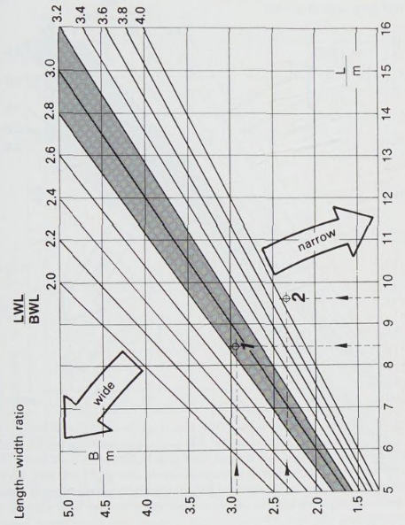
Boat 2 will be good close to windward, but will have to reef early.
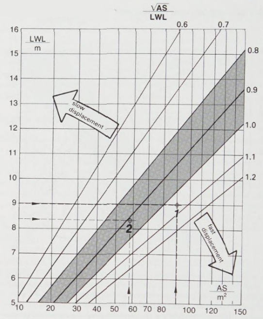
Sail Area-Waterline Ratio
Is a yacht tender or stiff? The waterline area applied above the sail area will give this information. Again, you can detect tendencies. Because the BWL is responsible for the form, or initial stability, the lines in Fig. 18 in connection with the sail area indicate some sort of sail-carrying ability that is, strictly speaking, only for boats with a high proportion of form stability, especially for centreboarders or keel centreboarders. If a keel boat is heeled, the proportion of the weight stability is added, so that it is better to put displacement in relation to the sail area.
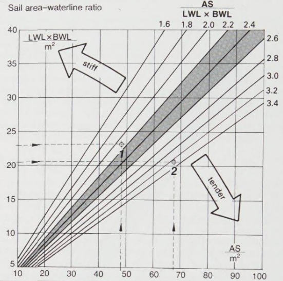
The lines differentiate in each case between a stiff and a tender boat and therefore indicate whether it behaves pleasantly or awkwardly in heavier seas. Too much initial stability (boat 1 in Fig .18) prevents smooth sailing in gusts. A yacht that Snaps upright abruptly is not very pleasant for crew and gear. The lines in the diagram also indicate how many square metres of canvas a boat has per square metre of floating water area, i. e. whether it is over- or under-canvased. This is handy for comparing boats quickly (except for extreme types). Boats with values between 2,2 and 2,6 are well-mannered at sea.
Length-displacement Ratio
Is the boat light or heavy? If you apply the boat’s displacement to the length, it will give you a clue as to whether it is light or heavy and whether it is fast or slow with equal sail area. In some literature you find the term V(LWL/10)3. A diagram allows differentiations between heavy displacement yachts, normal displacement, light displacement and ultralight displacement boats. This length – displacement ratio is a measure of how much boat weight is distributed across the given waterline. A heavy displacement boat is therefore a boat with a large displacement in the water.
Read also: RIBs and Tenders on Yachts
For our method, the ratio is more suitable the other way around, i. e. LWL/3√V (Fig. 19). The coefficients of a heavy displacement yacht lie between 4,0 and 5,0; light displacement yachts are between 6,0 and 8,0. In strong winds, boat 1 in Fig. 19 sails faster than heavier designs because of the low displacement and flat hull shape, while in light winds boat 2 will be faster. Boats with narrower hull shapes, and therefore less wetted area, have an advantage at slow speeds, because the friction resistance can be up to 70 percent of the overall resistance.
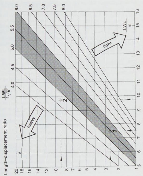
In addition, boat 2 copes better with wind pressure and choppy seas and cuts better into the water because of the pointed hull shape. A coefficient of between 5,0 and 6,0 indicates good all-round qualities. You should look for a cruising yacht that has such coefficients; variances between the boat being slightly higher or a little bit heavier are acceptable.
Sail Area-displacement Ratio
The question of whether the boat is over- or under-canvased is answered in Fig. 20 (sail area – displacement ratio). The displacement is applied on to the sail area: √AS/3√V. The coefficients state the potential forward drive in relation to the boat’s displacement (weight). The intersection of the sail area applied to the horizontal axis, and the displacement weight applied to the vertical axis, indicates the tendency of the sail area-displacement ratio.
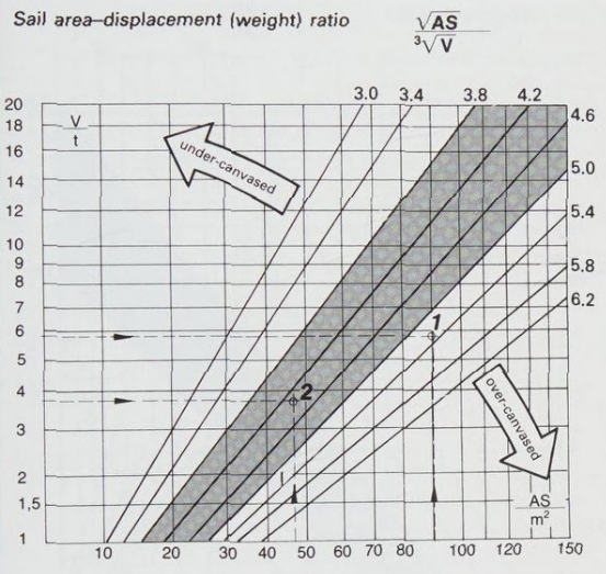
In old technical books, this relationship is known as the sail-carrying number and the size of the sail area is dependent upon the displacement. The lines allow a judgement of how fast a boat sails in medium winds. The higher the value, the more potential drive the yacht has.
A large sail area (AS) with a high displacement (V) can produce the same value as a small sail area with a low displacement, A large sail area with high displacement is faster in light winds. A large sail area is not important in strong winds, as you will have to reef down. Canvasing values with coefficients between 3,8 and 5,0 are normal. This is where most of the cruising yachts lie. Boat 1 in Fig. 20 would be over-canvased, while boat 2 could be called normal. These days, not even motorsailers are under-canvased.
Sail Area-length Ratio
Is my boat fast or slow? The coefficient that brings the sail area into relationship with the LWL (√AS/LWL) displays the forward drive of the boat in relation to her length. The boat builder’s saying “Length runs” is related to the yacht’s effective waterline, i. e. her hull speed. If a yacht is to achieve her hull speed she requires sufficient sail area.
A high sail area-length coefficient indicates sufficient sail, which uses the given waterline efficiently. For this, coefficients of 0,8 to 1,0 are generally required. Values below this indicate too slow a displacement, which is rarely found these days; values above (boat 1 in Fig. 21) describe a fast displacement yacht.
Sailing Speed-waterline Ratio
How fast can a boat sail as a consequence of its waterline length? The answer can be obtained by applying its LWL in metres and its speed in knots (VS/√LWL). Heavy boats with pure displacement lines require a sail area of 8 to 12 square metres per ton of boat in order to achieve speeds of 2,43 √LWL. The average cruiser achieves speeds of 1,63 √LWL. Only a larger sail area allows higher performance. An increase in speed is possible first through larger sail areas, i. e. more stability, and second, with a smaller length-displacement ratio (Figs. 19 and 20). In such cases, heavy displacement yachts can achieve speeds of up to 2,72 √LWL, and light displacements of up to 3,62. Only ultralights (extremely light designs) and dinghies will eventually achieve planing conditions, and thus achieve speeds of 4,88 √LWL (as measured on a Flying Dutchman).
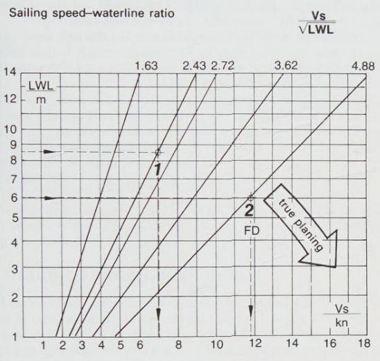
The speed-waterline coefficient clarifies the fact that high speeds can only be counted on where there is a large waterline length, because there are few extremely light cruising yachts. Fig. 21 offers a quick overview of the speed you can expect from a given boat.