This article explores the critical aspects of LNG bunkering security zones, a vital component in ensuring safe and efficient liquefied natural gas (LNG) ship-to-ship and truck-to-ship transfers. We’ll delve into the foundational principles and practical applications of these zones, from initial definitions and calculations to ongoing enforcement and operational control.
By examining the concepts of hazardous zones, safety zones, and security zones, we aim to provide a comprehensive understanding of how these measures contribute to meaningful protection and risk mitigation in the LNG bunkering process. This analysis will draw on established industry references and best practices to outline the essential elements of control and approval for these operations.
Security Zone
Unlike Hazardous Zones and Safety Zone, which are determined by the probability of presence of explosive atmosphere in the respective control zones, and the need to mitigate the risk of ignition and accident escalation, the Security Zone addresses external factors.
References
The reference standards for the definition of the Security Zone are:
| The reference standards for the definition of the Security Zone are: | ISO | The Security Zone is introduced in both documents, with a definition: |
| The security zone where ship traffic and other activities should be monitored during bunkering will always be larger than the safety zone. Physical barriers preventing other ships to approach the bunkering (e. g. like breakwaters) can be reflected in the definition of the security zone | ||
| EN ISO 20519 – Specification for bunkering of liquefied natural gas fuelled vessels | ISO | |
| IACS Rec.142 LNG Bunkering Guidelines | IACS | IACS Rec.142 and SGMF Guidelines, share the same definition: |
| IACS Rec.142 LNG Bunkering Guidelines | ||
| SGMF LNG Bunkering Guidelines Safety Guidelines Version 1 February 2015 Version 2 April 2017 | SGMF |
Definitions
As defined in ISO standards ISO/TS 18683 and ISO 20519:
The security zone is a zone where ship traffic and other activities should be monitored during bunkering, making the note that it should always be larger than the safety zone.
The term “monitored” in the definition is the most important term with regards to the Security Zone. It brings the responsibility to the PAA to monitor the activities in the vicinity of the LNG bunkering operation, developing the necessary measures to mitigate any risk of these activities affecting the LNG Bunkering: Technical and Operational AdvisoryLNG bunkering operation.
Objective
The objectives of the Security Area are:
- Monitor other activities and operations in the vicinity of the LNG bunkering location.
- Identify potential risks to the LNG bunkering operation derived from activities in course or planned to take place in the port area.
- Define an area where special provisions are possible, over a limited period of time, shortly before the LNG bunkering location until shortly after (from pre-bunkering stage to post-bunkering).
The following activities, external to the Key Aspects and Recommendations for the Safety Zone for LNG BunkeringSafety Zone, but in the vicinity of the LNG bunkering location, should be considered to be monitored during the establishment of the Security Zone:
- Other ship/ship passing in the vicinity of the bunkering location.
- Ships at berth in nearby position.
- Surrounding road traffic, industrial plants, factories and public facilities, including restaurants, shopping centres and other commercial.
- Vehicle movement inside the port area.
- Drones.
- Cranes and other loading/unloading operations.
- Construction and maintenance works.
- Works on electricity distribution/junction boxes.
- Utilities and telecommunication activities and infrastructure.
Calculation
The Security Zone is not directly related to LNG vapour cloud dispersion, nor is it the result of concerns with regards to the probability of explosive atmospheres. It is a control zone defined following the operational evaluation in the vicinity of the LNG bunkering area, to mitigate any risks of impacts from external factors.
Read also: The Role of LNG Bunkering Infrastructure
The only important geometry constraint for the Security Zone is that it should not be inferior to the Safety Zone.
Approval
The Security Zone is the responsibility of the PAA, reflecting the situational awareness of the port area in any given moment.
Source: Unsplash.com
It is suggested as good practice that an internal approval process should be developed by PAAs to ensure that the definition of a Security Zone is a documented procedure of shared responsibility within the PAA.
Definition and approval of the Security Zone should be based on the elements provided by the Operators, remarkably on the proposed safety zone.
Enforcement
PAAs should enforce Security Zones by either physical barriers or by communications with all the points of contact/responsible coordinators involved in the port activities to monitor. It is important, more than the guarantee of physical barriers, that all activities are monitored and that communications are established with each different operators to ensure early warning and alarm dissemination in the event of any problems with the Guidance on HAZID and HAZOP for LNG bunkering operationsbunkering operation.
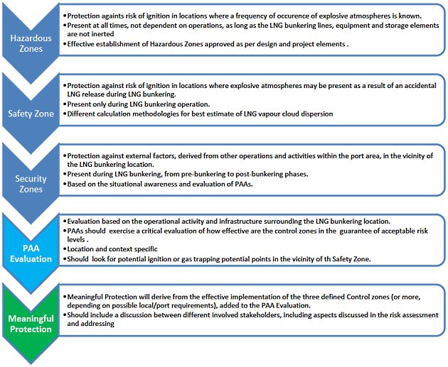
Meaningful Protection
The Concept of Meaningful Protection involves the combination of the all the three above defined Control Zones. It recognizes that only by an effective implementation and control of all control zones it will be possible to achieve Meaningful Protection to the LNG bunkering operation, surrounding populations, infrastructure and activities.
Below, the diagram in figure 1, presents the different control zones, and PAA evaluation, contributing collectively to define meaningful protection during LNG bunkering operation.
The Concept of Meaningful Protection will be especially relevant for the establishment of the Safety Zone, in particular where a given calculated Safety Zone is defined and implemented, including in its vicinity potential ignition elements or locations with significant gas trapping probability.
In fact, regardless the calculation methodology followed for a Safety Zone there is nothing that can replace the on-site judgement of context, operations, ongoing construction works, modifications, amongst other local and time dependent effects that should be judged in conjunction by operators and PAAs prior to LNG bunkering operations.
The main starting point, for the Safety Zone definition, should be the calculation elements, either derived from deterministic or probabilistic methodologies. From the calculations a more or less regular Safety Zone should be determined and approved. Whether this Safety Zone is, in fact, providing meaningful protection against possible hazardous outcomes of an LNG accidental release should however take an additional element into account: the shared judgement of the onsite situational awareness.
Example of application of the Meaningful Protection example:
Figure 2, below, include an example of the application of the Meaningful Protection concept. In “A” it is represented a regular circular shaped Safety Distance, with a radius calculated following any given maximum credible release scenario. It can be seen in the same situation “A” that several elements nearby the bunkering location, yet outside the Safety Zone, are either potential ignition sources or gas trapping points where explosive atmospheres can easily be created following the passage of an LNG dispersing cloud.
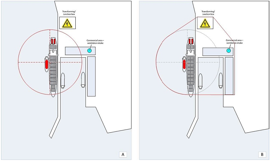
Everything in “A” is according to the existing reference framework for LNG bunkering. The Safety Zone is established according to any of the reference calculation methodologies and the implementation should present no major challenges.
A reading of the surrounding area, just outside the safety zone, identifies a transforming station/junction box, a ventilation intake point for a commercial area and a harbouring basin, in the vicinity, not fully covered by the safety zone.
Together, operators and PAA, determine that notwithstanding the conformity of the Safety Zone, calculated by the relevant applicable methodologies, its implementation should consider the need to include also the above listed elements.
It will be interesting: Maritime Standards Explained. A Focus on EN ISO 20519, ISO/TS 18683, and Supporting Guidelines
In “B” (figure 2) the Safety Zone is expanded on the basis of the understanding between operators and PAA that an increased level of protection would be provided through an adapted modification of the Safety Zone, as calculated, to also incorporate the elements of concern.
Challenges may then result from the implementation of actual protective measures on the Transforming/Junction-Box, ventilation intake or ships at berth in nearby location.
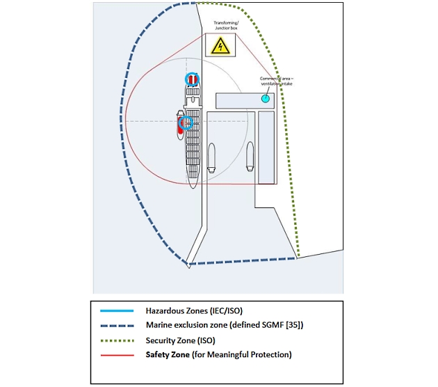
Different ports will of course present different contexts, activities or operational situations which may be well addressed by the Security Area concept, with the monitoring of other nearby activities (see section “Security Zone”). In the example presented in figure 2 the Security Area concept would be deemed potentially insufficient. There would in fact be no risk to the LNG Bunkering operation solely due to the Transforming Station, Ventilation intake or even other ships at berth in nearby location.
Figure 3, below, shows the suggested collective set of control zones to implement in the presented LNG bunkering exampled to STS transfer.
The procedure below is suggested for the confirmation of Safety Zones, respecting the concept for Meaningful Protection and the authorization procedure (section “Approval”):
- Stakeholders identified, with operators and PAA considering all relevant information to confirm the Safety Zone, prior to LNG bunkering operation. Safety Zone as approved in the LNGBMP.
- Indicative flammability range based on published research and LNG vapour dispersion studies (e. g. SGMF, LR, BV, etc.), with consideration for different operating/weather example parameters, and using different computational model sources. (Stakeholders can model the actual situation to provide a more site specific range).
- Reasons/Controls to increase or decrease the dispersion range identified, and investigated with respect to Impact (Supported by expert judgement, dispersion modelling and/or QRA, as appropriate, wrt site operational and weather specifics).
- Proposed Safety Zone informed by 1 and 2.
- Stakeholders discuss and agree on the Safety Zone to be set.
Control Zones in LNG Fuelling
Control Zones in LNG fuelling should follow the exact same principles as in LNG bunkering. The same methodologies are applicable for definition of Hazardous Zones, which are dependent on design elements where the frequency of occurrence of explosive atmospheres is known. As defined in section LNG Bunkering Hazardous Zone: Safety, Classification, and Control“Hazardous Zone”, these elements will include connections, manifolds, venting and PRVs.
The main evident factors which are likely to influence the shape of control zones, when compared to LNG bunkering, are:
- Much lower LNG flow rates transferred to receiving ship, as the evaporator onboard feeds directly a DF generator.
- Longer period of stay, potentially during the whole stay of the ship at berth, providing LNG to DF generator onboard.
Above, (1) is an indicator for a potentially reduced safety zone, corresponding to a very small credible release scenario resulting from an accidental release.
On the other hand (2) above should give indication to an extended Security Zone. With trailer present close to the ship for longer periods the need to account for, control and monitor other operations and activities is reinforced.
Figure 4, to the right, shows the relevant control zones to consider for LNG fuelling operations.

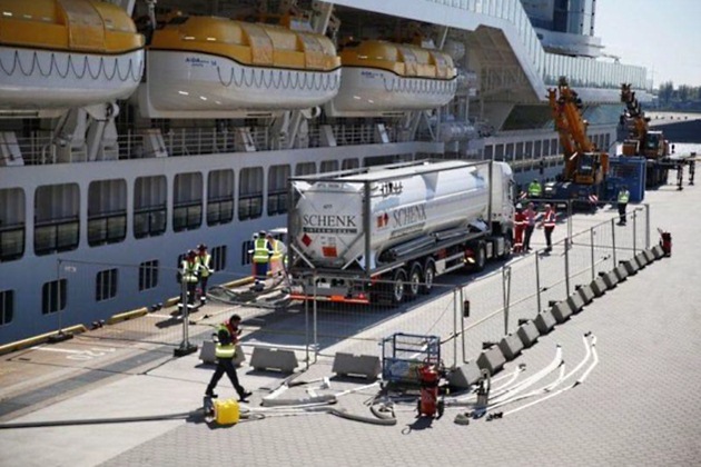
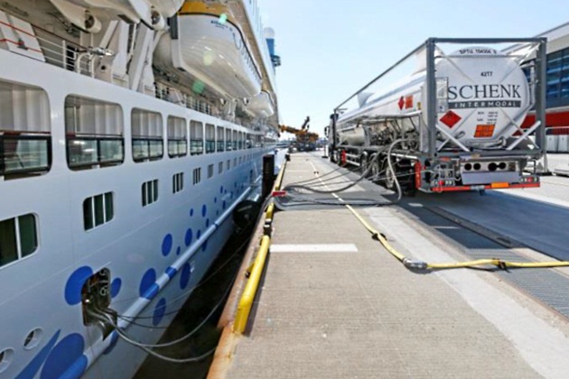
Figures 5, below, represent an LNG fuelling operation, with LNG supplied to a ship from an LNG truck.
Good Practice in Control Zones
The present section summarizes the main good practice elements regarding Control Zones applicable in LNG Bunkering.
Generic First Principles
Control Zones are fundamental principles for Safety in LNG bunkering operations. PAAs should support their evaluation of proposed Safety D Generic first principles that should be observed in all control zones determination:
- Control Zones act as layers of defence – Only working collectively and effectively implemented they will provide the necessary safeguard and risk mitigation.
- There is no hierarchy amongst Control Zones – No control zone is more relevant than the other. They address different risks and only collectively it is possible to ensure safe LNG bunkering operation.
- The Safety Zone must be larger than the Hazardous Zone(s) in all three dimensions.
- The Monitoring and Security Area must be larger than the Safety Zone.
- Hazardous Zones are present at all times, whilst Safety Zones and Monitoring and Security Areas will be present only during Operations.
- The only measure of adequacy for a Safety Zone should be the level of protection granted by its implementation. The different calculation methodologies for Safety zones will only provide estimated flammability extents. There is the need to evaluate the local conditions, infrastructure and ensure that the calculated Safety Distance is adequate for the intended protection.
- Factors affecting the calculation of Safety Distances:
1 Bunkering parameters (pressure, temperature).
2 Potential for excessive BOG generation.
3 Weather factors (in particular wind).
4 Other activities nearby (remarkably those involving also safety distances).
5 Local infrastructure.
6 Receiving ship characteristics.
7 Implemented safeguards, resulting from risk assessment.
- PAAs should have procedures for the evaluation, support in implementation, control and enforcement of Control Zones.
- Controls Zones are only effective if effectively controlled and enforced.
Fixed Safety Distances, established/fixed for ship type (RSO) of LNG bunkering mode (STS, TTS, and PTS) are not recommended. All Safety Zones should be supported by calculations based on assumptions that closely reflect local conditions.
Read also: LNG Regulatory Framework International and European Maritime Safety Overview
In addition to the first principles presented in the previous page, and to the general procedure suggested above, in the diagram of figure 4, the present Guidance Control Zones “minimum requirements” and “meaningful protection” should necessarily be considered together:
a. Minimum requirements will be derived directly from standards, direct/numerical calculations or modelling. References can be given for minimum required control zones and area definition.
b. Meaningful protection is based on the implementation of the minimum requirements, adding to it a critical iterative judgement of the situational scenario, infrastructure and local conditions at the time of LNG bunkering operation. This will be the concept further explored in section “Meaningful Protection”.
The following share of responsibilities should be considered as good practice for the definition, approval and implementation/enforcement of Control Zones:
| Responsibilities in Control Zones | |||||
|---|---|---|---|---|---|
| Calculate/Determine | Plan | Approve | Implement | Control | |
| Hazardous Zone | BFO/RSO | N/A | PAA, for the bunkering interface (Hazardous Zones on the ship side approved as per Ship Certification/Flag approval) | RSO/BFO | PAA |
| Safety Zone | BFO/RSO | BFO/PAA | PAA | BFO, with PAA support | PAA |
| Security Zone | PAA | PAA | PAA (internal approval procedure) | PAA | PAA |
Different arrangements are possible from those in table, above, and may be accepted based on agreement between PAA and operators.
Hazardous Zone
Approval of Hazardous Zones is of the responsibility of the PAA during the evaluation of the project proposal, in the course of the permitting process.
The following elements should be checked for approval of Hazardous Zones by PAAs:
a Identification of all Hazardous Areas in suitable diagrams/plans where the whole LNG bunkering system is represented. Zones 1 and 2 should be clearly identified and related to the following elements in the bunkering system:
i Bunkering manifolds, their flanged connections or containment coamings.
ii Flanged connections along the bunkering line.
iii Venting lines, GCUs.
iv ERC.
v QC/DC bunkering connectors.
vi Any flanged connection along the bunkering transfer system.
vii Bunkering articulated arms, in particular where swivel LNG piping joints are present, mechanical elbows and other articulated connections.
b Identification of the references for each Hazardous Zone presented. One or more of the references below should be presented:
i IEC 60079-10-1, indicating which assumptions were followed for the definition of the Hazardous Zone extent.
ii IGF/IGC Code, making reference to the code, in particular indicating pressure and temperature windows defined for the bunkering. The reasoning behind this note is, in particular, relevant to check compatible physical p-t conditions between LNG delivered and LNG.
iii Other Codes, in particular if national/regional standards have been followed, other than IEC/EN related.
iv CFD, identifying the responsible person for the calculations, the code used, assumptions followed, verification & validation procedures, including convergence of model, mesh refinement location, boundary conditions.
LNG Bunkering Guidelines: Comprehensive Insights and Best Practices for OperatorsLNG Bunkering management Plan, to be checked for reference to Hazardous Zones, in particular provisions for its establishment and control.
Enforcement of Hazardous Zones should be done during in-service inspection of LNG bunkering facilities for Ex-proof confirmation of the whole inventory of electrical equipment used.
To support in this task, PAAs should request to operators a full updatable inventory for Ex-proof equipment, consisting of a list of electrical equipment that can subject to verification/check for Ex-proof conformity. Only electrical equipment contained in that list should be present in operation.
It will be interesting: LNG Bunkering Feasibility: An Analytical Framework
Other potential ignition sources, other than electrical equipment should be looked for.
Upon any finding which may raise concern regarding to insufficient ignition source mitigation, the LNG bunkering operation should be halted until the findings are resolved.
In-service inspections for Control Zone enforcement should be conducted with minimum impact in the planned course for the LNG bunkering operation, not leading to unnecessary undue delays to all operators involved.
Safety Zone
Approval of Safety Zone is of the responsibility of the PAA during Permitting, subject to Confirmation prior to each Operation, at Pre-Bunkering phase:
a Permitting: During presentation of the project/facility for Permitting, where the intended Safety Zones should be specifically indicated in the LNG Bunkering Management Plan. Operators will include the calculation.
b Pre-Bunkering: Prior to LNG bunkering operation, PAA should check consistency with permit approved Safety Zone.
The following elements should be checked for approval of Safety Zones by PAAs:
a Permitting (Approval of Safety Zone):
i Identification of Safety Zone in suitable diagrams/plans where the whole Technical requirements for LNG bunkering systems on shipsLNG bunkering system is represented, including surrounding infrastructure elements. All relevant areas within the proposed Safety Zone should be clearly identified with the indication of points of contact for each area.
Areas in the vicinity of the Safety Zone should also be clearly identified in particular indicating the existence of:
- Hazardous Zones;
- Populated areas;
- Potential Ignition sources;
- or Gas trapping points.
Should different Safety Zones have been approved during Permitting, all should be included in the diagram view, with the reference to the parameters followed.
ii Supporting Report with Calculations for the definition of the Safety Zone. One or more of the references below should be presented:
- Analytical Calculations, based on first principles calculation, following application of relevant mathematical formulation and geometry for dispersion visualization.
- ISO Methodologies, following ISO/TS 18683, or ISO 20519, curves for ISO (a) or (b) methods, with the clear indication of the parameters assumed to read from the curve.
- Computational calculations/CFD, identifying the responsible person for the calculations, the code used, assumptions followed and parameters used for modelling, verification & validation procedures, including convergence of model, with an RMS of less than 1E-5, mesh refinement location, boundary conditions.
iii LNG Bunkering Management Plan, to be checked for reference to Safety Zones, in particular provisions for its establishment and control.
b Pre-Bunkering (Confirmation of Safety Zone):
i Confirmation of LNG bunkering parameters, as indicated in the LNGBMP. Prior to initiation of LNG bunkering operation the Safety Zone must be Confirmed, taking into account the verification of the LNG bunkering parameters, local conditions, potential restrictions and other factors that may have to be accounted for by PAAs, in conjunction with Operators. (RSO and BFO).
ii Safeguards, with the verification that safeguards contributing to the definition of the Safety Zone, possibly defined in a risk assessment, are implemented.
iii Context Evaluation, considering any operational aspects which had not been foreseen during permitting, including any possible construction/maintenance works, temporary modifications.
As per the above it is important to note that a Safety Zone should only be implemented if: Approved and Confirmed. Elements relevant to the Approval should be documented as part of the Permitting/Certification documents. Those relevant to the Confirmation should be part of the Authorization documents, i. e. supported by check-list procedure.
Security Zone
The Security Zone is the responsibility of the PAA, reflecting the situational awareness of the port area in any given moment.
It is suggested as good practice that an internal approval process should be developed by PAAs to ensure that the definition of a Security Zone is a documented procedure of shared responsibility within the PAA.
Source: Unsplash.com
Definition and approval of the Security Zone should be based on the elements provided by the Operators, remarkably on the proposed safety zone.
Read also: LNG Bunkering Guide – What It Is and How to Use It
PAAs should enforce Security Zones by either physical barriers or by communications with all the points of contact/responsible coordinators involved in the port activities to monitor. It is important, more than the guarantee of physical barriers, that all activities are monitored and that communications are established with each different operators to ensure early warning and alarm dissemination in the event of any problems with the bunkering operation.
Meaningful Protection
The procedure below is suggested for the confirmation of Safety Zones, respecting the concept for Meaningful Protection and the authorization procedure (section “Approval”):
a Stakeholders identified, with operators and PAA considering all relevant information to confirm the Safety Zone, prior to LNG bunkering operation. Safety Zone as approved in the LNGBMP.
b Indicative flammability range based on published research and LNG vapour dispersion studies (e. g. SGMF, LR, BV, etc.), with consideration for different operating/weather example parameters, and using different computational model sources. (Stakeholders can model the actual situation to provide a more site specific range).
c Reasons/Controls to increase or decrease the dispersion range identified, and investigated with respect to Impact. (Supported by expert judgement, dispersion modelling and/or QRA, as appropriate, wrt site operational and weather specifics).
d Proposed Safety Zone informed by 1 and 2.
e Stakeholders discuss and agree on the Safety Zone to be set.