Master the process of cargo discharge from LNG carriers with this detailed guide, covering preparation, step-by-step ramp-up and ramp-down procedures, bulk rate discharge, post-discharge operations, and essential considerations for safe and efficient unloading.
- Overview
- Preparation for discharge
- Pre-discharge operations
- Ramp-up to bulk rate
- 4-STEP ramp-up
- 8-STEP ramp-up
- Operational description – bulk rate discharge
- Ramp-down
- Ramp-down “heel retained”
- Operational description – ramp-down “heel out” ( Cargo tank stripping)
- Post-discharge operations
- Departure from discharge port
- Further considerations during discharge
Reference: SIGTTO “LNG Shipping Suggested Competency Standards”, Sections:
1 Have an awareness of cargo discharge principles:
- normal “ramp up” and “ramp down” procedures;
- initiating discharge sequence using automatic and manual controls;
- CTMS – pre and after complete discharge procedures;
- line up of cargo system;
- use of cargo pumps to regulate flow of LNG to shore.
2 Know and understand cargo discharge principles. Cargo heel:
- purpose (retention or heeling out);
- calculate quantity to be retained and formulate issues to be considered;
- possibilities regarding location of retained cargo and possible disadvantages and advantages of each.
3 Know and understand cargo discharge procedures:
- vapour pressure control:
- vapour supply from shore;
- vapour supply from ship: LNG vaporiser operation and control in order to maintain required vapour supply;
- tank pressure requirements during discharge and the reasons why they should be maintained.
- parameters that should be monitored throughout operation and formulate criteria that may indicate problems;
- procedure to:
- retain defined quantity of heel on board;
- ensure maximum quantity of liquid discharged.
- stripping of cargo tanks;
- valve conditions on completion of discharge.
4 Know ballasting procedures:
- ballast procedure to be implemented to maintain required draught and trim requirements during discharge;
- ballast pumps and eductor operation.
Overview
During a normal discharge, only the main cargo pumps will be used and a quantity of cargo will be retained on board for conditioning the cargo tanks. The quantity of LNG to be retained is determined by the duration of the ballast voyage.
If the ship has to warm up tanks for technical reasons, the stripping/spray pumps will be used to discharge the remaining cargo on completion of bulk discharge with the main cargo pumps. During cargo discharge, LNG vapour is supplied from shore to maintain pressure in the cargo tanks.
Should the vapour return supply from shore be insufficient to maintain tank pressures, other means of supplying vapour to the tanks must be used. This can be achieved using sprayers or an Use of Vaporisers on Liquefied Natural Gas CarriersLNG vaporiser.
Ballasting is undertaken at the same time as discharging. The ballasting operation is planned to keep the ship within the required limit of draught, trim, hull stress and stability following indications obtained from the loading calculator.
During the discharge period, the ship is trimmed slightly by the stern. If it is required to empty a cargo tank, the ship is trimmed according to terminal maximum draught by the stern, to assist in the stripping of the tank.
Depending on the cargo plan, each tank may be discharged down to a minimum level (minimum level attained by main cargo pumps) in tanks other than the heel tank. This is normally the smallest tank as it gives a greater suction head for the spray pump.
Preparation for discharge
Preparation for discharge will generally be similar to preparation for cargo loading.
Three or four days prior to arrival at the terminal:
- ensure that a cargo discharging and ballasting plan is available;
- conduct a cargo valve (including vent mast) functionality test;
- conduct a ballast system valve functionality test;
- all portable and personal gas detectors are tested and calibrated;
- all certification lead seals on cargo tank gauges confirmed as intact;
- availability of mooring lines, pennants and winches as required;
- checking and Comprehensive Guide to Ship and Shore Preparation and Manifold Connection for LNG Cargo Operationsfitting of manifold short distance (spool) pieces, filters, gaskets and presentation flanges;
- pressure test the liquid and vapour manifolds with N2. Test pressures should be 5 bars at the liquid manifold and 2 bars at the vapour manifold. Use soapy water to detect for leaks.
Two days prior to arrival at the terminal:
- the ESDS is tested and proved fully operational within 48 hours of arrival in port, including emergency stops for cargo pumps;
- confirm that all remotely operated valves have been checked and are confirmed to be within surge avoidance parameters;
- set the cargo system and ensure that the intended offshore manifold is secured.
Confirm the following are available prior to cargo operations:
- cargo tank pressure control systems (GCU, reliquefaction plant, fuel gas where fitted);
- independent cargo tank high-level alarm system;
- manifold water curtain;
- fire pump/water spray system and all other fire-fighting equipment confirmed as available;
- gas detection and fire detection equipment;
- check that cargo pumps starting interlocks are cleared with the correct line up;
- the Master confirms to the terminal the functionality of the cargo and ballast systems;
- all deck lighting;
- pilot boarding arrangements – test/rig/prepare as appropriate.
One day prior to arrival at the terminal:
- pre-arrival meeting (including finalisation of the appropriate risk assessments);
- ensure the LNGC is prepared as per the approved ship/shore compatibility study, including manifold connections and mooring layout;
- ensure new gaskets are fitted/available for all manifold related connections;
- mooring lines are laid out and appropriate tails fitted;
- cargo/spray pump motors and associated transmission cables are in good order (check the insulation resistance to earth);
- where the discharge terminal has requested that the LNGC arrives with the liquid header cooled down, this can be done the day before arrival and then topped up on the day of arrival.
Day of arrival at the terminal:
- adjust the cargo tank pressures as per terminal requirements;
- adjust ballast for appropriate arrival draught and trim;
- ensure that all deck scuppers are closed;
- ensure that all deck savealls are dry and clean;
- prepare stainless steel buckets filled with fresh water at cargo tank domes;
- provide an adequate supply of fresh clean rags for use as a temporary method to stem a minor leak;
- prepare the SOPEP equipment;
- prepare deck fire-fighting equipment;
- prepare the international ship/shore fire connection.
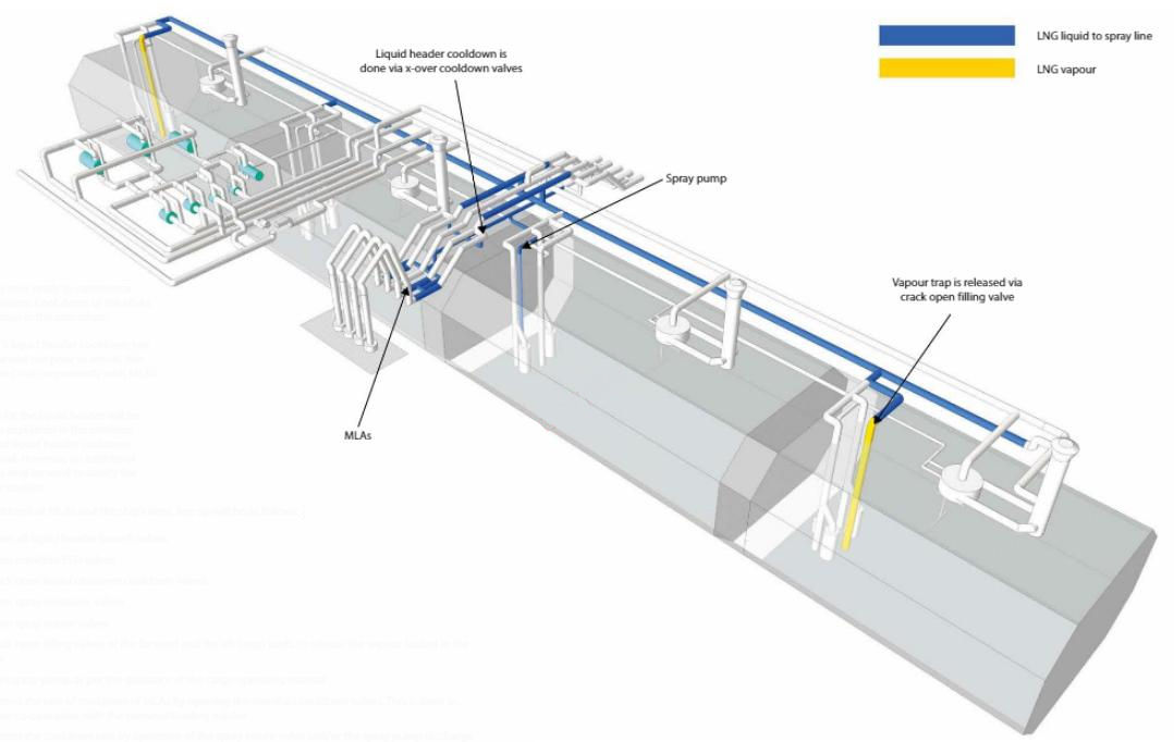
Liquid header cooldown prior to arrival
This operation will generate additional BOG and increase the tank pressure. It can be carried out one day before arrival, allowing the gas management system to handle the additional BOG. On arrival day, only top-up will be required.
An LNGC with a Liquefied Natural Gas Reliquefaction Plantreliquefaction plant has the facility to utilise condensate return for this purpose. It should be noted that condensate return will have significantly smaller flow capacity than the spray pump and, if used for cooldown, the operation will take longer to complete.
LNGCs will generally use the spray pump for the liquid header cool down and the operation is typically as follows:
- open all liquid header branch valves;
- verify that all manifold ESD and double-shut valves are closed;
- open liquid crossover cooldown valves;
- open spray crossover valves;
- open spray return valves;
- crack open the filling valves of the forward and the aft cargo tanks to release the vapour locked in the line;
- start spray pump as per the cargo operating manual;
- ensure even cooldown of the liquid header by adjusting the filling valves of the forward and aft cargo tanks;
- control the cooldown rate by operating the spray return valve and/or spray pump discharge valve;
- when liquid crossover and liquid header are fully cooled and showing signs of frosting, crack open the cargo pump discharge valves to cool down pump discharge columns and valves.
The operation is considered completed when the temperature probes on the liquid header are showing values prescribed in the cargo operating manual.
On arrival – considerations for all LNGCs:
- the main engine(s) must be isolated (but not immobilised) prior to receiving the gangway;
- in the CCR, set the cargo tank level alarms to the “in port”/”harbour” condition.
Pre-discharge operations
- Inhibit (block) the ESDS;
- connect the communication/ESD cable, usually a male/female plug arrangement (fibreoptic or electrical) that provides the various channels for ship/shore communication and ESD interconnection;
- the ESD block will remain in place until the completion of connection of MLAs and the point at which the system is proven healthy;
- where utilised, connect the ESD umbilical cable, which is usually a pneumatic connection;
- ensure that ship/shore communication systems are established and proved operational. These include the mooring tension monitor, hot-line and plant phone;
- while ISGOTT does not recommend the use of a ship/shore bonding cable, some terminals still insist on such a connection. The ship/shore bonding cable should be checked to ensure it is mechanically sound and connected clear of the manifold area.
The usual arrangement at most Dynamic Simulation and Optimization of LNG Plants and Import TerminalsLNG import terminals is three liquid MLAs and one vapour MLA. Operations are as follows:
- the terminal will require the ESD manifold valves to be closed and blocked and the double-shut valves to be closed before the MLAs are connected;
- when the MLAs have been connected, they are purged with N2 until the O2 level is < 1 % by volume.
- once the MLAs have been confirmed as having an O2 level < 1 % by volume, they are pressurised with N2 to a pressure of 5 bar in each liquid arm and 2 bar in the vapour arm;
- the responsible ship’s officer and terminal representative check all associated joints for leakage;
- when the MLAs have been proven free of leaks, they are depressurised in a controlled manner;
- all cargo tank level alarms are confirmed as operational;
- the LNGC is confirmed as being upright and on an even keel;
- the opening custody transfer measurement (CTMS) should be conducted. Ensure the CTMS is conducted in the presence of the Chief Officer, loading master and any cargo surveyor (if appointed);
- the manifold water curtain must be started as soon as the MLAs are connected;
- the Ship/Shore Safety Checklist and the ISPS checklist should be completed;
- when the LNGC and terminal are ready to carry out ESD tests, it should be confirmed whether it is the LNGC or the terminal that will initiate the shut down;
- a warm test of ESD should be carried out with pipelines and valves at ambient temperature.
Note: the N2 is typically supplied by the terminal, however, there are certain terminals that will request that the LNGC supplies the N2 for purging and pressure test of the MLAs.
Once ship and shore have confirmed correct ESD operation, the system must be reset and confirmed as healthy. The appropriate valves (manifold/ESD) may now be re-opened, There must be a double-check and confirmation of the cargo system line up.
Ensure all inhibited alarms are returned to normal by the Chief Officer, in the presence of the Master.
The LNGC is now ready to commence cargo operations. Cool down of the MLAs is the next step in the procedure.
If the LNGCs liquid header cooldown has not been earned out prior to arrival, this can be earned out concurrently with MLAs cooldown.
The line up for the liquid header will be the same as explained in the previous procedure of liquid header cooldown prior to arrival. However, an additional spray pump may be used to satisfy the demand for coolant.
For the cooldown of MLAs and the ship’s lines, line up will be as follows:
- open all liquid header branch valves;
- open manifold ESD valves;
- crack open liquid crossover cooldown valves;
- open spray crossover valves;
- open spray return valves;
- crack open filling valves of the forward and the aft cargo tanks to release the vapour locked in the line;
- start spray pump as per the guidance of the cargo operating manual;
- control the rate of cooldown of MLAs by opening the manifold cooldown valves. This is done in close co-operation with the terminal/loading master;
- control the cooldown rate by operation of the spray return valve and/or the spray pump discharge valve;
- when the liquid crossover and the liquid header are showing signs of frosting, crack open the cargo pump discharge valves to cool down pump discharge columns and valves;
- the operation is considered completed when the temperature probes on the liquid header are showing temperatures as prescribed in the cargo operating manual;
- the terminal will advise readiness of their lines.
Note: some LNGCs are fitted with manual valves connecting liquid and spray headers at the forward and aft cargo tank liquid domes. In such an arrangement, one spray pump can be utilised for cooldown of the MLAs and another pump utilised for liquid header cooldown. Both operations would run concurrently but separately.
Ramp-up to bulk rate
A cold Emergency Shutdown System (ESDS) on Liquefied Gas CarriersESD test or valve function test is carried out on completion of cooldown to verify the correct operation of the manifold valves when they are in a cold state. The reset procedure should then be followed.
The ramp-up procedure is usually as follows:
- prior to starting the first cargo pump, line up,the cargo system for discharging and ensure that the line up has been independently checked by two officers;
- with the terminal’s permission, open the manifold ESD valves;
- request terminal permission to start the cargo pump and inform the E/R.
The ramp-up is carried out sequentially, as agreed with the terminal in the pre-discharge meeting. Some terminals will have specific procedures requesting particular rates at different stages of the ramp-up. Generally, if no other specific procedure is agreed, there are two methods for ramp-up, one involving 4 steps and the other 8 steps.
Note: Procedures explained here refer to an LNGC with four cargo tanks.
The maximum discharge rate will be agreed in the pre-discharge meeting. The ship can either discharge with the rated flow of all cargo pumps or with a designated maximum continuous rate.
Cargo tanks are not equal in volume and the volume of the No. 1 cargo tank is usually half that of the largest tank. The time required to discharge the largest tank with two cargo pumps at the rated flow will be the bulk discharge time. This value is then applied to the other tanks to estimate the required discharge rate per tank. The sum of the discharge rates in each tank, calculated by this method, will give the maximum continuous discharge rate.
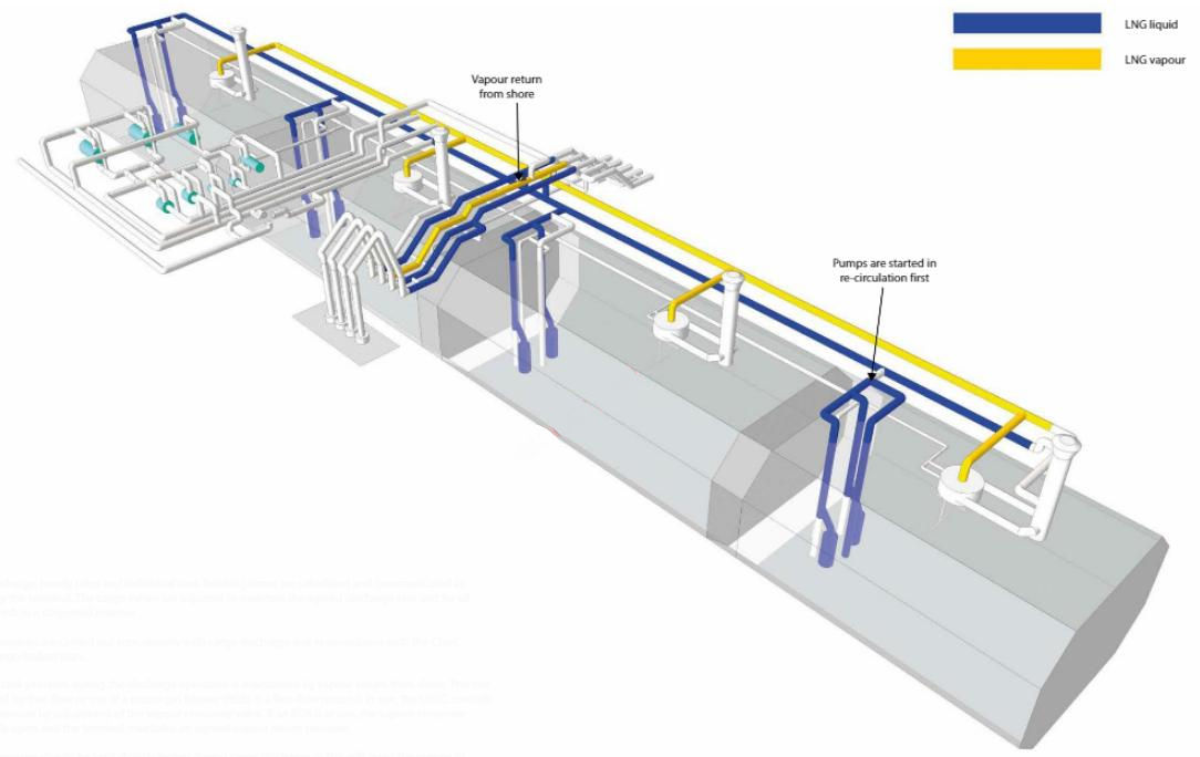
4-STEP ramp-up
The ramp-up method, where both cargo pumps in one tank are started in recirculation before discharging has commenced, is known as a 4-step method.
The procedure for a 4-step ramp-up to bulk discharge rate (on an LNGC with 4 tanks), where 2 pumps in each tank are started before discharging to shore, will be as follows:
- close the cargo tank branch valve;
- open the cargo tank filling valve;
- open the 1st cargo pump discharge valve to the recommended starting position;
- start the 1st cargo pump in recirculation and adjust the flow slightly above the minimum;
- open the 2nd pump discharge valve to the recommended starting position;
- start the 2nd cargo pump in recirculation and adjust the flow slightly above the minimum;
- commence opening the cargo tank branch valve;
- when the branch valve reaches 30 %, commence closing the filling valve;
- when the branch valve is fully open and the filling valve is fully closed, discharging has commenced;
- repeated procedure for the remaining tanks;
- once all cargo pumps are running, rate is increased to the maximum rate as agreed in the pre-discharge meeting.
Note: ramp-up is a critical stage of the discharge operation. At this point, cargo tanks are full and even a minor error in valve operation can potentially lead to cargo tank overflow. For that reason, it is essential that tank protection/overflow protection is active during the discharging operation. This is particularly the case with 4-step ramp-up, where discharging is in progress from 3 cargo tanks before the last cargo tank is online. At that moment, when the operator is changing over the branch and filling valve, an increasing cargo tank level may be observed. This will be no reason for concern if valves are operated correctly as it will take a short time until the filling valve is fully closed. It recommended that an officer is on deck to visually confirm the valve position during ramp-up. This operation must be executed with extreme caution.
8-STEP ramp-up
This ramp-up method is where the 1st cargo pump in each cargo tank is started in recirculation and the 2nd cargo pump is started online. This method is much safer when tank overflow is a concern.
The procedure for an 8-step ramp-up to bulk discharge rate (on an LNGC with 4 tanks), where 1 pump in each tank is started before discharging to shore, will be as follows:
- close the cargo tank branch valve;
- open the cargo tank filling valve;
- open the 1st cargo pump discharge valve to the recommended starting position;
- start the 1st cargo pump in recirculation and adjust the flow slightly above the minimum;
- commence opening the cargo tank branch valve;
- when the branch valve reaches 30 %, commence closing the filling valve;
- when the branch valve is fully open and the filling valve is fully closed, discharging has commenced;
- repeat the same procedure for the remaining cargo tanks;
- when one cargo pump is running in each cargo tank, proceed to start the remaining cargo pumps without recirculation.
Whichever method is used for ramp-up, there is another practice that may have to be taken into consideration when starting the cargo pumps. Usually, each LNGC will have the cargo pumps’ power supply arrangement provided in two separate switchboards. Each switchboard will have a soft starter that is common to all cargo pumps for the switchboard.
Where possible, never start two pumps from the same switchboard, one after another. If the 1st cargo pump that has been started is connected to the port switchboard, then the second cargo pump should be started from the starboard switchboard. The remaining cargo pumps should then be started by continually alternating the switchboards. Some LNGCs may be fitted with an interlock at the soft starter, disabling the permission to start function until sufficient time has elapsed between starting cargo pumps
Operational description – bulk rate discharge
During discharge, hourly rates and individual tank finishing times are calculated and communicated as required by the terminal, The cargo valves are adjusted to maintain the agreed discharge rate and for all tanks to finish in a staggered manner.
Ballast operations are carried out concurrently with cargo discharge and in accordance with the Chief Officer’s cargo/ballast plan.
The tank pressure should be kept slightly higher during cargo discharge as this will assist the pumps in maintaining the suction head (typically 12-14 kPa).
Prior to commencing ramp-down the vapour return from shore is adjusted. This allows the tank pressure to reduce before the end of cargo operations as when cargo tanks are nearly empty, there will be no great effect from the cargo pumps on tank pressure. Note that not all terminals have sufficient vapour return How so, on occasion, an LNG vaporiser may need to be used by the LNGC.
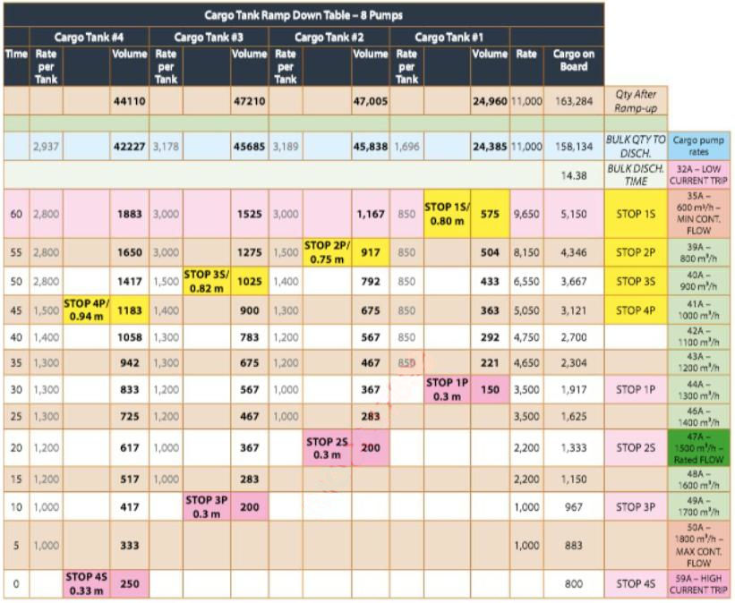
Ramp-down
One hour prior to ramp-down, inform the E/R. As the suction head reduces on the pumps in each tank, adjust the discharge valve to maintain back pressure and ampere load above the associated tripping levels.
Before stopping a cargo pump, throttle-in the discharge valve. Where two main cargo pumps are in use in a tank and the level reaches an approved predetermined level (typically 0,8 to 0,6 m – this value will depend on cargo pump design), throttle-in the discharge valve on one pump and then stop that pump. This action reduces turbulence around the pump suctions as the suction head is reduced.
Read also: Custody Transfer Measurement System (CTMS) on Liquefied Gas Carriers
Depending on the heel retention requirements, as the predetermined (minimum) level is approached in each tank, stop the main cargo pumps in each tank and close the associated discharge valves.
When all cargo pumps have been stopped, discharge valves are closed and the discharge has been confirmed as complete, the terminal will request closure of the manifold double-shut valves. The double-shut valves will then be line purged with N2, with branch valves and filling valves open. After draining and line purging, the terminal will request the ESDS to be inhibited before disconnecting the MLAs.
Ramp-down “heel retained”
The ramp-down procedure is straightforward if heel is retained for the ballast passage as discharge will usually be carried out by main cargo pumps without the use of spray (stripping) pumps. Except for the cargo tank with the required heel for the ballast passage, cargo tanks are discharged to the minimum level attainable by the cargo pump.
The ramp-down is always planned to ensure a staggered stop between each pump as the minimum level is approached.
Operational description – ramp-down “heel out” ( Cargo tank stripping)
The ramp-down “heel out” operation is carried out in preparation for gas freeing prior to dry-dock or as per charterers’ instructions to discharge maximum cargo. The procedure is as follows:
- spray pumps are started in recirculation in each cargo tank in advance of stopping the main cargo pumps (at the level of approximately 1 m each cargo tank);
- the spray piping of each cargo tank is kept isolated from the spray header;
- with the spray pumps in recirculation, the operator can focus on the stripping with the main cargo pumps;
- discharging with the main pumps is done in the normal manner, but the last cargo pump in each tank is kept running until the minimum pump-down level is reached;
- trim by the stern (approximately 3 m) and carefully operate the discharge valve;
- commence stripping cargo tanks with the spray pumps;
- one by one, bring the spray pumps online to avoid fluctuations in pressure by operating the manual isolating valve while monitoring pump performance;
- once all spray pumps are online, keep them running with a minimum flow;
- as the last cargo pump in each cargo tank is stopped, continually monitor the discharge pressure and pump amps of the spray pump;
- complete the cargo discharge operation with the spray pump in the same manner as with the main cargo pumps.
Note: the closing CTMS procedure will determine the stripping operation. For commercial reasons, the liquid level in a cargo tank after this operation must be gaugeable. If closing CTMS is done on an “even keel” then sufficient liquid must remain in the tanks, allowing the use of the primary gauging system. If stripping with the main cargo pumps is done at 3 m trim, and the closing CTMS must be done on even keel, spray pumps not be required.
Post-discharge operations
These are as follows:
- ensure the LNGC is upright and if required, on an even keel;
- on completion of discharge, line up and conduct line drainage;
- on completion of draining, and with the terminal’s permission, close the liquid manifold/ESD valves;
- when satisfied that the BOG management system is controlling the cargo tank pressures, inform the terminal and close the vapour return;
- the loading master will request the terminal to purge the MLAs with N2.
- the closing CTMS is conducted in the presence of the Chief Officer, loading master and/or cargo surveyor;
- the MLAs are disconnected after final depressurisation.
Note: This procedure purges the MLAs of hydrocarbons. The actual method will vary according to the terminal and LNGC type, but whichever method is used, the principle remains the same. Purging will continue in the approved manner until the CH4 content is reduced to less than 1 % by volume.
Departure from discharge port
Prior to departure from the discharge port:
- securely stow float level gauges, where appropriate;
- the Master/Chief Officer completes and issues all relevant paperwork;
- secure and blank the manifold connections;
- with the terminal’s permission, the ship/shore communication cables are disconnected and returned ashore;
- stop the manifold water curtain;
- when all shore personnel have disembarked from the LNGC, remove the gangway;
- in the CCR, set the cargo tank level alarms for sea-going condition.
Further considerations during discharge
It is important that a cargo pump is never allowed to run dry, even for a short period, as this will cause pump failure. A momentary loss of priming during cargo stripping should not be considered the same as running a pump dry. Short operation of the pump with dry suction, but with fluid in the discharge pipe, will not damage the pump or the motor.
As good practice, a cargo pump should never be allowed to trip and should be stopped in a controlled manner. Carefully monitor the discharge pressure and pump amps and stop the pump once significant fluctuation is observed.
When a discharge valve of any cargo pump is operated, this action will affect the operation of all other pumps discharging to the same liquid header. This is particularly important when stopping pumps as the suction head of the pumps is low and fluctuation may cause a pump trip.

- The international group of liquefied natural gas importers (GIIGNL). LNG custody transfer handbook / 6th Edition: 2020-2021.
- ©Witherby Publishing Group Ltd. LNG Shipping Knowledge / 3rd Edition: 2008-2020.
- CBS Publishers & Distributors Pvt Ltd. Design of LPG and LNG Jetties with Navigation and Risk Analysis / 4th Edition.
- NATURAL GAS PROCESSING & ITS ENERGY TRANSITION ROLE: LNG, CNG, LPG & NGL Paperback – Large Print, November 14, 2023.
- OCIMF, ICS, SIGTTO & CDI. Ship to Ship Transfer Guide for Petroleum, Chemicals and Liquefied Gases / 1st Edition, 2013.
- The Society of International Gas Tanker and Terminal Operators (SIGTTO). Ship/Shore Interface / 1st Edition, 2018.