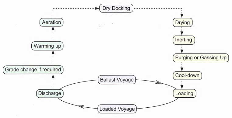
The sequence of operations for Liquefied Natural Gas and Liquefied Petroleum Gas Carriers have certain similarities, however this article will discuss the operations for LPG Carriers, with LNG Carriers covered in Essential Operations with Gas for a Modern LNG Carriers in Typical Trading Cycle“Typical Operations with Gas for a Modern LNG Carrier”.
- Drying
- Older Methods of Drying Tanks
- Current Drying Methods
- Inerting
- Inerting the Cargo System
- Inerting by Displacement
- Inerting by Dilution
- Gassing up
- Gassing-up at Sea Using Liquid from Deck Storage Tanks
- Gassing-up Alongside
- Cool-down
- Loading
- Tank Filling Level
- Topping-off Tanks
- Operation of the Reliquefaction Plant
- Sampling
- Loaded Passage
- Discharge
- Discharge by Deep Well or Submersible Pumps
- Discharge Using Booster Pumps and Cargo Heater
- Discharge by Vapour Pressure
- Ballast Passage
- Changing Grades/Gas Freeing
- Liquid Freeing
- Purging
- Water Washing after Ammonia Cargoes
- Aeration of Cargo Tanks
- Important Points when Changing LPG Cargoes
- From Ammonia to LPG
- From LPG to Ammonia
- To change between: Butane, Butene, Butadiene, Propane, Propene
- Previous Butadiene Cargo
- From Butane to Propane or vice versa
- Tank Cleaning Table Liquefied Gas
The following stages are described as if the ship is entering service from either the ship yard or dry-dock:
- Drying, which is the removal of moisture from the cargo tanks, pipework, etc, to reduce the dew point and minimise ice formation problems;
- Inerting, where oxygen content in the cargo system is reduced to prevent the creation of Flammability, Explosion and other Hazards of Liquefied Gasflammable atmospheres;
- Purging/gassing up to replace inert gas in the cargo tanks, pipes, etc., with vapour of the cargo to be loaded;
- Cool-down of the cargo tank prior to loading to minimise thermal stresses;
- Loading;
- Loaded passage;
- Discharge, which may involve warming- up refrigerated cargoes for discharge into pressurised storage;
- Changing grades, which occurs more frequently in specialist small volume trades or the spot market;
- Warming up and aeration, which is required before dry docking/tank entry/grade changes.
Reminder of the relative vapour densities:
- Methane: 0,054 Lighter;
- Ammonia: 0,597;
- Nitrogen: 0,967;
- Air: 1;
- Inert Gas: 1,05;
- LPG: 1,73 Heavier.
Drying
For any gas carrier it is important to thoroughly dry all the cargo tanks before liquefied gases are carried.
This amount does not include any free water in the cargo tanks that may have been left from the construction or repair yard. Water vapour, if not removed, can cause considerable problems of icing and hydrate formation throughout the system.
Older Methods of Drying Tanks
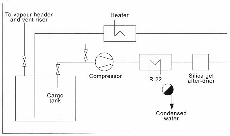
Previously, drying was achieved by means of an air drier. Air from the cargo tanks was removed by a blower, or compressor, and then passed to a refrigerated drier that was cooled by a refrigerant gas. In this unit, the air was cooled and any water vapour condensed out and drained-off. The air that left the drier was saturated al a lower dew point. Further reduction of the dew point was achieved by silica gel drying. After this, the air was warmed back to ambient temperature by an air heater and then returned to the cargo tank. This process continued for all the tanks and pipework system until the dew point of the air was lower than the carriage temperature.
Current Drying Methods
Drying is carried out simultaneously with the inerting operation using the inert gas generator on board. This is normally fitted with both refrigerated and silica gel drying facilities to achieve dew points of -40 °C at atmospheric pressure.
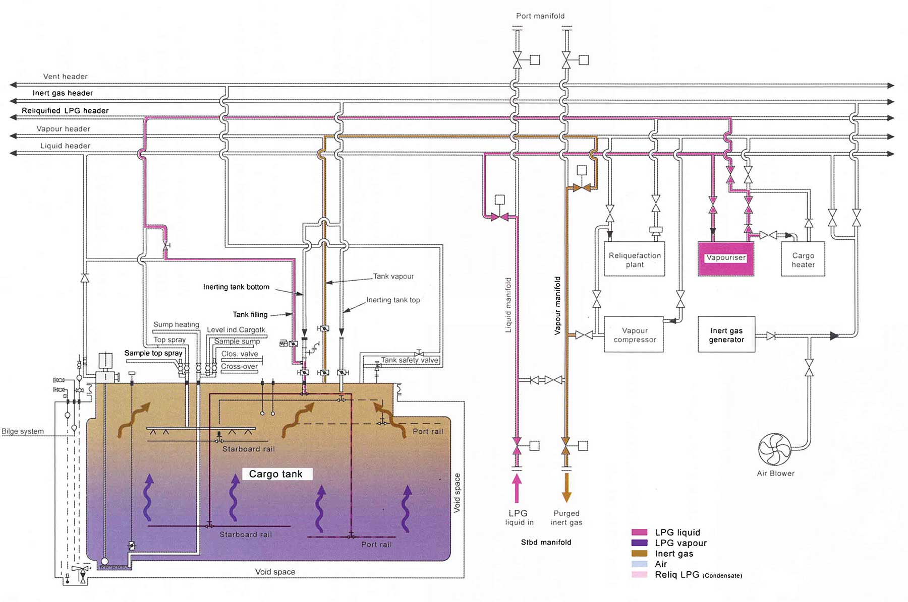
Inerting
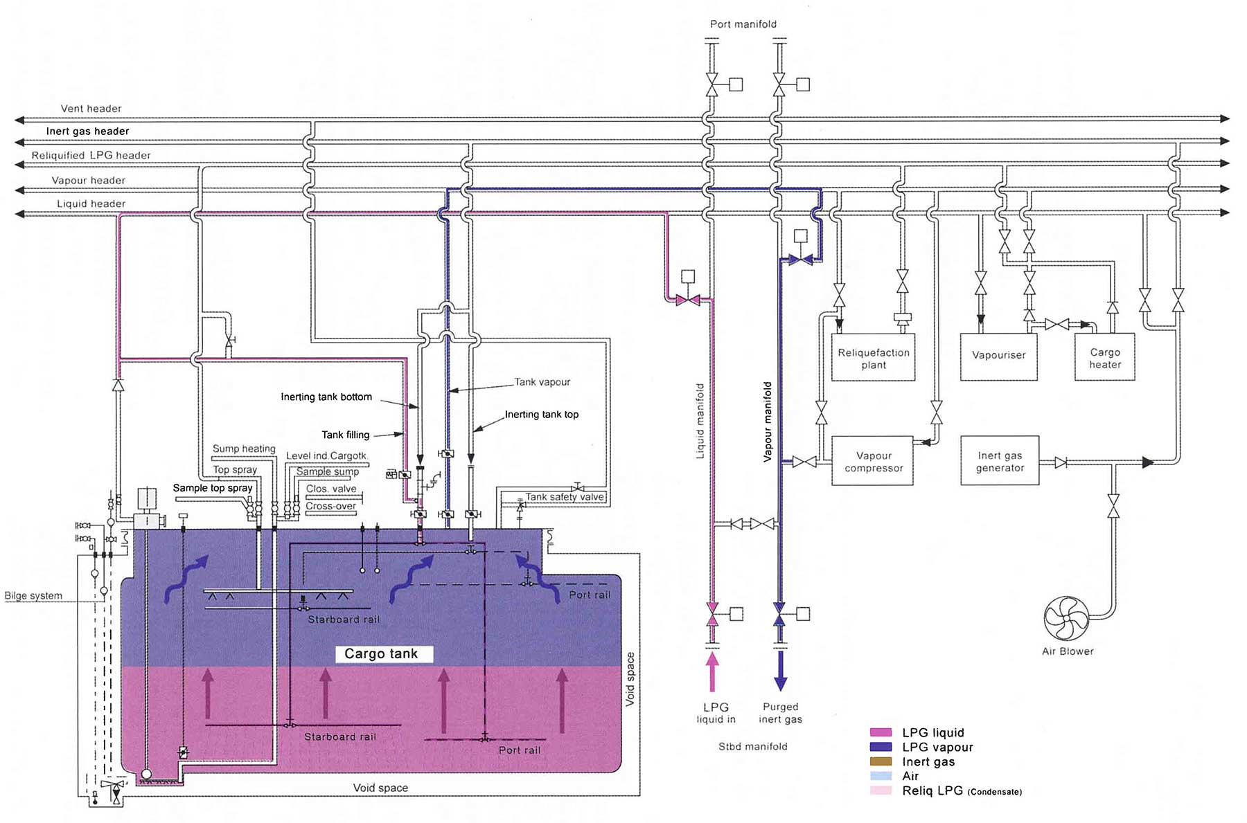
Inerting the Cargo System
Primary inerting of the cargo tanks, pipework system and void spaces reduces the oxygen content to an appropriate level for the cargo to be loaded. For LPG cargoes, 2 % oxygen by volume is considered adequate, while some of the chemical gases, such as VCM and butadiene, may require an oxygen content as low as 0,1 % by volume. There are two methods used for inerting cargo tanks, displacement or dilution.
Some terminals will not accept a vessel where the previous cargo was butadiene unless the ship’s tanks and associated pipework have been purged with nitrogen to ensure a butadiene level of 1 ppm or less.
Inerting by Displacement
Inerting by displacement relies on stratification caused by differences in the vapour density between the gas entering the tanks and the gas already in.

If perfect stratification (interface) was achieved, with no mixing at the interface, then one tank volume of the incoming inert gas would completely displace the air.
If a perfect displacement was achieved, one tank volume of the incoming inert gas would completely displace the air.
In practice, mixing does occur and it will be necessary to use more than one tank volume of inert gas. With primary inerting there is little density difference between air and inert gas (inert gas being slightly heavier).
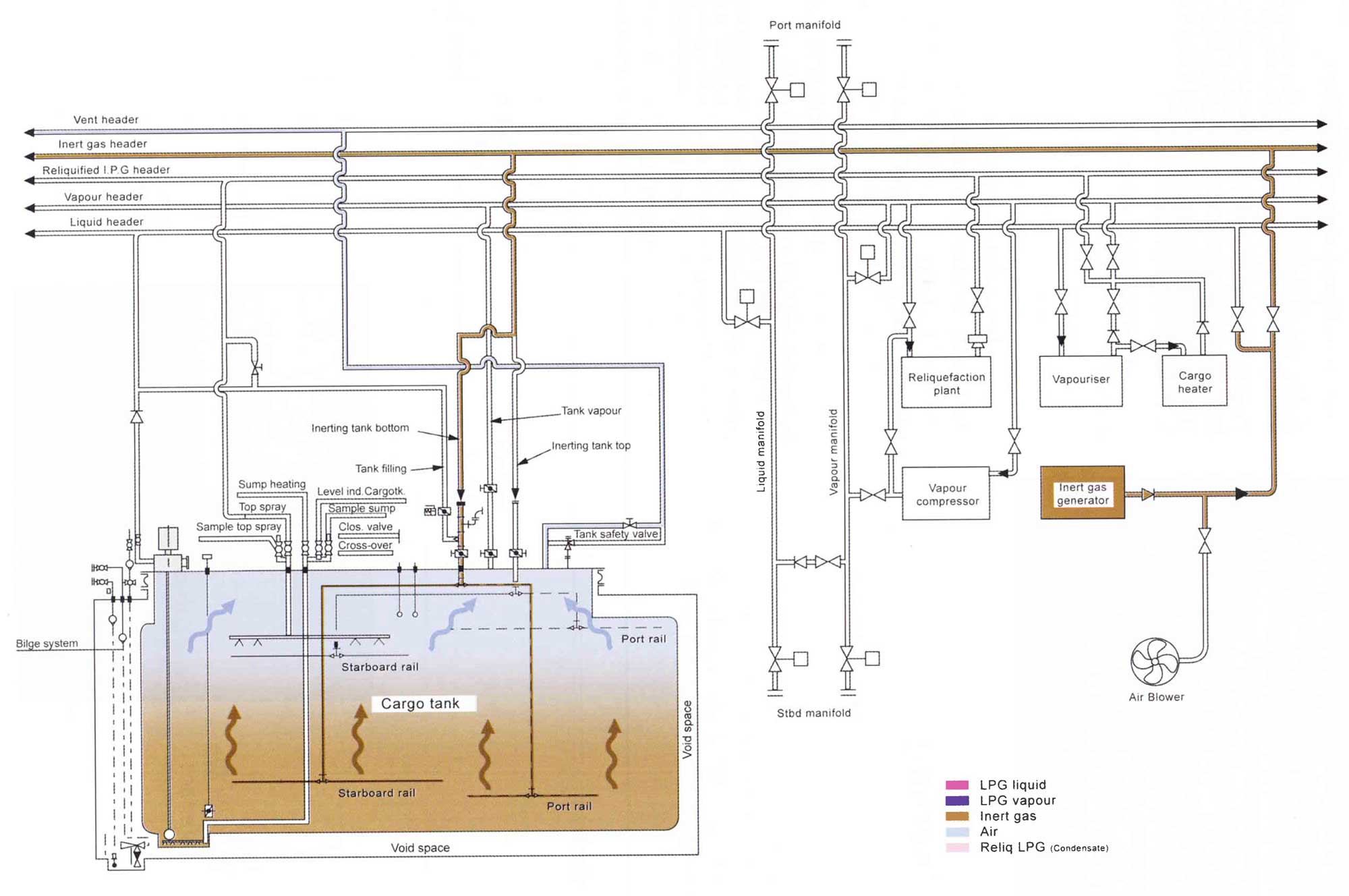
This makes inerting solely by displacement difficult to achieve and so the process often becomes part displacement, part dilution. For primary inerting, the inert gas can be taken through the liquid loading line to the bottom of the tank with the air/inert gas being removed from the tank, via the vapour line, into the vent header.
Inerting by Dilution
In the dilution method, the incoming gas mixes with the gas already in the tank. Dilution can be carried out in several ways:
1 Dilution by Pressurisation
For vessels with pressurised type “C” tanks, dilution can be achieved by pressurising the tank. As an example, for a tank that has its relief valves set at 5 bar, four tank volumes of inert gas from the generator could be introduced into the tank using a cargo compressor, raising the tank pressure from atmospheric pressure to 4 barg (bar gauge – relative pressure).
Dilution is the free mixing of the incoming gas with the gas already in the tank.
The pressure in the tank is then released by opening the vapour line to the mast riser; reducing the concentration of oxygen in the tank to one fifth of its original volume, i. e. 20,9÷5 = 4.18 %.
Using this same technique with 4 tank volumes of inert gas, instead of introducing all of the inert gas to raise the pressure to 4 barg, the inert gas can be used to raise the tank pressure four times to 1 barg, each time achieving a 50 % reduction in the oxygen concentration. Theoretically, the net result would be a reduction to ½×½×½×½ = 6,25 % of its original value, i. e. 20,9×6,25 % = 1,31 %.
Adding 1 tank volume to the tank at atmospheric pressure (0 barg) will double the pressure from 1 to 2 atm – 1 barg.
Similarly, the pressure in the tank could be raised 8 times to 0,5 barg only using 4 tank volumes of inert gas. The reduction in oxygen concentration would then be to (2/3)8 = 3,9 % of its original value, i. e. 20,9×3,9 % = 0,81 %.
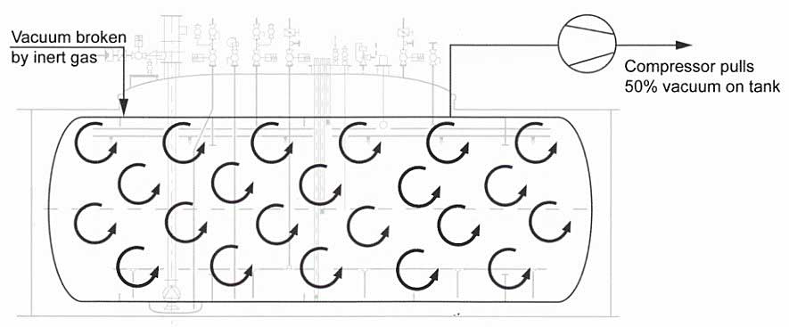
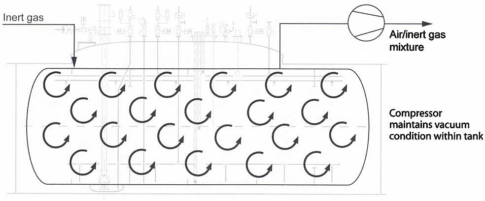
2 Dilution Under Vacuum
Type “C” tanks, on a typical semi-pressurised ship, are generally capable of withstanding a 50 % vacuum.
A typical semi-pressurised ship with type “C” tanks is generally capable of withstanding a 50 % vacuum.
On this type of ship dilution under vacuum can be carried out, using a compressor, to pull a 50 % vacuum on the tank and then breaking this vacuum by the introduction of inert gas. With four tank volumes of inert gas this operation could be repeated 8 times, reducing the oxygen concentration to 0,39 % of its original volume i. e. 20,9×0,39 % = 0,08 %.
3 Continuous Dilution
Dilutions under pressure or vacuum are carried out in stages. However, dilution can also be carried out in a continuous manner, keeping the tank at a constant pressure, by equalising the inlet and outlet vapour flow rates.
In the case of a semi-pressurised ship with Type “C” tanks, continuous dilution can be carried out while maintaining the tank at 50 % through the use of a cargo compressor.
Read also: Types, Layouts and Designs of the Liquefied Gas Carriers (LNG/LPG)
Inert gas can be used in different ways to inert cargo tanks. The most efficient method of dilution is continuously under vacuum, which results in the maximum reduction of oxygen while using minimum quantities of inert gas. However, time may not always allow this method to be carried out and pressurisation may have to be adopted as a means of more quickly achieving an acceptable oxygen concentration, albeit with the use of more inert gas.
A further reduction in the amount of inert gas used to inert a vessel can be achieved by inerting cargo tanks in series, i. e. the gas from one tank taken into the next. This is known as “cascading” (see Picture 6) and it provides another means of inerting cargo pipelines and equipment, although care must be taken to ensure that no contamination is passed over from one tank to the next.
A semi-pressurised ship, whose tanks are designed for 50 % vacuum, may be expected to arrive alongside the loading terminal with her tanks inerted and under vacuum.
While much of this article deals with the use of the inert gas plant, the same principles apply when using nitrogen where, with the exception of ammonia, chemical gases are to be carried, e. g. VCM, butadene, ethylene.
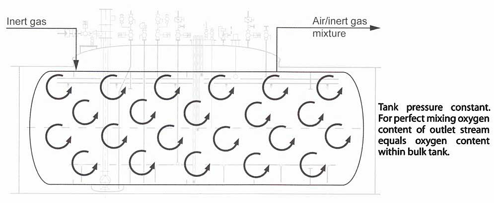
It is important to monitor the oxygen content at several positions in a cargo tank during inerting operations. Dead pockets and layering must be avoided.
Gassing up
Gassing-up, as with inerting, is a procedure that changes the atmosphere within the cargo tanks and pipework system.
The gassing-up process involves replacing the inert gas with cargo vapour, or the replacement of one cargo vapour with another compatible cargo vapour in the case of ammonia it would involve replacing the air in the tank with ammonia vapour.
Purging or gassing-up is the changing of the tank atmosphere from inert gas (or air for NH3) to cargo vapour.
The complexity of the gassing-up operation depends on a number of factors, including cargo characteristics such as vapour density, whether the purging medium will be supplied as a liquid or a vapour and whether gassing-up is being carried out at sea or at the loading terminal.
If the cargo to be loaded is LPG and the previous cargo was NH3, likely charter requirements will be that the tank atmosphere must have no more than 2 ppm NH3.
The basic principles of “displacement” or “dilution” that are applied to primary inerting also apply to gassing-up. However, when gassing-up, there is usually a greater vapour density difference between the cargo being loaded and the inert gas being displaced. This vapour density difference can be used to advantage.
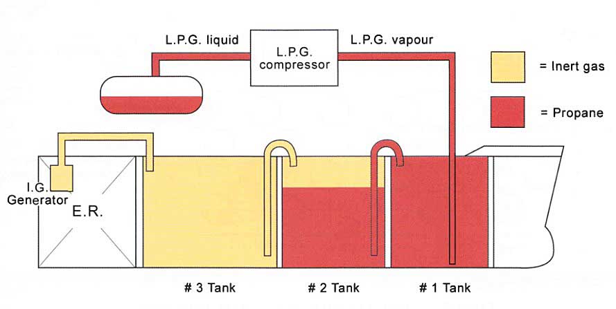
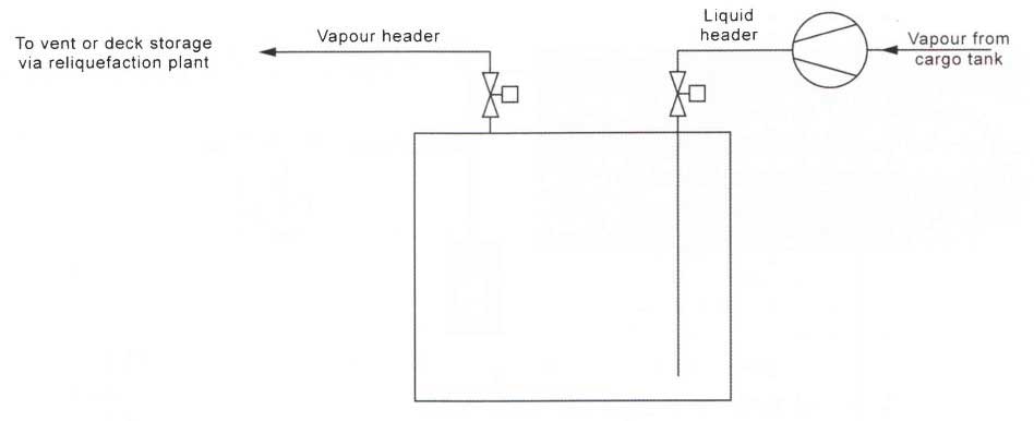
Gassing-up at Sea Using Liquid from Deck Storage Tanks
Larger LPG carriers (of the 30 000 m3 range) are frequently fitted with deck storage tanks that will allow storage of an appropriate amount of grades such as propane, butane or ammonia. This will give the ship the ability to conduct a grade change while on passage and arrive gassed-up and cooled down and ready to load the next cargo.
Deck storage tanks arc independent cylindrical tanks of Type “C” construction that have no insulation.
Gassing up while on passage is conducted on larger fully refrigerated ships which are equipped with deck storage tanks.
To allow grade changes at sea on fully refrigerated LPG carriers, the capacity of the deck tanks will be between 250-350 m3 with a typical safety relief valve setting of 26 barg.
Deck tanks also provide additional cargo storage so that, on completion of discharge and before changing grades, wastage and unnecessary venting of the cargo into the atmosphere can be reduced.
Some loading terminals do not permit purging and cooling down alongside, particularly when the terminal has no vapour return facilities or when the terminal is in an environmentally sensitive area.
If cargo cannot be loaded into a main cargo tank, allowing the vessel to cool-down without the need to vent, it can be loaded into a deck tank to allow the vessel to go to sea or to anchor and prepare the cargo tanks for loading.
1 Gassing-up Cargo Tanks From the Deck Storage Tanks
On an 85 000 m3 LPG Carrier with 4 cargo tanks purging with ammonia, the cargo tank from the deck tank would be purged as follows:
- Connect the vapour outlet of the deck storage tank to the top of No. 1 cargo tank. In this example the pressure in the deck tank is 11 bar and the temperature of the vapour at the top of the deck tank is 23 °C.
- After approximately fourteen hours, cargo tank No. 1 should be full of ammonia vapour and cargo tanks 2 and 3 should be at levels of 50 % and 25 %.
- The pressure and temperature in the deck tank will, by this time, have fallen to approximately 0,5 bar and -30 °C.
- Using the water spray system on the deck tank, raise the pressure in the deck tank and continue purging through the top of No. 1 cargo tank.
- In a further six hours, cargo tank No. 2 should be full of ammonia vapour. In a further seven hours, cargo tank No. 3 will also be full, followed by No. 4 eight hours later.
2 Gassing-up Tanks Using the Deck Storage Tanks and the Cargo Vapouriser
As an alternative to using the deck spray to warm the liquid in the deck storage tanks, the cargo can be vapourised in the cargo vapouriser and introduced gradually into the top or bottom of the cargo tank (depending on its specific gravity), cascading the inert gas into other tanks or to the vent riser.
3 Starting the Reliquefaction Plant after Gassing-up
As the pressure in the tank is reduced by the reliquefaction plant, additional liquid may be routed to the tank spray rails to maintain that position.
Gassing-up Alongside
For most gas carriers, the gassing-up operation will be carried out with cargo loaded from shore as a liquid or vapour.
Venting of hydrocarbon vapours alongside a terminal is hazardous and most terminals and port authorities prohibit it if at the berth.
Another factor to be considered is the length of time that the ship will spend gassing-up cargo tanks alongside. At some terminals facilities exist to allow tank preparation prior to loading being carried out.
Most terminals prohibit venting of hydrocarbons at the berth.
Ships often prepare a single cargo tank to allow sufficient liquid to be taken on board for the ship to leave the berth, purge and cool-down the remaining cargo tanks and then return ready for loading.
A ship arriving alongside with inerted tanks must consider the following:
- Is venting allowed;
- Is there a vapour return facility available;
- If only one tank will be purged and cooled down and how much liquid will be required to be loaded to purge and cool-down the remaining tanks;
- Is it liquid or vapour that is available for purging?
If venting is not permitted alongside, a vapour return facility must be provided by the terminal. Either the ship’s cargo compressors or a jetty vapour blower will be used to handle the vapours.
Where gassing-up takes place alongside, loading should be at a carefully controlled rate and boil-off in the tanks should be allowed.
When the displacement method is used, the terminal may initially allow the displaced inert gas to be vented-up the mast. For cargoes such as VCM, all nitrogen and VCM vapour will be returned ashore for flaring.
Where the terminal provides a vapour supply for gassing-up, it can be introduced directly into the tanks at the top or bottom, depending on the vapour density.
If a ship arrives alongside with cargo vapour in its tanks, for gassing-up with the cargo to be loaded, the terminal will normally provide a vapour return line. The vapours taken ashore will usually be flared until the desired product specification is achieved. After this, cool-down can begin.
Cool-down
Cool-down is often carried out when berthed alongside, at the same time as the gassing-up operation. Cool-down is an important part of cargo tank preparation before loading.
Cool-down is when liquid is introduced into the cargo tanks to reduce the cargo tank temperature so that thermal stresses are minimised and pressure increase is controlled. The lower the cargo carriage temperature is, the more important the cool-down procedure becomes.
Cool-down is the introduction of liquid into the cargo tanks to reduce the cargo tank temperature.
The rates at which the cargo tanks can be cooled without creating undue thermal stresses will depend on the design and materials of the Liquefied Natural Gas and Liquefied Petroleum Gas Cargo Containment Systemcontainment system. For example:
- Type “C” cargo tanks, cool-down rates may be as high as 8 °C to 10 °C per hour.
- Type “A” cargo tanks may only be as high as 3 °C to 4 °C per hour (or less).
Cargo loaded from the shore or taken from the deck storage tanks should be lined-up, via the cargo tank spray lines, to maximise the rate of evaporation and enhance the cool-down process (sprayed liquid droplets are taking heat from the tank atmosphere).
The vapours produced by evaporation can be taken ashore or handled in the ship’s reliquefaction plant. If the vapours are handled in the reliquefaction plant difficulties may be experienced with incondensibles, such as inert gas. A close watch should be kept on compressor discharge temperatures and any inert/incondensible vapours vented from the top of the cargo condenser.
As the cargo containment system is cooled down, the thermal contraction of the tank causes a change in tank volume, which may then result in a pressure change in the external void spaces. Pressure control systems supplying air or inert gas will maintain these pressures, but they should be monitored as the cool-down progresses.
Cool-down should continue until liquid begins to form in the bottom of the cargo tank, which will be seen from the temperature sensors. In the case of cool-down of cargo tanks for fully-refrigerated ammonia, the pool of liquid formed will be about -30 °C while the top of the tank may still be -14 °C, i. e. a temperature gradient of 16 °C exists in the tank. This is a normal situation that will be experienced during cool-down, although the actual temperature gradient will depend on the size of the cargo tanks, position of the sprays, etc.
Once the cargo down, the cargo tanks have been cooled pipework and equipment can be cooled-down by circulating liquid through the system.
In a semi-refrigerated ship, if the cargo tank steel is limited to, as an example, a minimum temperature of -5 °C, subjecting the steel to lower temperatures should be avoided. It is necessary to maintain a pressure within the cargo tank that is at least equal to the saturated vapour pressure to stay within the limits of the minimum allowable steel temperature. This can be done by vapourising liquid using the cargo vapouriser and introducing vapour into the tank by the cargo compressor. Alternatively, the vapour can be provided from the shore.
Loading
Check the following before arrival:
- Condition and setting of the cargo tank relief valves;
- Remotely operated valves;
- Reliquefaction plant, maximum number of plants running to reduce tank pressures before loading;
- Gas detection systems;
- Alarms and other cargo controls;
- Any cargo manifold reducers that are fitted prior to arrival.
Before the loading operation begins, complete the ship/shore safety check-list (see 9.8).
The terminal should provide all necessary cargo information, including inhibitor certificates if inhibited cargoes such as VCM or butadiene are to be loaded.
While the Chief Officer completes the cargo survey, the Cargo Engineer and the OOW will set the cargo lines to the open position, leaving the manifold valves. The manifold will remain closed until immediately prior to loading.
Inhibitors are a cargo additive that prevents the polymerisation of the cargo for a specified time. They protect the liquid, but leave the vapour unprotected.
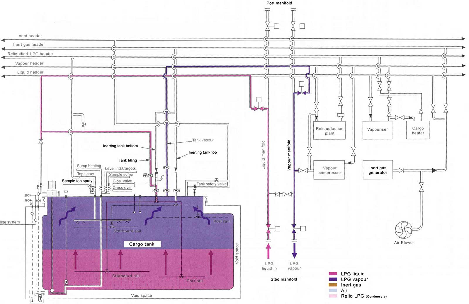
During loading, the vapour that is displaced in the cargo tanks by the incoming cargo must either be reliquefied by the ship’s own reliquefaction plant or returned ashore using a Vapour Return Line (VRL).
When loading with a VRL, cargo is loaded to the appropriate cargo tank and any vapours generated are removed from the tank and returned ashore via the VRL.
When loading with a VRL, the loading rate is based on the capacity of vapour the terminal can handle. However, when no VRL is provided the loading rate will be determined by the capacity of the ship’s reliquefaction plant (i. e. at the loading rate that it can control the pressure in the tanks).
On commencing loading note frosting of pipelines.
The early stages of loading are critical, particularly where the distance between the storage tank and jetty is large. This situation is worse if the jetty does not have a recirculation line so it is necessary to ensure the cargo is fully chilled before sending it to the ship, and to “ramp-up” loading rates as soon as possible to keep it chilled – especially in high ambient, hot sun conditions.
Loading rates are (normally) greater when loading with a VRL than when using the ships reliquefaction plant.
After the ship’s tanks have all received liquid, if cargo level floats are fitted, they should be periodically lifted off the tank bottom to ensure that they do not “freeze” to it. Tank pressures must be regularly observed and relief valves should not be allowed to lift. Loading rates should be reduced and, if necessary, stopped where difficulties are experienced in maintaining acceptable tank pressures. Tank pressure rise in the early stages of loading can be controlled to some extent by diverting some liquid to the cargo tank via the top sprays.
Fully-refrigerated LPG storage tanks ashore operate at a pressure of approximately 60 mbarg.
When loading, pressure in the cargo tanks should be kept as low as possible, keeping them at least 10 mb above atmospheric pressure when running the reliquefaction plant.
During loading, cargo tank pressures, temperatures and levels, interbarrier space pressures and manifold temperatures and pressures should all be monitored.
Once loading has settled, the de-ballasting operation will begin. As ballast handling arrangements for gas carriers are independent of the cargo system, de-ballasting takes place simultaneously with the cargo loading, subject to Regulations and Rules for Vessels to Carry Liquefied Gaslocal rules. It is easier to have the ship in an even keel state when topping off the tanks as this avoids the need to apply any corrections for trim. For the same reasons, list should always be avoided.
Notify the Chief Officer or Master if you note any differences between the observed stability data and the plan.
Ship stability and stress are of primary importance during loading and de-ballasting and their values must be checked against the stability book or the approved loading computer and cross checked against the plan.
Depending on the efficiency of the purging operation (during the grade change), significant quantities of gases that are incondensible may be present and, if no VRL is fitted, these incondensibles will have to be vented via the vent condenser or from the top of the cargo condenser (an example is nitrogen with a boiling point of -189 °C).
When venting incondensibles care must be taken to minimise the venting of cargo vapours to the atmosphere. As the incondensibles are vented, the condenser pressure will drop and the vent valve should be throttled and eventually closed.
Tank Filling Level
It is important to ensure that cargo tanks are filled to the appropriate level, in accordance with the IGC Code.
The volume of cargo that can be filled into any tank is governed by the following:
where:
- VL – is the maximum volume to which the tank may be loaded.
- V – is the volume of the tank.
- Pr – is the density of the cargo at a reference temperature.
- Pl – is the density of the cargo at the loading temperature and pressure.
While LPG Carriers load to 98 % capacity LNG Carriers of the Type “B” sphere design may have a dispensation from their Flag State and Class Society to load to as much as 99,5 %.
To reference temperature to be used in the calculation is either:
- In the circumstance where no cargo vapour pressure/temperature control is provided, on a fully-pressurised ship without reliquefaction plant, the temperature used corresponds to the vapour pressure of the cargo at the set pressure of the relief valves.
- In the circumstance when a cargo pressure temperature control is provided, i. e. ships with reliquefaction plant (semi- refrigerated or fully-refrigerated), the temperature of the cargo upon termination of loading, during transport or at unloading, whichever is the greater.
However, the IGC Code qualifies this calculation. lf the reference temperature would result in the cargo tank becoming liquid full before the cargo reaches a temperature corresponding to the vapour pressure of the cargo (at the set pressure of the relief valves), an additional pressure relief system must also be fitted to the cargo tank.

In the case of a fully-refrigerated ship where the relief valves are nominally set above atmospheric pressure, tanks can be loaded to 98 %. In the event of a fire, the tank relief valves would lift as the temperature and vapour pressure increases, not allowing the tank to become liquid full by thermal expansion.
However, where a semi-pressurised/fully-refrigerated ship loads the same fully- refrigerated cargo, the qualification of the IGC Code becomes critical. With such a ship, the tank relief valves may be set around 5 kg/cm2 and this means that, if a fully-refrigerated propane cargo al -42 °C was loaded to 98 % level, in the event of a fire the relief valves would not lift until the cargo temperature had reached a value corresponding to the saturated vapour pressure at the relief valve setting, in this case about 2 °C.
However, as liquid density decreases with temperature increase, the tank would be liquid full without any vapour space al about -34 °C and so would be hazardous. A gas carrier of this design must fit an additional pressure relief system, incorporating a relief valve that is set to lift at the saturated vapour pressure of the cargo at the reference temperature (i. e. maximum temperature during loading, loaded passage or discharge). This must be prevented from lifting during normal operations by an override arrangement (including fusible elements).
In a fire, the additional relief valve fusible link would melt, allowing the valve to lift and preventing the tank from becoming liquid full. Another alternative is to adjust the relief valve setting, as explained in Cargo Handling Systems and Specialised Equipment on LNG LPG Carriers“Pressure Relief Valves”.
Topping-off Tanks
During the load, the tanks should be staggered so that they finish in the desired order. As each tank finishes loading, the remote/manual loading valves should be closed-off.
To accurately top-off the tanks, loading rates should be reduced to an appropriate rate, which has been previously agreed with shore staff, toward the end of the loading operation.
It is good practice to re-check previously topped-off tanks to ensure that valves are not leaking and inadvertently “filling up”.
Always leave enough room in the last tank to load to allow for any draining.
On completion of the loading operation, the ship’s pipework should be drained back to the cargo tanks. The shore will clear the remaining liquid by blowing it with heated cargo vapour or nitrogen.
Once liquid has been cleared and the lines depressurised, manifold valves should be closed and the hose or loading arm disconnected from the manifold flange.
Operation of the Reliquefaction Plant
Cargo Handling Systems and Specialised Equipment on LNG LPG Carriers“LPG Reliquefaction Plant” provides a more detailed explanation of this summary.
During loading and on loaded passage it will be necessary to run the reliquefaction plant (where fitted).
When loading without a VRL, the maximum reliquefaction capacity will determine the rate at which the ship can load.
On loaded passage, cargo temperatures will be maintained or further refrigerated (as required) through the operation of the reliquefaction plant.
Before running the reliquefaction plant it is necessary to ensure that oil levels are correct in the compressors and that the glycol/water heating/cooling system is ready for operation, i. e. the header is topped-up and circulating.
If changing cargo grades, it may be necessary to change the compressor lubricating oil, especially from NH3 to LPG.
The cargo condenser cooling system must be operating, with either sea water circulating or with the refrigerant gas system running. Compressors should always be started and stopped in accordance with the manufacturer’s instructions. Compressor discharge valves should be opened and suction valves opened slowly to minimise damage from any liquid carryover. The cooling water outlet temperature should be adjusted in accordance with the manufacturer’s instructions.
The pressure in fully loaded cargo tanks will drop considerably when the cargo compressors are started.
The following should be checked frequently when the plant is running:
- Suction, interstage and discharge pressures;
- Lube oil pressures;
- Gas temperatures on the suction and delivery side of compressor. High discharge temperature switches protect the compressor;
- Current drawn by electric motor;
- Oil leakage from the shaft seal;
- Cooling water temperature.
The cargo compressor should be stopped in accordance with the manufacturer’s instructions. The compressor should be stopped, suction and discharge valves closed, and the glycol/water system left running to provide crankcase heating (or alternatively the lube oil heater should be switched on).
Sampling
Sampling of liquefied gases on board ships is usually conducted by drawing a sample of cargo from the fitted sampling points into a sample cylinder.
The sample cylinders are usually double ended stainless steel cylinders of 500 ml capacity, rated to 1 800 psig.
1 Sampling Technique
Personal Protective Equipment (PPE) that reflects the toxicity of the cargo must be worn.
To obtain a representative sample the product should be available at a pressure of 50 psig. (about 3,5 barg).
It is normal practice to start the cargo pumps and circulate the product back to the tank via the filling line. A valve on the circuit can be partially closed to create the required pressure. The cylinder is held vertically and purged by opening the sampling point valve with the cylinder valve (nearest to the cargo line) fully open. The purging rate can be controlled al all times by operating the cylinder valve at the opposite side of the cylinder. The cylinder should be filled and emptied at least twice to clean and cool the cylinder. Fill the cylinder as rapidly as pressure permits and maintain a through purge for 60 seconds.
The valve at the opposite side of the cylinder is closed, followed by the rapid closure of the sample point valve and the connected valve of the cylinder. (The connections on the sampling hose should permit gradual release of pressure).
With the cylinder held vertically, the bottom valve should be opened and approximately 20 % of the cylinder content released. This last element is important as it will allow expansion of the product during warming to ambient temperature without any substantial increase in pressure.
Loaded Passage
This section on loaded passage is primarily concerned with use of the reliquefaction plant to maintain or reduce the cargo temperature.
The general operation of the reliquefaction plant was described in Cargo Handling Systems and Specialised Equipment on LNG LPG Carriers“LPG Reliquefaction Plant”. However, it is important to protect the compressor from liquid carryover in the vapour suction line during heavy weather conditions. Although most reliquefaction plants have a suction knock-out drum, there is always a danger that large slugs of liquid are carried over into the compressor in heavy weather, so it may be prudent not to run the compressors in such conditions.
Incondensibles will have to be vented-off to minimise compressor discharge pressures and temperatures. To prevent polymerisation when butadiene cargoes are carried, the compressor discharge temperature must never exceed 60’C and the appropriate high discharge temperature switch must be selected. To prevent polymerisation when carrying VCM, compressor discharge temperatures should be limited to 90 °C.
When the condensate return from the reliquefaction plant is routed to the top sprays, in calm weather conditions the small vapour space in the tank combined with the absence of any liquid suction in the tank can cause a cold layer of liquid to form at the surface. This causes the compressors to reduce the vapour pressure after only a few hours running, when the bulk of the liquid has not yet been cooled. To avoid this, full reliquefaction plant capacity should be run on each tank independently and in sequence.
If the reliquefaction plant is drawing from all tanks but returning to one tank, this should be closely monitored to prevent overfilling.
The condensate return from the cargo condenser should be returned through a bottom connection to ensure circulation of the tank contents, so preventing any risk of in-tank rollover of different liquid densities. After the cargo has cooled the reliquefaction plant capacity can be reduced to a level that balances the heat flow through the tank insulation.
Discharge
When the ship arrives at the discharge port, tank pressures and temperatures should be as per the terminal’s requirements to achieve the maximum discharge rates.
The method of discharging the ship will depend on the type of ship, the cargo specification and the terminal storage. Three methods are employed by the various types of gas carriers:
- Discharge by deep well or submersible pumps.
- Discharge by deep well or submersible pumps in series, with a booster pump and through a cargo heater.
- Discharge by vapour pressure alone.
Discharge by Deep Well or Submersible Pumps
Discharging by centrifugal cargo pumps, either alone or in series with booster pumps, is the method used by most ships. An understanding of the use of centrifugal pumps assists efficient cargo discharge.
During discharge, cargo boil-off caused by heat permeating through the tank insulation occurs continuously and generates vapour within the tank. Depending on discharge rates, cargo temperature, ambient temperature, etc, this may on its own be sufficient to maintain cargo tank pressure at acceptable levels.

If the vapours generated within the tanks are insufficient to counter the discharge rate it will be necessary to add vapour to the tank if discharge is to continue at this rate. Vapour can be received from the shore using a VRL, or may be generated on board if the ship is fitted with a cargo vapouriser. Liquid is normally taken from the discharge line and diverted through the vapouriser.
When tank levels approach 1 metre, the pump current (amps) and pump discharge pressure should be closely observed. If fluctuations are noted, throttle the discharge valve slowly until stability is achieved as this avoids cavitation. A low pressure differential between the pump discharge pressure and the tank pressure will trip the pumps.
A low amps reading indicates that the pump is cavitating. This will stop the pump.
As each tank nears completion of discharge, the cargo pump discharge valve should be throttled to maintain suction while stripping the cargo liquid level. Manufacturer’s instructions should be consulted to verify the level at which throttling should begin and the pump pressure must be maintained to achieve maximum stripping performance. Each pump should be closely monitored to achieve the best results without the pump running dry.
Centrifugal pumps should be started against a valve that is closed or “cracked open” to reduce the starting load.
When starting centrifugal pumps it is good practice to close the valve before starting the pump and cracking it open a 1/4 turn to prevent it jamming on the valve seat.

The discharge valve should then be opened and the liquid discharged ashore. As the discharge of cargo proceeds, the liquid level in the cargo tanks should be monitored and the ship ballasted as per the discharge plan. The ship should have sufficient stern trim at the end of the discharge to assist tank stripping (depending on the position of the cargo pumps as some VLGC’s have the pumps in their 4th cargo tank positioned in the centre).
If the cargo vapouriser is operated it will be necessary to monitor instrumentation and control systems, i. e. liquid level, temperature, pressure, etc.
Depending on the type of gas carrier the duration of the ballast voyage and the loading terminal requirements, it will be necessary to retain some cargo liquid on- board for keeping the cargo tanks cool. This is known as “heel”. The quantity Remaining On Board (ROB) will depend on the length of the ballast passage, but it should be kept to a minimum.
On completion of the cargo discharge all liquid lines, cargo hoses and hardarms must be cleared. This can be done from the ship to the shore using a cargo compressor blowing the lines clear with “heated cargo vapour”, or from the shore to the ship by blowing nitrogen, injected at the base of the chiksan arm to clear all the lines back to the tanks. Once the lines are cleared of liquid and depressurised the ship/shore connection can be broken.
Cargo calculations for discharge must allow for liquid and vapour quantities before and after discharge. The calculations are carried out in exactly the same manner as the loading calculations.
Discharge Using Booster Pumps and Cargo Heater
Where cargo is transferred from a refrigerated ship into pressurised storage, is necessary to warm the cargo during discharge. This requires the cargo booster pump and cargo heater to be run in series with the main cargo pump, generally resulting in a considerable reduction in the discharge rate.
To operate the booster pump and heater, is necessary to establish a sea water flow through the heater. The pump and heater may then be slowly cooled down prior to operation by carefully bleeding in liquid from the main cargo pump discharge. Once cooled down, the discharge valve can be opened until the desired outlet temperature is reached. It is necessary to maintain suction to the booster pump at all times.
When using the cargo heater, the sea water outlet temperature must not fall below +2 °C.
Cargo heating always presents a risk of freezing-up the heater. In addition to checking the cargo outlet temperature and the booster pump suction pressure during discharge, attention should be paid to the seawater inlet and outlet temperatures and pressures.
Throttling of the tank mounted pump discharge valve must only be done if the pump is not operating in series with a booster pump.
If the deep well pump valve was throttled in such an instance, the booster pump would cavitate, causing considerable damage.
Discharge by Vapour Pressure
This is only possible where Type “C” tanks are fitted. It is an inefficient and slow method of discharge and is restricted to small vessels of the fully pressurised type. The vapour pressure above the liquid is increased and the liquid transferred ashore.

Ballast Passage
On liquefied gas carriers there will always be some product Remaining On Board after discharge, known as “heel”.
The heel is used to keep the cargo tanks at a reduced temperature during the ballast voyage if the same grade of cargo is to be loaded at the next port.
LNG or LPG ROB after discharge is known as “heel”.
For LPG cargoes, the cargo remaining after discharge will be sufficient to provide cooling for the tanks throughout the duration of the ballast passage. Compressors should be run and condensate returned through the spray rails to allow for arrival at the next load port with tanks and the quantity of remaining product at the lowest possible temperature.
If the ship is to load a new cargo, the cargo remaining on board must be vapourised and vented or transferred to a deck storage tank while at sea to avoid contamination and allow the maximum quantity of the new cargo to be loaded. The grade change may require the tanks to be gas freed and taken back to fresh air for tank inspection.
You must ensure operations are planned thoroughly using the equipment as designed on board. No short-cuts from procedure should be taken.
Changing Grades/Gas Freeing
If it is necessary to gas free the vessel to change grade, which will be the case prior to loading chemical gases such as VCM, ethylene or butadiene, the success of the operation will depend on the efficiency of removal of residual liquid from the cargo tanks and pipework system. This will be influenced by the type of containment system and the Cargo Handling Systems and Specialised Equipment on LNG LPG Carrierscargo handling facilities provided.
During a grade change, each m3 of LPG cargo left in the system can form up to 250 m3 of vapour, hampering the purging of cargo vapour from the tanks.
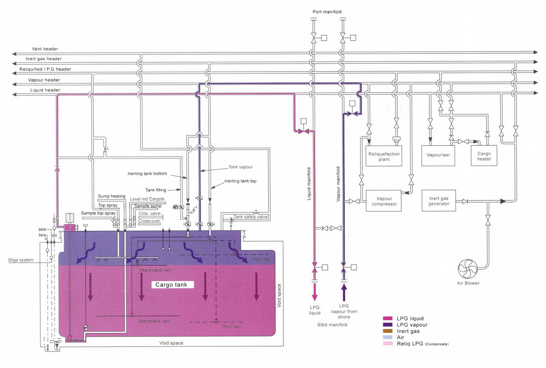
Liquid Freeing
For a ship with Type “C” cargo tanks, a stripping line is provided for each tank. By creating pressure in the cargo tanks using the cargo compressor, residual liquid can be pressurised from the bottom of the cargo tank sump via the stripping line and either released overboard if the ship is at sea, or collected into one tank for returning ashore. Draining and stripping should continue until all liquid is removed from the cargo tanks. This should be verified through the bottom sampling line.
The tank pressure necessary to remove all liquid depends on the cargo SG and the height of the cargo tank and dome.
For ships with tanks other than Type “C”, liquid freeing by pressure is not possible and vapourisation must be carried out. Hot gas is provided either by the use of puddle heating coils or by the supply of hot gas directly to the bottom of the cargo tanks.
Hot gas is gas from the compressor discharge, i. e. before the condenser stage.
On ships with “puddle heating” coils, the liquid puddle of LPG evaporates and the vapour in the coil condenses. Condensate can then be put ashore, overboard or returned to the deck storage tank.
For all types of LPG tank, “hot gas” comes from the compressor discharge. Vapour is taken from the tanks and passed through the compressors where the heat of compression results in an increase of temperature in the vapour discharged. This heat of compression is transferred to any remaining liquid, causing its evaporation.
Puddle heating coils are used during grade change to evaporate off any remaining LPG in the cargo tank.
Where hot gas is introduced directly into the bottom of the tank, via the liquid loading line, the liquid puddles are flashed/boiled-off. The vapours are vented-up the riser when the ship is at sea or they are condensed in the reliquefaction plant and sent either ashore, overboard or to the deck storage tank.
When all tanks have been satisfactorily liquid freed, all pipes, vessels, heat exchangers, etc, must be blown free of liquid and drained through any drain valves.
Note that the sump temperature will not vary until it is liquid free, at which point its temperature will quickly increase to the tank’s ambient temperature.
Purging
When cargo tanks are being gas freed for tank inspection or dry-dock, it may be necessary to warm-up the cargo tank by circulating hot gas throughout the system before inerting takes place.
Warming-up is important where cargo tanks are at low temperatures, e. g. propane at -42 °C.
Once the cargo system has been satisfactorily liquid freed, purging can commence.
Purging is the replacement of the present tank atmosphere with another cargo vapour (e. g. change over from butane – propane) or inert gas.
Purging a tank, is to “purge” the tank of the existing atmosphere with a new LPG vapour or IG.
The level of “purging” is determined by the type of cargo and the permissible cargo contamination level.
When tanks are to be opened for inspection, purging with inert gas is always necessary to reduce the hydrocarbon level within the tank to safe quantities before introducing fresh air to the tank.

Certain cargoes present difficulties in terms of purging operations. If a ship has been carrying ammonia it can be time consuming to remove all the ammonia vapours to achieve permissible concentrations before loading an LPG cargo, where limits of 2 ppm are imposed. Purging of ammonia is usually done using fresh air. This is swept through the cargo system until ammonia concentrations are less than 100 ppm at which point it can then be supplemented by fans and concertina hoses passed through the tank lids until the concentration is less than 2 ppm.
When grade changing from NH3 to Propane, the NH3 limit in the tank is 2 ppm.
On older ships internal tank surfaces may become saturated with ammonia, resulting in difficulty in removing this from the porosity of the tank surface. Using a fine water spray with all the tank openings open may remove the residue, but attention must be paid to the cautions, which you can read below.
Water Washing after Ammonia Cargoes
Ammonia is soluble washing can be an in fresh water and so effective method of removal. Note: NH3 and H2O = Ammonia hydroxide, which is a caustic solution.
However, the high solubility can lead to the creation of vacuum conditions within a tank and so it is important to ensure adequate air entry during the process and to dilute the caustic residue with more water.
After water washing it will be necessary to pump the water overboard, using either the cargo pumps or portable pumps. Care must be taken not to overload the pump motor when pumping water, as it has an SG of 1.

The tank and pipework systems must be thoroughly dried before proceeding with preparations for cargo loading not only to avoid ice or hydrate formation but also to remove water that might otherwise retain ammonia contamination. It is recommended that systems are completely clean, rust free and have minimal internal tank structures.
To achieve a dry tank after purging it is important that:
- The tanks are ventilated with air that has a dew point of less than the tank temperature. This avoids condensation on the tank surfaces.
- The tanks and cargo system are ventilated at the highest temperature feasible to encourage the release of ammonia from any rusted surfaces as ammonia is released 10 times faster at 45 °C than at 0°C.
Aeration of Cargo Tanks
Once the tanks have been warmed and the hydrocarbon concentration has been reduced using inert gas, the tanks can be opened to fresh air Ventilation using blowers or fans can now continue until the oxygen content, as monitored at various levels and positions in the tank, is 20,9 %.
Important Points when Changing LPG Cargoes
From Ammonia to LPG
Gas free the cargo tanks, aerate with dry air inert the tank and gas-up with LPG vapour and cool-down in preparation to load.
The Ammonia content must be reduced to below 2 ppm when gas freeing. It is probable that the concentration of ammonia in the cargo tanks may be reduced further during the gassing-up process. It is most likely that compressor lube oil sumps will require change with clean new lube oil.
From LPG to Ammonia
Gas free the cargo tanks, aerate with dry air gas-up with ammonia vapour and cool-down.
The carbon dioxide content from the inert gas generator and other impurities present in the gas will form carbamates, so inert gas is not used for that reason. In certain high purity ammonia trades it may be necessary to “sweep” the tanks with nitrogen.
To change between: Butane, Butene, Butadiene, Propane, Propene
It is sufficient to puddle heat the liquid remaining from the previous cargo out of the tanks, and then cool-down. As butene (butylene), propene (propylene) and butadiene are unsaturated hydrocarbon gases, they must be loaded into an oxygen free tank.
An oxygen free tank is more important than the slight contamination that may arise from the vapour of the product previously carried. This can be minimised by flushing through with the vapour of the cargo to be loaded so, unless specifically instructed to do so, the ship should not gas free prior to loading. If the tanks are gas freed prior to loading butene or propene, the tanks must be inerted and the oxygen level reduced to 2 % or less, and reduced to 0,1 % prior to loading butadiene. Cargo tanks must be gas freed after the carriage of ammonia.
Previous Butadiene Cargo
Some terminals will not accept a vessel if the previous cargo was butadiene unless the ships tanks and associated pipework have been purged with nitrogen to ensure a butadiene level of 1 ppm or less.
From Butane to Propane or vice versa
It is not always necessary to gas free. Many ports will accept the “old” vapour ashore in the return vapour line when the ‘new’ cargo is being loaded or when the tank is being precooled. However, more demanding standards are likely when changing from propane – butane as the latter ls more commonly used in portable domestic cylinders. Further guidance on this will come from the Charterer if it is appropriate.
Tank Cleaning Table Liquefied Gas
- Boil-off liquid residue and reduce tank pressure to atmospheric.
- Boil-off liquid residue in absence of specific instructions.
- Purge tank with vapour of cargo to be loaded – via top purge grid.
- Purge tank with vapour of cargo to be loaded – via bottom purge grid.
- Inert with dry inert gas – via top purge greed.
- Inert with dry inert gas – via bottom purge grid.
- Ventilate with dry air – via top purge grid.
- Ventilate with dry air – via bottom purge grid.
- Purge with dry nitrogen – via top purge grid.
| Next cargo | |||||
|---|---|---|---|---|---|
| Last cargo | Propane | Butanes | Ammonia | VCM | |
| Propane | 2 | 1, 5, 7, 3 | 1, 5, 9, 4 | ||
| Butanes | 2 | 1, 5, 7, 3 | 1, 5, 9, 4 | ||
| Ammonia | 1, 8, 6, 4 | 1, 8, 6, 4 | 1, 8, 6, 9, 4 | ||
| VCM | 1, 5, 4 | 1, 5, 4 | 1, 5, 7, 3 | ||