Gas tank rules are critical for ensuring the safe transport and storage of gases in maritime operations. These regulations cover various tank types, including Type A, B, and C tanks, as well as membrane and semi-membrane designs. Compliance with these rules helps to mitigate risks associated with leaks and accidents, protecting both the environment and human life.
Additionally, the materials used in tank construction and insulation play a vital role in maintaining safety standards. Understanding and adhering to gas tank rules is essential for all stakeholders in the shipping industry.
General
The overall layout of a gas carrier is similar to that of the conventional oil tanker from which it evolved. The cargo containment system and its incorporation into the hull is, however, very different due to the need to carry cargo under pressurized, or refrigerated conditions; or under a combination or pressure and refrigeration.
Gas carrier designed for pressurized cargoes can usually be identified by cylindrical or spherical tanks which may project through the deck. Similarly the LNG carrier with spherical tanks protruding above main deck can also be easily recognized by its distinctive profile and much larger size. Gas carriers designed to carry their cargo at atmospheric pressure in prismatic tanks are not easily distinguished from oil tankers except their freeboard which is significantly greater. This greater buoyancy results from cargo of a much lower density than most oils and the requirement to have totally segregated tanks for ballast.
To examine the design of these ships IMO developed Gas Code which applies to all gas carriers. There are three Gas Codes and these are:
Gas Carriers built after June 1986 (the IGC Code). The Code which applies to new gas carriers (built after 30th June 1986) is the International Code for the Construction and Equipment of Ship Carrying Liquefied Gases in Bulk. In brief this code is known as IGC Code. The IGC Code, under amendments to Safety of Life at Sea Convention (SOLAS), is mandatory for all new ships. As proof a ship complies with the code, an International Certificate of Fitness for the carriage of Characteristics of Natural Liquefied GasesLiquefied Gases in Bulk should be on board.
In 1993, the IGC Code was amended and new rules came into effect from 1 st July 1994. Ships on which construction started on or after 1st October 1994 should apply the amended version of the code but ship built earlier may comply with previous edition of the IGC Code.
Gas Carriers built between 1976 and 1986 (the GC Code). The regulation covering gas carriers built after 1976 but before July 1986 is included in the Code for the Construction and Equipment of Ships Carrying Liquefied Gases in Bulk. It is known as the Gas Carrier Code or GC Code in short.
Gas Carriers built before 1977 (the Existing Ship Code). The regulation covering gas carriers built before 1977 are contained in the code for Existing Ships Carrying Liquefied Gases in Bulk. Its content is similar to the GC Code.
The Existing Ship Code was completed in 1976 after the GC Code has been written. It therefore summarize current shipbuilding practice at that time. It remains as an IMO recommendation for all gas carriers in this older fleet of ships. The code is not mandatory but is applied by some countries for ship registration and in other countries as a necessary fulfilment prior to port entry.
Some of the factors to be taken into consideration which affect the design of gas ships are:
- Types of cargo to be carried.
- Condition of carriage (fully pressurized, semi-pressurized, fully refrigerated).
- Type of trade and cargo handling flexibility required by the ship.
- Terminal facility available when loading or discharging the ship.
Perhaps more than any other single ship type, the gas tanker encompasses many different design philosophies. Nowhere is this more apparent than in considering the different types of cargo containment system which have been adopted.
A cargo containment system is the total arrangement for containing cargo including, where fitted:
- A primary barrier (the cargo tank);
- Secondary barrier (if fitted);
- Associated thermal insulation;
- Any intervening spaces, and;
- Adjacent structure, if necessary, for the support of these elements.
The basic tank type utilized on board gas carriers are in accordance with the following:
1 Independent Tanks.
2 Membrane Tanks.
3 Semi-membrane Tanks.
4 Integral Tanks.
5 Internal Insulation Tanks.
Independent Tanks
Independent tanks are completely self-supporting and neither form part of the ship’s hull nor contribute to hull strength. There are 3 different types of independent tanks for gas carriers: types A, B and C.
Type «A» tanks
Type «A» tanks are constructed primarily of flat surfaces. The maximum allowable tank pressure in the vapour space for this type of system is 0,7 barg; this means cargo must be carried in a fully refrigerated condition at or near atmospheric pressure (for NYK v/ls max pressure of MARVS is 28 kPa or 0,28 kg/cm2 ).
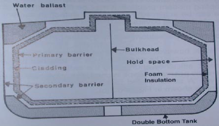
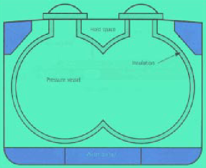
This is a self-supporting spherical tank which requires conventional internal stiffening. In the above tank is surrounded by a skin of foam insulation, where perlite insulation is used it would be found filling the whole of the hold space.
For a fully refrigerated LPG carrier (which not carry cargoes below -55 Deg C) the secondary barrier must be a complete barrier capable of containing the whole volume at a defined angle of heel and may form part of ship’s hull, as shown on above figure, means ship’s hull must be of special steel capable to withstand low temperature.
The space between the cargo tank (primary barrier) and the secondary barrier is known as hold space, is filled with inert gas to prevent a flammable atmosphere being created in the event of primary barrier leakage.
Type «B» tanks
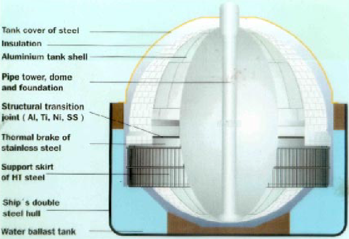
Type «B» tanks can be constructed of flat surfaces or they may be of the spherical type. This type of containment system is subject of more detailed stress analysis compared to tank «A» system. The most common are Kvaerner Moss, requires only a partial secondary barrier, in the form of a drip tray. A protective steel dome covers the primary barrier above the deck level and the insulation is applied to the outside of the tank. The Type «B» spherical tank is almost exclusively applied to the LNG trade.
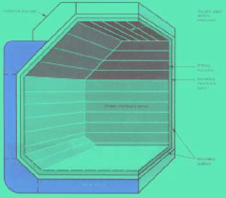
A Type «B» tank, however need not be spherical. There are Type «B» tanks of prismatic shape in LNG service. The prismatic Type «B» tank has the benefit of maximizing ship hull volumetric efficiency and having the entire cargo tank place beneath the main deck.
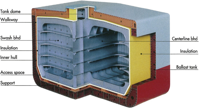
Where the prismatic shape is used the maximum design vapor space pressure is as for Type «A» tank, limited to 7 barg. A drawing of a self supporting prismatic Type «B» tank is shown in the figure 2.
Type «C» tanks
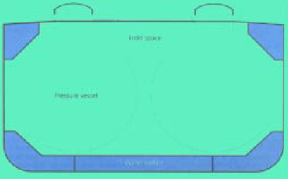
Type «C» tanks are normally spherical or cylindrical pressure vessels having design pressure higher than 2 barg.
Membrane Tanks
Membrane tanks are not self-supporting, like the independent tanks, but are supported through the insulation by the hull of the ship. The concept of the membrane containment is based on a very thin primary barrier (membrane -0,7 to 1,5 mm thick) which is supported through the insulation. These tanks must be provided with a secondary barrier to ensure the integrity of the total system in view of primary barrier leakage. Generally the design of a membrane tank.
There are two principal types both named after the companies who designed them namely:
1 Gaz Transport membrane system &.
2 Technigaz membrane system.
Semi-Membrane Tanks
The semi-membrane concept is a variation of the Key Characteristics of Membrane Tanks Systemsmembrane tank system. The primary barrier is much thicker than that in the membrane system, having flat sides and large residue corners. The tank is self-supporting when empty but not in the loaded condition.
In this condition the liquid (hydrostatic) and vapour pressures acting on the primary barrier are transmitted through the insulation to the inner hull as is the case with membrane system.
Integral Tanks. The integral tanks form a structural part of the ship’s hull, and are affected in the same manner and by the same load& which stress the hull structure These tanks are not normally allowed for cargoes of which the temperature is below -10 °C describes generally an integral tank.
Internal Insulation Tanks. Internal insulation tanks are not self-supporting and consisting instead of thermal insulation materials which contribute to the cargo containment, and are supported by the structure of the adjacent inner hull or of an independent tank. The inner surface of the insulation is exposed to the cargo.
Materials of Construction and Insulation
Construction Material. According to the gas code ships carrying fully refrigerated LPG cargoes may have tanks capable of withstanding temperatures down to -55 Deg C. This is normally determined by ship owner depending on the cargo expected to carry. This is often determined by the boiling point of the liquid propane at atmospheric pressure and, hence, cargo tank temperature limitations are frequently set at about -46 Deg C. To achieve this service temperature, steel such as fully killed, fine grain, carbon-manganese steel, sometimes alloyed with 0,5 percent nickel, are used.
Ships Survival Capability & Ship Types
The Master of the ship will be supplied with an approved loading and stability book. This will contain details of typical service conditions, loading, unloading and ballasting operations, provisions for evaluating other conditions of loading and a summary of the ship’s survival capabilities. The booklet will contain sufficient information to enable the Master to load and operate the ship in a safe and seaworthy manner.
Read also: Liquefied Gas Carrier Types
To safeguard the ship & the environment, the A Study on Support Arrangement of a Cargo Tank for Tank Type-A Liquefied Petroleum Shipscargo tanks should be protected from penetration in case of damage in case of contact with jetty or tug, collision or stranding. This is achieved by locating them at specified minimum distance inboard from ship’s shell plating.
Ships subject to the Code should be designed to one of the following standards:
- A type 1G ship is a gas carrier intended to transport products indicated in IGC Code chapter 19 (Summary of Minimum requirements) which require maximum preventive measures to preclude the escape of such cargo.
- A type 2G ship is a gas carrier intended to transport products indicated in IGC chapter 19 which require significant preventive measure to preclude the escape of such cargo.
- A type 2PG ship is a gas carrier of 150 m in length or less intended to transport products indicated in IGC chapter 19 which require significant preventive measures to preclude the escape of such cargo, and where the products are carried in independent type C tanks having MARVS of at least 7 bar gauge and a cargo containment system design temperature of –55 deg C or above. A ship of this description but over 150 m in length is considered a type 2G ship.
- A type 3G ship is a gas carrier intended to carry products indicated in IGC chapter 19 which require moderate preventive measures to preclude the escape of such cargo.
Thus a type 1G ship is intended for the transportation of products considered to present greatest overall hazard & type 2G/2PG/3G for products of progressively lesser hazard. If a ship is intended to carry more than one product listed in IGC chapter 19, the standard of damage should correspond to that product having the most stringent ship type requirement.
Location of Cargo Tanks
Cargo tanks should be located at the following distances inboard:
- Type 1G ships: from the side shell plating not less than the transverse extent of damage specified above and from the moulded line of the bottom shell plating at centerline not less than the vertical extent of damage specified above and nowhere less than 760 mm from the shell plating.
- Type 2G/2PG and 3G ships: from the moulded line of the bottom shell plating at centerline not less than the vertical extent of damage specified above and nowhere less than 760 mm from the shell plating.
The vertical extent of bottom damage should be measured to the inner bottom when membrane or semi membrane tanks are used, otherwise to the bottom of the cargo tanks. The transverse extent of side damage should be measured to the side of the cargo tanks.
Standard of Damage
- A type 1G ship should be assumed to sustain damage anywhere in its length.
- A type 2G ship of over 150 m in length should be assumed to sustain damage anywhere in its length.
- A type 2G ship of 150 m in length or less should be assumed to sustain damage anywhere in its length except involving either of the bulkheads bounding a machinery space.
- A type 2PG ship should be assumed to sustain damage anywhere in its length except involving transverse bulkhead spaced further apart than the longitudinal extent of damage as specified in damage assumption.
- A type 3G ship of 125 m in length or more should be assumed to sustain damage anywhere in its length except involving transverse bulkheads spaced further apart than the longitudinal extent of damage specified in damage assumptions.
- A type 3G ship less than 125 m in length should be assumed to sustain damage anywhere in its length except involving transverse bulkheads spaced further part than the longitudinal extent of damage specified in damage assumption and except damage involving the machinery space when located aft.
IMO Surveys
- An initial survey before the ship is put into service.
- A periodic survey not exceeding 5 years.
- A minimum of one intermediate survey.
- A mandatory annual survey within three months before or after the anniversary date of the certificate.
Certificate of Fitness
- An additional survey general or partial whenever any important repairs or renewals are made.
The above surveys are additional to normal ship surveys. Kindly refer to copy of Certificate of Fitness in the appendix.
Dual Compatibility – Chemical & Gases
These General International standards for the construction and equipment of ships carrying dangerous chemicals in bulk are defined in the IBC Code. When carriers have the capability of transporting chemical gas cargoes then the vessel must meet the requirements of both IGC Code and IBC Codes as designated in Chapter 19 of the IGC Code.

- Study on the completion of an EU framework on LNG-fuelled ships and its relevant fuel provision infrastructure, LOT 1 Position paper: Towards harmonized EU LNG bunkering guidelines, DNV-GL, 2016.
- Study on the completion of an EU framework on LNG-fuelled ships and its relevant fuel provision infrastructure, LOT 1 Final Report, DNV-GL, 2016.
- LNG Bunkering Guidelines IACS Recommendation n. 142, on LNG Bunkering, IACS, 2016.
- ISO/TS 18683:2015. (15-Jan. 2015). Guidelines for systems and installations for supply of LNG as fuel to ships. Technical Specification.
- Society for Gas as a Marine Fuel (SGMF). (2015). Gas as a marine fuel, safety guidelines, Bunkering. Version 1.0, February 2015.
- ISO 20519:2017. Ships and marine technology – Specification for bunkering of gas fuelled ships. (International Standard).
- IEC 60079-10-1. (2015). Explosive atmospheres – Part 10-1: Classification of areas – Explosive gas atmospheres.
- Directive 1999/92/EC – ATEX of the European Parliament and of the Council of 16 December 1999 on minimum requirements for improving the safety and health protection of workers potentially at risk from explosive atmospheres (15th individual Directive within the meaning of Article 16(1) of Directive 89/391/EEC).
- API RP-500. 1997. Recommended practice for classification of locations for electrical installations at petroleum facilities classified as CIass 1, Division 1 and Division 2. Washington. D.C: API.
- API RP-505. 1997, Recommended practice for classification of locations at petroleum facilities classified as Class I, Zone 0, Zone 1 and Zone 2. Washington, D.C. API.
- NFPA 497. 2012, Recommended practice for the classification of flammable liquids, gases or vapours and of hazardous (classified) locations for electrical installations in chemical process areas. Quincy, MA: NFPA.
- IEC EN 60079-10-1 Ed.1.0, 2008. Electrical apparatus for explosive gas atmospheres – Part 10-1: Classification of areas – Explosive gas atmospheres. International Electrotechnical Commission.
- Commission Decision 2010/769/EU of 13 December 2010 on the establishment of criteria for the use by liquefied natural gas carriers of technological methods as an alternative to using low sulphur marine fuels meeting the requirements of Article 4b of Council Directive 1999/32/EC relating to a reduction in the sulphur content of certain liquid fuels as amended by Directive 2005/33/EC of the European Parliament and of the Council on the sulphur content of marine fuels (OJ L 328, 14.12.2010, p. 15).
- USCG CG-OES Policy Letter 02-14 – Guidance Related To Vessels And Waterfront Facilities Conducting Liquefied Natural Gas (LNG) Marine Fuel Transfer (Bunkering) Operations.
- ADN – European Agreement concerning the International Carriage of Dangerous Goods by Inland waterways (Update version ADN January 2017).
- ADR – European agreement concerning the International Carriage of Dangerous Goods by Road (Update version ADR January 2017).
- Rhine Vessel Inspection Regulations (RVIR).
- EU general risk assessment methodology (Action 5 of Multi-Annual Action Plan for the surveillance of products in the EU (COM(2013)76) – Document 2015-IMP-MSG-15 – 16 October 2015.
- Safety Study, Chain analysis: Supplying Flemish ports with LNG as a marine fuel, Analysis of safety aspects, June 2012.
- EN 1160 – Installations And Equipment For Liquefied Natural Gas – General Characteristics Of Liquefied Natural Gas, NBN, 1st edition, August 1996.
- ESD Arrangements & Linked Ship/Shore Systems for Liquefied Gas Carriers, SIGTTO First Edition 2009 – SIGTTO.
- M. Kofod & S. Hartman, T. Mundt – Review of Recent Well-to-Wake Greenhouse Gas Studies evaluating the use of LNG as a marine Fuel, IMO MEPC/INF.15.
- LNG Access Code for Truck Loading for The Zeebrugge LNG Terminal – Based on version approved by the CREG on September 19th 2013 – Applicable as of January 1st 2014 – FLUXYS.
- Guidance for the Prevention of Rollover in LNG Ships – SIGTTO – First Edition 2012.
- Wang, Siyuan & Notteboom, Theo – The role of port authorities in the development of LNG bunkering facilities in North European ports, 14 January 2015, World Maritime University 2015.
- Verhoeven P (2010) A review of port authority functions: towards a renaissance? Marit Policy Manag 37:247-270.
- Society for Gas as a Marine Fuel (SGMF). (2017). Gas as a marine fuel, safety guidelines, Bunkering. Version 2.0, February 2015.
- COM(2003) 515 final – Communication from The Commission concerning the non-binding guide of good practice for implementing Directive 1999/92/EC of the European Parliament and of the Council on minimum requirements for improving the safety and health protection of workers potentially at risk from explosive atmospheres, Brussels, 25.8.2003.
- Davies, P. (2016) – Bunkering LNG: Setting the Safety Zone, 7th Motorship Gas Fuelled Ships Conference, November 2016.
- International Association of Oil & Gas Producers. (1-Mar 2010). Risk Assessment Data Directory – Process Release Frequencies. Report No. 434 – 1, 1 March 2010). Pertinent data from this report is summarised in: Davies & Fort, (Sept 2012), LNG as Marine Fuel – Likelihood of LNG Releases, Journal of Marine Engineering and Technology.
- PGS2 – TNO Yellow Book – Methods for the calculation of physical effects, due to releases of hazardous materials (liquids and gases) – CPR 14E (3rd Edition, 2005) – TNO – The Netherlands Organization of Applied Scientific Research.
- OECD Guiding Principles for Chemical Accident Prevention, Preparedness and Response, Guidance for Industry (including Management and Labour), Public Authorities, Communities, and other Stakeholders – 2nd Edition (2003) – OECD Environment, Health and Safety Publications.
- DNVGL-RP-G105 Edition October 2015 – Development and operation of liquefied natural gas bunkering facilities, Recommended Practice, DNV GL, 2015.
- USCG CG-OES Policy Letter No. 01-17 – Guidance for Evaluating Simultaneous Operations (SIMOPS) during Liquefied Natural Gas (LNG) Fuel Transfer Operations.
- LGC NCOE Field Notice 01-2017 – 14-Aug-17 – Recommended Process For Analysing Risk Of Simultaneous Operations (SIMOPS) During Liquefied Natural Gas (LNG) Bunkering.
- An Overview of Leading Software Tools for QRA, American Society of Safety Engineers – Middle East Chapter (161), 7th Professional Development Conference & Exhibition, March 18-22, 2005.
- Walter Chukwunonso Ikealumba and Hongwei Wu (2016) Some Recent Advances in Liquefied Natural Gas (LNG) Production, Spill, Dispersion, and Safety School of Chemical and Petroleum Engineering, Curtin University.