Liquid Transfer Pumps are essential components in the movement of liquids across various industries. They operate based on principles such as centrifugal and positive displacement mechanisms, enabling efficient flow through pipelines. Understanding the parameters that affect pump performance, including resistance in both shore and onboard piping systems, is crucial for optimizing operations.
- Basic Principles of Liquid Transfer, Pumps, Cargo Machinery & Instrumentation
- Units of Measuremen
- Flow through Pipelines
- Types of Flow
- Resistance in Shore Pipeline System
- Resistance in Discharge and Suction Piping on the Ship
- Cargo Pumps/Basic Principles of Liquid Transfer
- Preamble
- Centrifugal Pumps
- Types of Centrifugal Pumps
- Single Stage Pump
- Characteristic Curves of Head and Flow Rate
- Actual Discharge Rate at Specific Installation
- Pumps Operating In Parallel
- Pumps Operating in Series
- Brake Horse Power/ Flow Rate Relationship
- Problems encountered during discharge operations
- Valves
- Gate valve
- Screw down check valve
- Spring Loaded Globe Valve
- Measuring and Control System
- Cargo Tank Level Gauging
- Cargo Tank Level Switches
- Cargo Tank Sample Lines
- Reliquefaction Plant
- Cargo Heater
- Methanol Injection
- Auxiliary Equipment and Systems
- Hydraulic or Pneumatic Quick Closing System
- Air Blower
- Deck Spray System
- Emergency Shut Down System (ESD)
- Fixed Gas Detection System
- Equipment Condition Monitoring
Additionally, proper instrumentation and control systems, such as cargo tank level gauging, enhance safety and efficiency during discharge processes. As a result, effective management of liquid transfer pumps is vital for successful cargo handling and overall operational efficiency.
Basic Principles of Liquid Transfer, Pumps, Cargo Machinery & Instrumentation
The equipment used for monitoring & discharging liquid gas in bulk on board vessels have improved continuously to keep pace with the demands of the trade. The cargo handling equipment can vary in range from a simple manual system with no reliquefaction plant as fitted to a small fully pressurized ship, or a fully automatic type reliquefaction plant using cargo itself a coolant or a complicated fully automatic cascade type reliquefaction plant.
This chapter is not intended to cover every system and is for general information only, for individual ships please refer to the Shipbuilders Cargo Operations Manual.
Units of Measuremen
It is essential to have a clear idea of units that will be used when discussing fluid transfer. Units for Quantity and Pressure are the ones of interest.
The quantity is generally expressed in weight unit such as Long Tons or Tonnes. Be that as it may, when describing and discussing fluid transfer, it is preferable to use volumetric units. In this manual cubic metre (m3) will be used. For all practical purposes One cubic metre is equivalent to One water ton. Quantity expressed in cubic metres can be converted to in weight unit by multiplying the volume with SG. For accurate conversions, appropriate tables must be used.
Pressure Units. Pressure is generally measured as a force per unit area viz kilograms per square centimeter. When studying the movement of fluid through pumps and pipes it is advantageous to use a unit which is not affected by specific gravity. The term «head» is used often. «Head» is the height of the liquid being handled which would give the desired pressure at its base.
Absolute Pressure. It is of utmost importance not to forget that atmospheric pressure in the pressure
measurements. The effect of atmospheric pressure is often ignored. The readings obtained from the gauge is gauge pressure i. e. kg/cm2 gauge. If it is intended to use absolute pressure a correction has to be made to the readings obtained from the gauge. Since pumping usually involves pressures below atmospheric, it is necessary to remember the difference between gauge pressure and absolute pressure.
Flow through Pipelines
Let us take the case of a ship berthed in a terminal with single pipe starting on the jetty at sea level and ending in a tank inland at higher level. The pump’s function on board is to supply energy to the liquid which is then dissipated to:
- Lift the oil to the level of shore tank.
- In overcoming the friction in the pipeline system.
The energy at any point in the system is conveniently measured as the «head» of pressure at that point.
Types of Flow
The friction loss in the line is dependent on several factors: Firstly, the type of flow. There are two different types. At low speeds the flow of oil is very smooth and orderly. The flow can be imagined as series of sleeves, the outer one stationery, alongside the pipe wall, the next one moving slightly and so on until at the very center the flow is fastest. Due to this the flow regime is known as «streamline» or «laminar». The friction loss is only due to the friction between the molecules of oil. Effects of pipe roughness and fittings such as valves are negligible. In practice this nice picture seldom exists. Only at low flow rates or high viscosities does it occur. Once a certain point is reached, the orderly pattern becomes unstable, the liquid tumbles and eddies and much more energy is used up. This type of flow is known as «turbulent». In this case the degree of roughness of the pipe is important, and the effect of fittings is increase the turbulence further.
The change from laminar to turbulent flow does not occur suddenly. There is an intermediate stage called the transition stage. This can be observed on board. The water flowing along the hull has laminar flow pattern near the bow. Further aft this orderly pattern disintegrates (transition stage) in to turbulent flow.
Since laminar flow is not common, we will just mention that resistance per unit length of line increases linearly with speed of flow and also with viscosity. In turbulent flow the resistance per unit length is dependent on:
- Speed of flow. Resistance varies as the square of the speed.
- Roughness of the pipe.
- Viscosity of Oil.
In all cases, the total frictional resistance is dependent on the length of the line. This relationship is linear, i. e. twice the length of line means twice the resistance. To account for the greater resistance of passing through valves etc it is convenient to use the idea that each fitting has an «equivalent length» of straight pipeline. For instance, the resistance of one 250 mm globe valve is 88 mtrs of 250 mm pipe line or a T-piece where the flow turns the corner, is equivalent to 67 mtrs of straight pipe. In this way one can build up a «total equivalent length» for a pipeline which is the sum of the actual length plus equivalent lengths of each fitting. This total equivalent length can be used to calculate the resistance of the line at various flow rates and viscosities.
Resistance in Shore Pipeline System
Since the length of pipe, the roughness and the viscosity are fixed for a particular discharge, the only variable is the velocity of flow. Tables are available which gives the resistance of the pipe as a percentage of the length for all speeds and viscosities. It is therefoe possible to plot the resistance on the basis of velocity or for practical purpose flow rate.
These diagrams can be very useful in predicting the flow rate to be expected from a particular ship at a particular port since it provides a measure of the pressure required from ship’s pumps to achieve any particular flow rate.
Resistance in Discharge and Suction Piping on the Ship
Although above describes the shore system, same considerations apply to the suction and the discharge piping on the ship. Here again the need to minimize the friction losses becomes critical as the head available to drive the oil through the line is limited to the difference between the head of oil in the ship’s tank above the pump suction plus the atmospheric pressure and whatever pressure below atmosphere the pump can create.
Cargo Pumps/Basic Principles of Liquid Transfer
Preamble
The equipment used for discharging liquids in bulk on board the vessel have been improved to keep pace with the demands of the trade. The pumps used on board have been designed to obtain the optimum rate of discharge.
However it is not feasible to design the pumps to meet all the requirements as such the vessels are fitted with various designs in order the vessel can meet the requisite discharge rate and ensure the tanks are completely stripped off the cargo.
In order the equipment fitted on board the vessels are used in an efficient manner, it is of utmost necessity to understand the fundamentals on pump design and fluid transfer. It is pertinent to mention here that it is not the intention here to go in to details of pump design etc, but give sufficient back ground in order the theory and design is understood. Generally the vessels are fitted with centrifugal type Use of Cargo Pumps on Liquefied Gas Carrierscargo pumps.
Centrifugal Pumps
These pumps are generally driven by steam turbine when used as cargo pumps or by electric motor when used for other duties.
Pump Design. The centrifugal pump consists essentially of one or more impellers mounted on a rotating shaft and enclosed by a casing. The liquid to be pumped enters the impeller axially near the shaft and energy is imparted to the liquid by the vanes of the impeller. When the fluid leaves the impeller at a relatively high velocity it is collected in a volute or series of diffusing passages which transforms the kinetic energy generated in to pressure while channeling the liquid to the discharge pipe.
In a centrifugal pump there are two separate and independent sources of pressure. First, pure centrifugal force due to the rotation enclosed liquid, Second, kinetic energy contained in the liquid by virtue of its velocity upon leaving the periphery of the pump rotor. The function of the volute contained in the casing is to convert the kinetic energy into pressure energy.
In general, the larger the pump easier it is for it to impart high head to the liquid. It is therefore natural that pumps whose capacity exceeds 6 000 m3 per hour have only one impeller since the desired head can be generated by single impeller of reasonable diameter at acceptable speed. The smaller pumps have two stages. This construction has the advantage that the first stage impeller can be designed to give the very best suction characteristics while the second stage pump provides most of the discharge head. Be that as it may, the economics of booth these designs have to be evaluated prior deciding on whether to use a single stage or multi stage pump.
It is important to remember that these pumps have some disadvantages. They are:
- They are not self priming (but priming devices can be fitted).
- For pumping small capacities they are not efficient.
Types of Centrifugal Pumps
Generally vessels are fitted with multistage impeller type Key Systems for LNG Carriers Containment and Safety: Design and Operationcentrifugal pumps and single stage type which contain one impeller. Whilst generally multistage pumps are not used for cargo pumps, there are instances when a two stage pump is used for ballast duties.
The oil flows into the lower impeller at both top and the bottom from pipes on the right, is thrown out of the impeller and collected in the pipe on the left which transfers it upwards to the single entry impeller above. This in turn discharges the oil to the pipe on the right. The double entry on the first stage impeller is used because the larger flow area keeps the friction losses down at this point thereby giving the pump a good suction Characteristic.
Single Stage Pump
In case of single stage pump, the liquid on the suction part of the pump is picked up by the impeller and is forced outward. This reduces the fluid pressure at the impeller inlet, allowing more liquid to be forced in by the external pressure. The fluid is collected in the volute where the velocity is reduced and the pressure is increased. Thereafter it is conducted in to the discharge piping.
From the description of the pump, it is evident that there is no fixed displacement of the liquid by the pump as will be the case with reciprocating pump. In a centrifugal pump there is a transfer of fixed amount of energy to the liquid. One can see that if the back pressure on the pump is high, each particles of liquid requires more energy than if the back pressure is low. Consequently less liquid passes through the pump when back pressure is high. This characteristic of the centrifugal pump should always be borne in mind when operating the pumps.
For a given pump speed, the relationship between flow rate and head generated is fixed. The curve shown illustrates the relationship. The curve in the illustration is referred to as QH curve. When describing a pump however the specified duty point is chosen from the curve and the pump capacity is given as the flow and head at that point. Having said this pump works equally well at any point on the curve. The limits will be dealt with later.
It should also be borne in mind that this curve, if drawn on basis of volume and head units applies to all liquids, no matter what their Specific Gravity is, provided their viscosities are roughly the same.
Characteristic Curves of Head and Flow Rate
These curves are drawn for water as it is a convenient test fluid. They are applicable to most of the white oils, light crudes, gas oil etc. It is obvious that, whilst the same volume of fluid will be handled by the pump, the tonnage transferred will depend upon the specific gravity of the fluid. E. g. If a pump transfers 500 tones of water/hour against a head of 600 mtrs, it will only transfer 350 tonnes of gasoline/hour whose specific gravity is 0,7. When this fundamental point is forgotten, disputes arise.
All the more reason the volume and head units are preferred in pumping calculations. Once we ascertain, the pumps capacity at a certain RPM, it is possible to compute the capacity at other speeds. The pump does follow logical laws and it can be shown that the flow rate is proportional to the speed and head is square of the speed. The power consumption is proportional to the cube of the speed.
Actual Discharge Rate at Specific Installation
By looking at the QH curve, we know how the pump will operate. The actual quantity will be determined by the shore curve. Head – Flow relationship for ship and shore follow their respective curves. If the ship is discharging to the shore system the head at rail for a particular flow must be the same for ship and shore. There is only one possible and this can be found by superimposing the two curves on the same graph.
It can be seen that only one common point where the pump will discharge at Qm3/hour and the head at rail will be H mtrs. Later on we will discuss the application of this fact and the allowance that must be made for practical purposes. If the pumps run at less than full speed, the reduced out put can be obtained from two curves.
Pumps Operating In Parallel
When the pumps are feeding in to a common main they are said to be in parallel. In this case, provided they are all running at the same speed, the combined characteristic contains the same form. The total rate can be obtained by adding all the single pump flow rates together as shown below.
However, the situation changes if one pump is running slower than the rest. In the example shown in the illustration 3 pumps are discharging at full speed and discharging to a common line, whereas the fourth pump is also discharging to the same line but is running at 80 % of the full speed. It can be seen that the fourth pump which is running at slow speed will be following a different curve. The effect of this is, as the head has to be the same as the other three, the flow rate has to be reduced 0,45 Q if Q is the rate for one pump running at full speed. To summarise by reducing the speed of one pump when operating in parallel is equivalent to closing its valve.
Pumps Operating in Series
If there are shore restrictions, there may be no advantage in operating all the pumps in parallel. Sometimes the operation of 2 pumps in series may be beneficial, as an increase of flow will be achieved as can be seen in the diagram. The lay out of pipelines in the pump room may not always allow for series operation. If it is possible to operate the pumps in series, extreme care has to be taken, as the back pressure generated will increase substantially and can be dangerous.
Other Characteristic Curves Of a Centrifugal Pump and the Effect of Low Suction Heads. The manufacturers can provide curves between flow rate and head (QH curve), power absorbed and flow rate (QN) curve etc. as shown. These curves can be used to optimize the performance of the pumps.
Brake Horse Power/ Flow Rate Relationship
It is pertinent to point out that the horsepower required INCREASES as the back pressure falls. This is because the volume of liquid moved is the dominant factor in equation for power required to drive the pump. The power absorbed by the pump shaft can be calculated as per the following formula:
- N = Power absorbed in Horse Power.
- H = Head in metres.
- Q = Flow in m3/hour.
- s.g. = Specific Gravity of Liquid Pumped.
- η = Efficiency of pump.
This relation has always to be borne in mind when discharging operation.
Cavitation. Time and again, when discharging operation takes place, Cavitation problems might be encountered. Cavitation occurs when partial vacuums are formed in a flowing liquid as a result of the separation of its parts.
Some of the terms used which may need clarification when cavitation is discussed is set out below for easy reference:
- Ambient Temperature: The normal temperature at any given location at any given time.
- Vapour Pressure: The pressure at which the liquid will begin to vaporize at any given time.
- The Net Positive Suction Head (NPSH): It is the total suction head in metres of liquid (absolute at the pump centerline or impeller eye) less the absolute vapour pressure of the liquid being pumped.
There are two types of cavitation. They are:
- Suction Side Cavitation.
- Discharge Side Cavitation.
Suction Side Cavitation is a restriction on the suction side of the pump which does not allow enough fluid to enter the pump and be discharged.
Discharge Side Cavitation is a restriction on the discharge side of the pump system which constricts the flow out of the pump. Since liquid cannot escape due to discharge restrictions it is recirculated in the pump casing, damaging the outer edge of the impeller and casing or casing ring if there is one.
A common cause of suction side cavitation is related to the vapour pressure of the liquid. Liquid vapour pressure is a scale which represents when a liquid is at the pressure at which it will begin to boil at a given temperature.
When liquid turns to a gas (boil) they will cause cavitation. It is prudent to ascertain the properties of the liquid in order to ensure cavitaiton does not occur. It must be remembered that even when the temperature reaches close to boiling point and the supply to pump is restricted cavitation is often the result.
Cavitation can be recognized by sharp pinging noise as if gravel is being passed through the pump. Another sign is that the discharge pressure gauge will fluctuate wildly at a high rate of speed indicating uneven flow.
By throttling slowly the discharge valve, till the noise disappears is one way of tackling the suction side cavitation. Conversely for discharge side cavitation by opening the discharge valve full, the problem can be alleviated.
It is very important that whenever cavitation does occur it must be dealt with immediately as it causes great many undesirable effects mainly because cavitation indicates the pump is not operating in its proper balance hydraulically, with consequent damage and wear to bearings and seals. In extreme cases these damages may be the source heat generation leading to explosion and fire.
Temperature Rise Of a Centrifugal Pump. The heat generated at a specific flow rate, is the difference between the horse power and the actual power used in transfer. As the losses in the bearings are relatively negligible.
The temperature rise can be computed by means of following formula:
- Δt = temperature rise.
- η = overall pump efficiency.
- C = specific heat of liquid being pumped.
- H = total head in metres.
It can be seen that there will be a sudden rise of temperature if the flow rate is reduced too much. It is obvious that excessive temperature rise may cause vapourization which is detrimental to the pump and transfer. Taking in to account the flammable nature of cargo, abrupt temperature rise may lead to dangerous situation. The flow rate of liquid must be carefully watched to obviate any dangerous situation.
Suction Mechanism of Centrifugal Pump. Unless a vacuum is created in the suction pipe, a pump cannot lift the liquid. Hence the maximum theoretical lift will be a head equivalent to the atmospheric pressure. As it is not feasible to create an absolute vacuum, the actual lift will be less than the theoretical maximum.
If Hz is the distance from center of pump to the liquid level, at which the pump will lose suction i. e. max. Lift, Hp is the head corresponding to the absolute pressure on the surface of the liquid from which the pump draws, Hvp is the Vapour pressure of the liquid in metres and Hf Head loss due to friction, then:
In other words by judiciously adjusting the pressure or flow rate the lifting capacity can be improved.
Effects of Viscosity. Viscosity is defined as the shear resistance between layers of liquid, caused by the molecular attraction between particles. The description and characteristics described before was on the basis that the test fluid is water. The same curves are applicable for all liquids which have the same viscosity as water. White Spirits, gasoils and some light crudes can be assumed to have same viscosity as water when calculating or predicting the performance of the pump.
However when the viscosity of the liquid increases there is a definite effect on the pump performance. Briefly, the out put and the head reduces for a given speed compared to water due to the greater internal friction reducing the velocity of the liquid.
As explained before, if there are losses in the suction line, there will be a reduction in pressure at the pump inlet, consequently the outlet pressure is reduced. As viscous oils have lower vapour pressure the losses due to vapour pressure is reduced.
It is a fact that high viscous cargoes, the efficiency of pump can drop by as much as 40 %. To overcome this problem, the cargo is heated to make the pumping easier. The viscosity is expressed in seconds Redwood and can also be expressed in other units.
Problems encountered during discharge operations
From time to time problems might be encountered with pumps. With the description given in the foregoing articles, it is hoped that Analysis of problems becomes easier. Having said this, it can be said that the pump problems can either be caused by:
- Mechanical Problem.
- Pump System Problem.
- Failure to follow set procedures.
It is a fact that the great majority of problems are with the GT96 LNG Membrane System Special Locations and Pump Tower Installpump system, mainly associated with suction side. Generally when the pump starts making unusual noise we can be certain that the Pump is drawing our attention to do something about it.
Mechanical Problem. To determine if the noise is due to mechanical defect, with the pump, drain it, close both suction and discharge valves and run the pump briefly.
If the noise persists mechanical problem exists. Following may be the reasons:
- Debris in the Impeller.
- Impeller Rubbing.
- Impeller out of Balance.
- Bent or Twisted Shaft.
- Defective Bearings.
- Coupling misalignment.
It is necessary that the root cause for above defects should be found before renewing the parts. E. g. if debris is found in the impeller it means suction filters are suspect, if impeller is rubbing the cause for rubbing should be determined.
System Problem. However if the noise goes away after draining the pump etc as explained above, the noise is caused by the Pumping System.
Pumping System noise is usually caused by:
- Cavitation.
- Vortexing.
In order to troubleshoot a pump system problem, it is necessary to ensure that the suction and discharge side gauges are in order, the tachometer is accurate and have the pump performance curve handy to check all readings against expected pump performance.
Suction Cavitation occurs when the Net Positive Suction Head Available to the pump is less what is required.
Symptoms:
1 The pump sounds like it is pumping rocks!
2 High Vacuum Reading in the suction gauge.
3 Low Discharge Pressure.
Causes:
1 Clogged Suction Pipe/ Choked Filters.
2 Valve on the suction line not fully open.
3 Valves of empty tank open to suction.
4 Improper line setting such as having two valves open.
Discharge Cavitation. Discharge Cavitiation occurs when the pump discharge head is too high where the pump runs at near shutoff.
Symptoms:
1 The pump sound like it is pumping rocks.
2 High Discharge Gauge Reading.
3 Low Flow.
Causes:
1 Clogged Discharge Pipe/Filter.
2 Discharge Valve partially Open.
Vortexing: Vortexing is caused by insufficient surface tension on the liquid.
Symptoms:
1 Pump makes a growling sound.
2 Loss of Low.
Causes:
1 There is not enough liquid height above the suction line entrance.
2 The velocity at the suction line entrance is too high.
Vortexing is over come by decreasing the liquid velocity and in/or increase the submergence.
Valves
Gate valve
Examples of gate valves are given below.
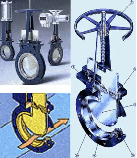
Sea suction valves or cargo suction pipelines and principal problems associated with them are:
1 Leakage – often occurs due to some small pitting on the «V» shaped faces.
2 Cracking of wedge collar – thus the spindle moves up and down, but the wedge stays in place.
In case they are fitted in the discharge side, these valves cannot be used for throttling the flow, as explained before. Each gate valve should be tested for leakage periodically.
A means of regular testing are by shutting the valve and then slowly opening the drain plug fitted below the valve. Alternate, and most reliable means is by pressurizing on one side of the pipeline with air, and checking over a period of time for drop in the air pressure. Valves are operated pneumatically or hydraulically as shown below.
In such a case the shaft spindle should be actuated, and spindle visually observed for its full stroke movement when open and closed from the cargo control room.
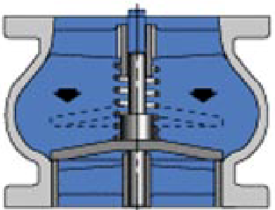
Screw down check valve
A simplified sketch of these valves is shown below. These are usually used as pump vent valves or bleed valves.
Common problems identified with them are:
- Leakage from the valve or seat.
- Sticky operation.
- Seizing/Bending of the spindle.
- Leakage can be tested by pressurizing one side periodically, and testing for oil coming on the opposite side.
- Sticky operation results due to the ball & socket nature of the joint between the valve and the spindle. This is made so in order to allow for any misalignment due to wear on the seat and spindle. A remedy for sticky operation, is periodic inspection and overhaul when required.
- Seizing of the spindles can be prevented by regular operation, in order to prevent rust from accumulating at the moving parts. Often these valves are improperly operated by using wheel spanners which are disproportionate in size for the application. This unnecessary force causes it’s spindle to bend or shear off.
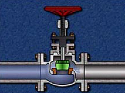
Spring Loaded Globe Valve
A sketch of a Globe valve is shown below.
Common problems are: Breakage of spings, due to corrosion or chattering. This is prevented by regular inspection. Leakage of the valve or the seat – to be kept in check by periodic tests and overhaul.
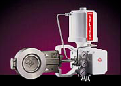
Butterfly Valve: Cross Section shown attached –
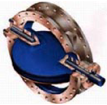
These valves are by far the most common on cargo pipelines.
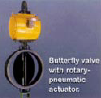
The above figure shows a valve with pneumatic pressure transmitter and a signal indicator, showing how much the valve is open. These can be precisely controlled to adjust the rate of flow.
Valves can be manual, hydraulic or pneumatically actuated. Their advantage lies in their relatively high versatility; it can be used for high OR low pressure systems, compact size using minimum space for fitting, ease of operation & overhaul and virtually full-bore operation/minimum resistance for liquid flow.
Common problems are:
- Failure of the Viton ring seal which seals around the disc edges twisting of the spindle.
- Viton seals are easily available and can be replaced periodically.
- Twisting of the spindle occurs due to forced operation of the valve when the pipeline is heavily pressurised on one side with oil, or lack of frequent operation when the valve disc will seize in place.
Measuring and Control System
Operation of the cargo system is both manually at local stations, and from the cargo control room. In the event of any operational parameters going outside set limits plant will be shut down and cargo operations suspended.
For cargo tanks pressure, level and temperature at different levels are very important parameters and shall be maintained at all times. Each cargo tank is divided in two halves; port and starboard with a bulkhead valve at bottom (0,5 m above tank bottom) and is open at the top. Therefore temperature and level measurements are provided for both sides. The power supply to these control system passes through an intrinsically safe zener barrier.
Cargo Tank Level Gauging
The gauges must be used in conjunction with the tank calibration tables and the correction made for cargoes of varying Specific Gravities. Each cargo tank has one Level Master gauge and one Level switch each on port and starboard side. Level master consists of a float with magnet and a guide pipe with a sensor in the tank. Sensor is fitted with many capsules containing Reed switch and resistors. Float is afloat on the liquid surface, and travel along the guide pipe. According to liquid level change in tank, magnetic flux of float moving upwards or downwards will influence to close Reed switch accordingly. Alarms are given at three different levels with this gauge, they are:
- Low level alarm;
- Before high level alarm;
- Emergency high level alarm (ESDS).
Level readings can be read locally and also in the cargo control console.
Cargo Tank Level Switches
One alarm will normally be at 99 % ie high level. The level switch is top mounted and consists of:
- a guide pipe;
- float;
- terminal box;
- magnets are fixed in the float;
- and Reed switches;
which are located at each alarm point fixed in the guide pipe. When its float rises on liquid to the alarm point, the reed switch opens its contact to give an High level alarm.
Cargo Tank Sample Lines
These are permanently installed sampling points which can be used for sampling of liquid cargo or vapour/inert gas/air concentrations when inerting or purging. On some vessels they may also be used in the event of a level gauge failure for tank level gauging. There are normally three per cargo tank, measuring the levels in the tank bottom, middle and top.
Vapour sampling arrangement for each cargo tank is provided at three different heights. Bottom level, which is 0,5 m from bottom, middle level that is 7 m from bottom and top level which is 15 m from bottom. Vapour sampling can be carried out at the vapour suction line at the trunk top. Vapour is sampled at start of cargo operation and during gas change, inerting, gas freeing etc.
Liquid sampling arrangement is provided at each cargo pump discharge line before discharge valve. Liquid samples are taken by starting cargo pump of the concerned tank.
Reliquefaction Plant
There are many types of reliquefaction systems in use on board vessels and Masters and Officers must consult their Manufacturers Manuals for details of the operation.
The cargo boil off due to heat ingress from air and seawater is re-liquefied and returned to tank by means of re-liquefaction plant. Re-liquefaction system consists of a motor driven compressor that pressurizes the boil off gas from tanks. The high-pressure, high-temperature gas is condensed to high-pressure, low-temperature liquid in the condenser. Seawater is used as the cooling medium. The high-pressure liquid is then expanded to same pressure and temperature as in the tank by expansion valve and returned to the tank. Five sets of Horizontal, opposed piston, 2-stage, oil free, water-cooled type re-liquefaction compressors are provided to maintain tank pressure and temperature. The rated capacity of each compressor is 1 360 cum/hr (gas suction volume), cooling capacity is 220,500 w (for propane), 311,500 w (for butane), delivery pressure of 20 kg/cm2g. The re-liquefaction plant is also used in gas change, tank cool down by top and side spray, hot gassing, pipe cool down at arrival load/disch. port etc. Motor room is separated from compressor room by gastight shaft sealing arrangement. Compressor room is always kept at below atmospheric pressure by 2 exhaust fans, whereas, motor room is kept at higher pressure by 2 supply fans so that any leaked gas in compressor will not flow into motor room.
Cargo Heater
The cargo heater is operated during cargo discharge when a heated cargo is required by the receiving terminal. The heater uses sea water as the heat source. Cargo flows in the shell side of the exchanger and sea water flows in the tubes.
Cargo heater is provided to heat cargo to the shore temperature requirement. The heat exchanger is specially designed for heating of hydrocarbons by seawater. Heater is of shell and tube type with cargo liquid flow through the tubes and seawater flows through the shell. The design prevents freezing of seawater inside the tubes with the risk of tube cracking. The U-tube material is high-alloyed stainless steel with high corrosion resistance against seawater. The tubes are roller expanded and welded to the tube plate. Heater is provided along with cargo booster pumps. The booster pump takes suction from discharge of the main cargo pump and discharges cargo at higher pressure. Two booster pump and one cargo heater are provided. The liquid condition at heater outlet is –5 degrees and rate is 600 cubic per hr. The heating liquid is seawater and care should be taken to avoid freezing of seawater inside the heater. The heater is equipped with 2 off connections (both ends) for draining of seawater and freshwater from flushing after use.
NOTE: In order to prevent freezing of the heater and the associated damage which occurs during freezing, it is essential that the heater is operated at all times with the designed Sea Water flow and that flow is maintained until cargo operations have been Completed and all remaining liquid has been boiled off on completion of cargo operations.
Methanol Injection
Methanol injection piping are led from hose connection valve with strainer (200 mesh) on trunk top to each main cargo pump and emergency cargo pump. Methanol liquid shall be injected to remove the possible freezing on pump shaft bearing (due to water ingress). Methanol injection connection is also provided at inlet of expansion valve of re-liquefaction system to clear the condensate line and also at side and top spray of the condensate line to clear the nozzles.
Auxiliary Equipment and Systems
Hydraulic or Pneumatic Quick Closing System
\
All connections to the tank domes (except for instruments), and shore connections on the manifold cross over lines, are fitted with hydraulically or pneumatically operated, fail safe, ball valves. The system is part of the on-board safety system and causes The Selection and Testing of Valves for LNG Applicationsselected valves to close after release of hydraulic or pneumatic pressure. It also provides the power to activate the valves when operating normally.
Valve Closing Times. The closing time of the valves should be agreed with shore operations, and calculated in accordance with IMO, IGC Code 18.8.2, i. e. The closing time of the valve (i. e. time from shut-down signal initiation to complete valve closure) should not be longer than:
- T = (3,600 × U)/LR seconds, where:
- U = ullage volume at operating signal level in cubic metres;
- LR = max loading rate agreed between ship and shore installation in cubic metres/hour.
The loading rate must be adjusted to limit surge pressure on valve closure to an acceptable level, taking into account the loading hose or arm, the ship and the shore piping system where relevant.
If the pressure in the hydraulic/pneumatic system is released all valves close. This is initiated by the following:
Activating an onboard emergency shut down push-button, or if activated from ashore;
- A fusible plug melting in the pneumatic system, (melting temperature 98-104 °C).
- Instrument air supply failure.
- Electrical power failure.
- Activation of one of the mast blow-off high level switches.
Tank dome valves close if:
- The 98 % full level switch is activated, (many vessels are fitted with an override switch which will prevent the valve from dosing, this override is only to be used with the express permission of the Master).
On some vessels this may be limited to tank filling valves only. This design is not accepted at DOW Chemical Terminals where a separate switch is required which when activated closes all actuated valves on all cargo lines and also stops the cargo pumps.
Air Blower
A separate air blower may also be fitted for the supply of atmospheric air to the purge system. It is connected to the purge line by a spool piece and two non-return valves. The use of the blower may cause condensation at «cold spots», e. g. tank walls and therefore careful drying is a necessity after purgin.
Deck Spray System
The deck spray system is a safety system used for spraying and cooling cargo tank domes, superstructure and housings. Sea water is distributed as follows:
- Exposed cargo tank domes.
- Exposed on deck storage vessels for flammable or toxic products.
- Cargo liquid and vapour manifolds.
Boundaries of superstructures and deck houses normally manned, cargo compressor rooms and pump rooms store rooms containing high fire risk items and cargo control room, all facing the cargo area.
Emergency Shut Down System (ESD)
The emergency shut down system may comprises of two separate systems – an electrical loop with operating buttons located at strategic points on the ship and/or a pneumatic loop containing fusible plugs. The two systems may be interconnected by a pressure switch in the electrical loop.
If the electrical circuit is broken by operation of a push button, or the air pressure drops by the melting of a fusible plug, the following action is initiated:
- lectrical power supply to the gas plant is shut down stopping all pumps, compressors and ventilation systems in the electrical and compressor rooms.
The immediate effect of this action is to release pneumatic pressure and activate the spray system if fusible plugs have melted and the deck spray system is set to «Automatic». This results in the immediate closure of all hydraulically operated valves and shut down of the gas plant.
Hydraulic quick closing system is provided to close all manifold valves simultaneously in an emergency situation leading to activation of ESDS (emergency shut down system).
ESDS is activated under following conditions:
1 Emergency shut down switch is pressed in CBCC.
2 Emergency shut down lever at compressor room front (P & S) is operated.
3 Fusible plug is melted away in fire (98 ~104 degrees).
4 Emergency high level is detected (99,5 % tank level).
5 Control air pressure is less than 0,35 Mpag.
6 Cargo tank pressure decreases to 0,0 Kpag.
7 Electric power source is failed.
8 Service hydraulic oil pressure for valve remote control system falls to below 7 Mpag.
Hydraulic oil accumulators, 5 nos, (hydraulic oil under pressure of nitrogen) are provided for valve closing operation at ESDS situation. Upon Emergency Shutdown System (ESDS) on Liquefied Gas Carriersactivation of ESDS, electric signal is given to ESDS solenoid valves to open and the hydraulic oil accumulators (near port side manifold) release high-pressure oil to all 12 nos manifold valves to shut. All the valves are shut within 30 sec. The system can be returned back to normal only upon rectifying the cause.
Fixed Gas Detection System
A fixed gas detection consists of a series of sensors, alarm module and measuring unit situated in the cargo control room or on the bridge continuously monitoring the concentration of gases in the specific areas of the vessel.
The gas detection system must always be in operation when the cargo tanks or gas plant contain cargo. The system must be checked regularly for correct operation, and it must be reset whenever a new cargo is introduced.
Read also: Ship-to-ship LNG transfer operations
Fixed gas detection system is provided to detect any leakage of cargo in early stages. Fixed gas detection system is provided for cargo part and accommodation part. Cargo part gas detection system has sensors placed in each hold spaces port and starboard, motor room and compressor room. Accommodation part gas detection system has sensors placed at:
- A-deck accommodation entrances;
- general office;
- galley;
- ECR;
- officers smoke room;
- crew smoke room;
- cargo instrumentation room and inside cargo part gas detection panel.
The cargo part gas detection system works on principle of NDIR (Non-dispersive infrared analyzes), has a measuring range of 0 to 100 % LEL, is set to give an alarm at 10 % LEL. It continuously sucks sample from all points but only one sampling point is selected at a time for analysis whereas others are given to atmosphere by by-pass pump.
Sampling points are changed over automatically every 2 minutes. An audio and visual alarm is given if alarm condition exists. The accommodation part gas detection system works on the principle of catalytic combustion, has measuring range of 0 to 100 % of LEL set to give an alarm at 30 % LEL.
THE SYSTEM MUST BE SPAN CHECKED ONCE IN TWO MONTHS All checks and changes to settings must be recorded in the Log Book.
Toxic/Flammable Gas Detection. Detectors may be installed in the air conditioning system intakes or at different locations inside accommodation space/ Instrumentation room to monitor the presence of toxic gases, e. g. vinyl chloride, ammonia. These will detect concentrations of gas in air down to 2 ppm.
The instruments and controls are normally housed in the cargo control room. The recommended alarm levels are 10 ppm for vinyl chloride and 50 ppm for ammonia.
Equipment Condition Monitoring
To maintain the efficiency of the plant the condition must be monitored on the daily basis as per daily maintenance log of cargo equipments. Main monitoring station for cargo handling system is located in the cargo & engine control room. Also the conditions of each tank such as temperature, pressure etc. can be monitored from wheelhouse. Alarms are classified into individual alarm group and group alarm. The group alarms are divided into three groups.
- Trouble alarm for cargo handling system.
- Trouble alarm for re-liquefaction plant.
- Trouble alarm for cargo containment system.
The watchman station can be selected between LPG officer and CBCC (Cargo & Ballast Control Console). At watch position LPG officer, if a alarm sounds an audio and visual alarm will come at all group alarm stations in accommodation and also on VDU at CBCC and Bridge. At watch position CBCC, if any alarm comes it will give audio and visual indication at CBCC only. At the VDU any group display can be selected to observe the parameters at any given point of time. Also display can be made available in graph form or trend form. History of last 50 alarms is available and summary of all active alarms is also available.