This article discusses certain methods of calculating shipped quantities of liquefied gas cargoes. It aims to explain the main points of difference between calculations for liquefied gas and other petroleum cargoes.
- Principles for Liquefied Gases
- Special practices for gas cargoes
- The difference between before and after quantities
- General – density in air and density in a vacuum
- Gas-up and cool-down quantity calculation
- Shore terminal considerations
- Taking Samples of Liquefied Gas Cargoes
- Why cargo sample are taken
- Sampling systems – “open loop” or “dosed loop” systems
- The procedures involved in taking samples
- Measurement of Cargo Tank Volumes
- Trim correction
- List correction
- Tape correction
- Float correction
- Tank shell contraction and expansion
- Measurement of Density
- Density measurement methods
- Ship/Shore Calculation Procedures
- Outline of weight in air calculation
- Procedures using standard temperature
- Example – LPG Cargo Calculation
- Other Calculation Procedures and Measurement Units
- LNG Quantification
- Example of contractual requirements for the measurement of the energy transferred at an LNG unloading terminal
- Cargo Documentation
The difference in cargo calculations between LNG (based on energy content) and other liquefied gas cargoes (combined sum of masses of cargo liquid and vapour) is also discussed.
Principles for Liquefied Gases
Special practices for gas cargoes
The inclusion of vapour in cargo calculations
Liquid cargoes are generally quantified by measuring the volume accurately and multiplying it by the density of the cargo. For petroleum products, the amount of hydrocarbons in the vapour space of the tank is not significant and is ignored in the cargo quantification process. Liquefied gas cargoes are boiling liquids in equilibrium with their vapours in the dosed containment system, with the vapour above the liquid cargo in the tank wholly comprised of the cargo itself. No vapour is lost from the system, but it may condense back into the liquid or liquid may evaporate (see article “Properties of liquefied gases
Saturated vapour pressure (SVP)“). The quantity loaded, therefore, exists partly as liquid and partly as vapour, and it is necessary to account for both in the cargo calculations.
The difference between before and after quantities
During discharge, some of the liquid cargo may be evaporated to maintain tank pressures and so this amount of product remains on board. Further, it is common practice in some trades to retain on board a significant quantity of liquid (heel) and its associated vapour to keep cargo tanks cool on the ballast voyage and to provide suitable cargo quantities for cool-down before loading the next cargo. On loading, the new cargo is commingled with the heel. Alternatively, if the ship has arrived with warm tanks, bulk cargo may be added to the volume of cargo taken on board for tank cool-down purposes. In both cases, where reliquefaction plants are in use, some of the vapour is converted to liquid as part of the process of managing tank pressures. Therefore, to determine the amount of cargo discharged or loaded, it is necessary to measure the vapour and liquid quantity both before and after handling.
Temperature and liquid level measurement
Cargo loaded in a ship’s tank may vary in temperature across the loading period. This may be due to cargo coming from different shore tanks or to the initial cooling of shore pipelines. Liquefied gases have comparatively large thermal coefficients of volumetric expansion, which are three to four times those of petroleum products. Therefore, the resulting variation in density of the cargo may give rise to stratification in a ship’s tank after loading. A number of temperature sensors are usually provided at different tank levels and it is important that all these temperature readings are taken into account to assess accurate overages for the liquid and vapour. It is from these overage temperatures that the appropriate temperature corrections may be applied.
A tank’s liquid and vapour content will adjust to saturated equilibrium, either by boil-off or by condensation. However, this equilibrium may not be achieved immediately after loading. For the sake of accuracy, it is, therefore, desirable to delay cargo measurement and sampling for as long as possible, subject to the constraints of the ship’s departure time.
Liquefied natural gas (LNG) cargoes
LNG cargoes are handled differently from other liquefied gas cargoes, as the basis of bulk LNG transactions is the energy or calorific, content of the cargo. The principles underlying LNG cargo measurement are similar to those for other liquefied gas cargoes, except that there is a need to convert mass to calorific content (see article “LNG Quantification” below).
General – density in air and density in a vacuum
The terms “weight” and “mass” are often used interchangeably, but this is not correct. The mass is the amount of matter in any given object, while its weight is the force exerted by gravity on the object. The mass is a characteristic of an object, which means it would be the same in space (ie zero gravity) as on earth, while weight depends on the force of gravity where the object is placed.
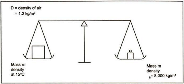
Everyday commodities, such as fruit or cement, are sold by weight, which means their weight-in-air. Weighing is carried out by balancing the force of gravity acting on an item against the force of gravity acting on a known mass – for example a brass weight when used on simple balance scales. Since the gravitational force is the same on both sides of the balance the weighing process is balancing mass against mass.
However, because the item and the brass weight are immersed in air during this process, the Archimedes’ principle tells us there will be a small upthrust. The upthrust is equal to the force of gravity acting on the mass of air displaced. So, if the commodity and the weight occupied the same volume the buoyancy upthrust would be the same and the result would be a mass to mass balance. The same would apply if the weighing was carried out in a perfect vacuum, which means that the term “weight-in-vacuum” is synonymous with mass.
Read also: Overview of the Carriage of Liquefied Gases by Sea
Typically, the volume of the item being weighed on the beam balance will be different to the volume of the brass weights, which means there is an imbalance in the buoyancy forces on either side of the balance. This is usually ignored as it is so small, but it does mean that the weight of a commodity determined by this method will be slightly different to its actual mass. To minimise the effect of buoyancy variations, balance weights are standardised against brass that has a density of 8 000 kg/m3. Therefore, the use of balance weights made of a different material does not matter as all balance weights are calibrated against this brass standard to compensate for the different buoyancy.
Variation in the gravitational field has no effect on the result as the variation affects both sides of the balance equally, so the result is independent of the type of machine used in its location. However, if a machine calibrated under one gravitational field is relocated to an area with a different gravitational field, the results will be incorrect unless it is recalibrated.
True density (weight in a vacuum)
There are two important points to note when applying this indirect method. Density should be quoted in the fundamental units of mass per unit volume, called “true density“, which is the weight per unit volume in a vacuum. Therefore, an adjustment for the buoyancy of air is necessary to obtain the weight in air.
Apparent density (weight in air)
The “apparent density” of a substance is the weight per unit volume in air. Both densities are quoted in the same units (eg kilograms per cubic metre) but, as cargoes are traded by quantity in air or quantity in vacuum, it is essential to clearly specify the type of density (true/apparent).
Relative density (specific gravity)
The density of a substance relative to that of pure water is also an important unit in the gas industry. This is called the “relative density” or “specific gravity“. Again, buoyancy and the fact that the water may be at a different temperature to the substance under consideration must be accounted for.
The relative density or specific gravity of a liquid is the ratio of the weight in a vacuum of a given volume of that liquid at a specified temperature to the weight in a vacuum of an equal volume of pure water at a specified temperature. When this ratio is reported the reference temperatures must also be stated. For example, relative density 15 °C/20 °C means the ratio of the true density of the liquid at 15 °C to the true density of water at 20 °C. As it is a ratio, there is no unit for relative density.
Apparent relative density (apparent specific gravity)
The “apparent relative density” or “apparent specific gravity” of a liquid is the ratio of the weight in air of a given volume of that liquid at a specified temperature to the weight in air of an equal volume of pure water at a specified temperature. When this ratio is reported the reference temperatures must also be stated. For example, apparent relative density 15 °C/20 °C means the ratio of the apparent density of the liquid at 15 °C to the apparent density of water at 20 °C.
The volume of the cargo is very important and this, in turn, depends on its temperature. Therefore, it is necessary to specify the conditions at which the cargo is to be quantified. The condition most commonly chosen is to evaluate the cargo as though it was at 15 °C and it is further assumed that the entire cargo is a liquid at its Boiling Point – Definition and Pronunciationboiling point.
This is why it is essential to state clearly the standard condition assumed for the cargo quantification. Although the mass of two cargoes may be identical, if their volumes are not equal the upthrust caused by air displacement will be different and so their weight will be different. An extreme case could be conceived where two cargoes of equal mass were weighed, one entirely as a liquid and the other entirely as a vapour. The liquid would have a weight not greatly different in magnitude from its mass, while the vapour would have very little weight due to its very large air displacement. The use of a precise standard avoids this ambiguity.
The derivation of cargo weight may be carried out, in practice, by two methods. The mass may be calculated and converted to weight by use of a conversion factor, with the liquid density at 15 °C. The conversion factor used in this method is provided in the American Petroleum institutes (API), “Manual of Petroleum Measurement Standards (MPMS)” (Reference 2.65).
The following equation expresses the relationship between density in vacuum in kg/3 at 15 °C and density in air at 15 °C in kg/m3:
where:
- Da15 = Density in air;
- D15 = Density in vacuum.
The second practical method of determining the weight of a cargo is from its volume at 15 °C using a volume to weight conversion factor. The weight conversion factor is the weight per unit volume of the saturated liquid at 15 °C and it should not be confused with density, although it is closely related. The factor has a unit of weight per unit volume, while true density has a unit of mass per unit volume. The American Society for Testing and Materials (ASTM) Standard D1 250-08 (refer to Table 1) gives the relationship between density at 15 °C and this volume to weight conversion factor (see Reference 2.64).
| Table 1. Extract based on ASTM D1 250-08 Density/Weight/Volume intraconversion Part 3 “Conversions for Absolute Density at 15 degrees C” (This is similar to the old ASTM Table 56 1980) | |||
|---|---|---|---|
| Density at 15 °C (kg/I) | Factor for Converting Weight in Vacuo to Weight in Air | Density at 15 °C (kg/I) | Factor for Converting Weight in Air to Weight in Vacuo |
| 0,5000 to 0,5191 | 0,99775 | 0,5000 to 0,5201 | 1,00225 |
| 0,5192 to 0,5421 | 0,969785 | 0,5205 to 0,5432 | 1,00215 |
| 0,5422 to 0,5673 | 0,99795 | 0,5433 to 0,5684 | 1,00205 |
| 0,5674 to 0,5950 | 0,99805 | 0,5685 to 0,5960 | 1,00195 |
| 0,5951 to 0,6255 | 0,99815 | 0,5961 to 0,6265 | 1,00185 |
| 0,6256 to 0,6593 | 0,99825 | 0,6266 to 0,6603 | 1,00175 |
| 0,6594 to 0,6970 | 0,99835 | 0,6604 to 0,6980 | 1,00165 |
| 0,6971 to 0,7392 | 0,99845 | 0,6981 to 0,7402 | 1,00155 |
| 0,7393 to 0,7869 | 0,99855 | 0,7403 to 0,7879 | 1,00145 |
| 0,7870 to 0,8411 | 0,99865 | 0,7880 to 0,8421 | 1,00135 |
| 0,8412 to 0,9034 | 0,99875 | 0,8422 to 0,9044 | 1,00125 |
| 0,9035 to 0,9756 | 0,99885 | 0,9045 to 0,9766 | 1,00115 |
| 0,9757 to 1,0604 | 0,99895 | 0,9767 to 1,0614 | 1,00105 |
| 1,0605 to 1,100 | 0,99905 | 1,061 to 1,1000 | 1,00095 |
Liquefied gases are always handled in closed containers from which air is totally excluded. Consequently, air has no influence on either the liquid phase or the vapour phase of the stored product.
While, from a purely scientific point of view, it is not correct to use apparent densities in quantity calculations, they are applied in the commercial trade of liquefied gases. An apparent density of a liquefied gas should be considered as a theoretical density. It may be obtained from a true density, converted to apparent density by applying the correction factor in the API MPMS (Reference 2.65).
Densities of the most common liquefied gases at their boiling point vary from 0,5680 kg/litre (ethylene) to 0,9714 kg/litre (vinyl chloride monomer (VCM)). When converting this true density to density in air (apparent density), a difference of 0,0011 kg/litre will always a rise. Note that conversion from density in air to density in a vacuum has to be done by introducing the conversion factors from the API MPMS, with a density at 15 °C. This conversion is not always possible considering the critical temperature of products such as ethylene or methane, which are completely gaseous at 15 °C.
In 2009 the API released ASTM D1 250-08 (Reference 2.64), which is the PC based equivalent of the previous volume X of ASTM D1 250-80.
This PC programme gives calculation procedures, but there are no tables. This new standard is based on equations and is intended to replace the printed tables of the MPMS.
The ASTM D1 250-80 table value shows, on average, a value that is 0,0020 % higher than the new ASTM D1 250-08 standard value.
Many of the ASTM D1 250-80 tables are in use worldwide and their use will continue in some cases for the foreseeable future as agreements between seller and buyer and governmental requirements exist.
Further details are available in the technical paper “Comparison of ASTM D1 250-08 & 80” by QuantityWare GmbH (Reference 2.66). This paper provides a comparison between density in air and inverse density in air values of the most commonly used ASTM D1 250-80 tables and the corresponding ASTM D1 250-08 formula values.
Gas-up and cool-down quantity calculation
Liquefied gas carriers proceeding from a drydock or repair yard to a loading port need to displace the inert gas or nitrogen in the ship’s cargo tanks by “gassing-up” with cargo. With the exception of gas carriers carrying the cargo at ambient temperature, it will also be necessary to spray and cool-down the ship’s tanks to an acceptable minimum temperature before they can be loaded.
The quantity of liquefied gas required for gas-up and cool-down may be calculated using alternative methods:
- A Gassing-up Certificate may be provided by the ship builder. The certificate references the total volume of the cargo tanks, the assumed values for the required number of vapour replacement cycles, using displacement purging, and the temperature and density of the purge gas. These assumed values are used to determine the quantity of liquefied gas required for the atmosphere in all tanks to reach the required hydrocarbon content and, where applicable, the maximum allowable CO2 limits for loading. For LNG ships the certificate will provide both an assumed composition and the higher heating value for the LNG supplied from the terminal to calculate the total energy quantity of the LNG required.
- Cool-down tables may also be provided by the ship builder, which detail the quantity of liquefied gas required to lower the tank temperatures from ambient to the temperature required for loading. The average temperature of the ship’s tanks at the start of the cool-down operation are entered to determine the quantity of liquefied gas required to achieve the average tank temperature considered acceptable for loading. The calculations used to determine the tabulated cool-down quantities consider the overall tank surface area, the overall heat capacity of the cargo containment system for a stabilised temperature gradient across the tank insulation and the latent heat of the vaporised liquefied gas. For LNG ships the cool-down tables express the quantity of LNG required in millions of British thermal units (MMBTU) and assume a standard LNG composition. More than one set of tables may be required to cover a range of LNG compositions at different loading terminals.
In the absence of cool-down tables an estimate of the liquefied gas quantity used during cool-down can be calculated by referencing the pressure/flow curves of the cool-down nozzle, if available, and using the average spray header pressure to determine the throughput of the nozzle. The throughput, duration and number of spray nozzles can then be used to estimate the quantity of liquefied gas used during the cool-down.
A quantity of heavy ends, butane, propane and ethane may precipitate out during the cool-down of LNG tanks. These heavy ends re-combine with the heel when the tank is fully cooled down and are not quantified separately.
For terminals that use flow meters for custody transfer measurement, the flow rates required to supply the ship’s vaporiser for gassing-up and tank spray rails for cooling down may be below the acceptable limits for accuracy of the in-line flow meters.
Shore terminal considerations
Terminals usually require storage tanks to be measured for day to day internal accounting. However, shore tank measurements for cargo loaded or received are not always as accurate as ship measurements.
The shore storage tanks usually have greater cross-sections than the ship’s tanks, so there can be greater inaccuracies associated with onshore liquid level measurement, particularly in the transfer of small cargoes.
Figure 2 shows an arrangement of a terminal where two tanks are used for the storage of refrigerated product. One tank may be used to service the ship that is loading while the other receives product from the production plant. Before cargo transfer, the loading line to the ship is usually cooled down by recirculating cargo to the jetty and back to the tanks.
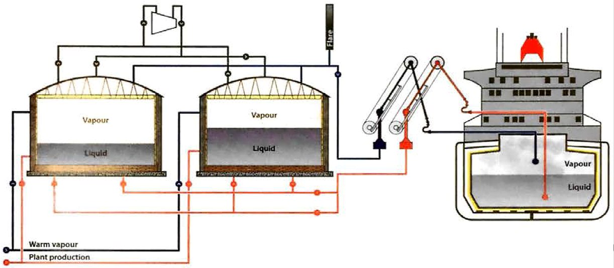
A reliquefaction system is provided to maintain the pressure in each tank to within specific limits. Warm vapour con be supplied to each tank to prevent the possibility of a vacuum in the shore system.
Figure 2 shows that the reliquefaction system is common to all shore tanks. Vapour may, therefore, be interchanged between tanks. When the product is being run down from the production facility to one of the tanks, the rise in liquid level will force vapour out and into the common header compressor intake. Liquid from the shore tank being discharged will need to be replaced by vapour, which can come from several sources. Similar vapour movements are also possible within the ship.
Figure 2 also illustrates that the vapour and liquid movements ashore, or between shore and ship during the loading or discharging of a gas carrier, are quite complex and depend on the rate, the temperature and the nature of the product that is transferred.
Ship/shore quantity comparison is relevant provided that:
- proper calibration of both ship and shore tanks is available;
- the shore tank(s) is (are) isolated from other terminal arrangements, such a s shore flare, production units, truck or railcar loading;
- the liquid line system from the shore tank to the ship’s manifold is full before and after loading;
- the temperature of the product (ie density) in the shore line is the same as in the shore tank, both before and after loading;
- no vapours are released from the ship’s cargo tanks to the shore flare, except when an accurate flowmeter is available.
When a ship is loading liquefied petroleum gas (LPG) or chemical gases, the vapour displaced is normally reliquefied by the ship’s plant to keep tank pressures within safe limits and to prevent venting. A vapour return may be connected to allow vapour to flow from the ship back to the shore. This vapour return may be directed to the shore tank being discharged, although provision is also made to flare this vapour if it is of unacceptable quality or in an emergency.
For ethane, ethylene and LNG cargoes, it is industry practice to use a vapour return line when transferring cargo.
If the loading rate is such that the ship’s reliquefaction plant can cope with any vapour generated, it is possible to load without the need for a vapour return line. This minimises the vapour movements around the system, so comparison between ship and terminal figures is simplified.
There may be greater discreponcies between ship and shore figures when large vapour movements occur, such as when a vapour return line is used. To overcome these problems the use of an accurate flow metering system, that measures the liquid to the ship and any vapour returned, is the only possible solution.
It is usual for cargo interests to appoint an independent cargo surveyor as an unbiased third party to verify the ship and shore volume measurements, the use of appropriate density values and the cargo calculations.
Taking Samples of Liquefied Gas Cargoes
In the liquefied gas shipping industry, cargo sampling is a common requirement that is part of the routine quality control and custody transfer procedures. As any sampling point potentially exposes the operator or environment to flammable and/or toxic liquid or gases, the IGC Code includes requirements for the design and operation of sampling systems to minimise the release of liquid or vapour.
Provided that proper procedures, established on both ship and shore, are carried out by competent personnel familiar with the operation, and that they use fully compatible equipment that is suitable for the task, the risks associated with taking liquefied gas samples should be minimal. Should these requirements not be met, however, experience has shown that the possibility of an incident will increase significantly. The most typical example of this situation is the requirement for shore representatives to draw samples from ship tanks.
Why cargo sample are taken
Sampling is carried out for two basic reasons:
- To confirm that conditions are in accordance with requirements prior to cargo transfer.
- To confirm that the cargo is within commercially agreed specifications at the point of custody transfer.
For certain cargoes the requirements for conditions “prior to transfer” are stated in the IGC Code. For example, before loading butadiene the oxygen content in the cargo system must be below 0,2 %. In other circumstances there may be a specific requirement agreed between supplier and receiver.
Supplier/receiver agreements can vary widely, depending on prevailing production specifications and an individual customer’s requirements. Therefore, any variations and stipulations regarding the number of samples required and receiving tank conditions are commercial matters for the contracting parties to agree upon.
It should be noted that sampling requirements for the same product may differ significantly. Many consignments of butane are carried as fuel gas and the prime concern is calorific value, but other butane cargoes may be destined for cavern storage where the specification states a maximum methanol content, or may be intended for aerosol propellant, which will require a high degree of purity. It is in the interests of all parties, therefore, that conditions and requirements are made known to those responsible for storage, transfer or carriage of the cargo.
The extent of sampling should always be minimised by proper cooperation so that agreed representative samples are taken and the analysis results are accepted by all parties. The use of automatic sampling devices in terminal loading systems may further reduce the need for manually drawn samples.
Sampling systems – “open loop” or “dosed loop” systems
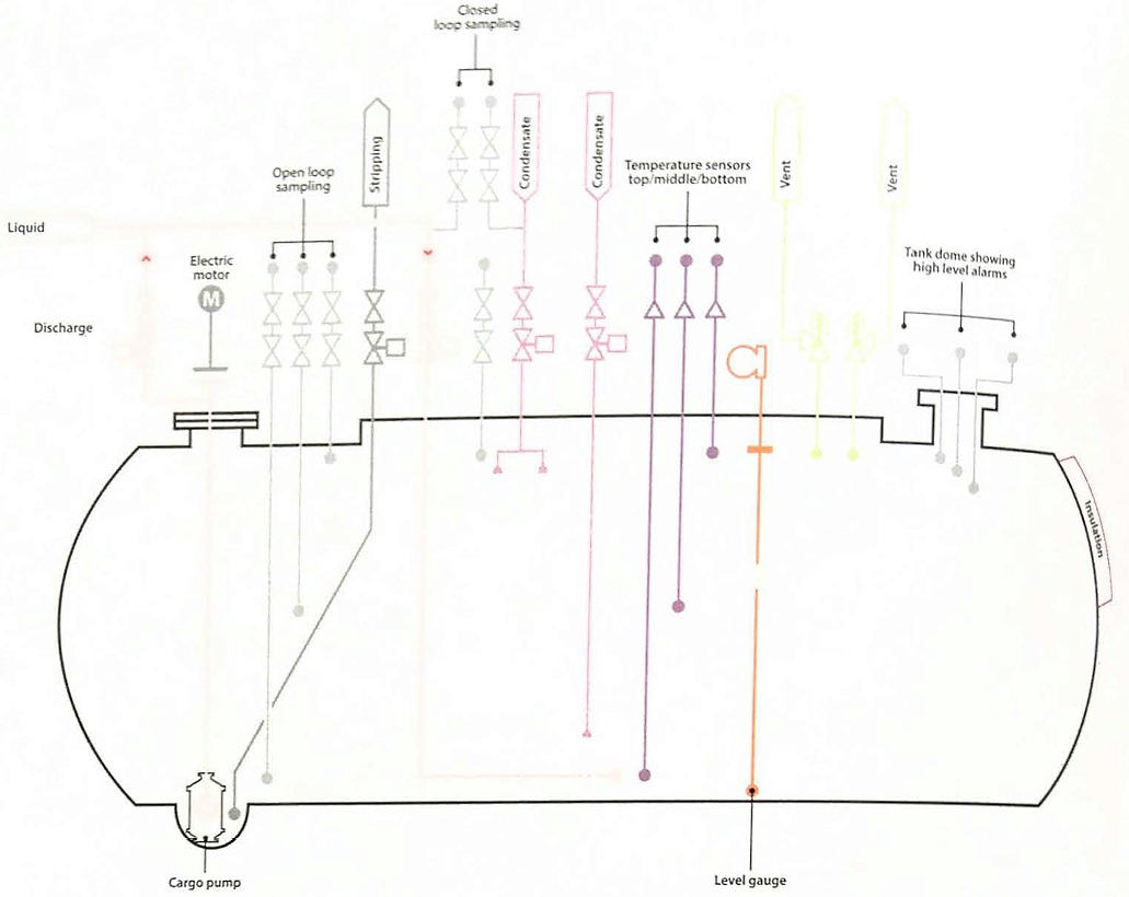
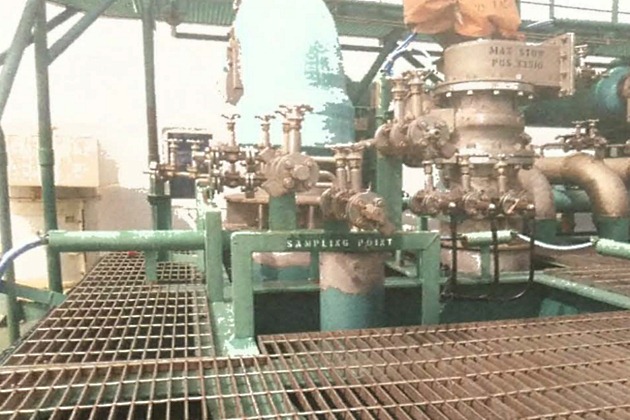
Ships’ cargo tanks are normally fitted with several sample connections so that samples may be taken at different tank liquid levels. “Top“, “middle” and “bottom” samples are common and these are of great assistance when checking vapour displacement operations, such as “inerting” or “gassing-up“.
The lower connections can also be used to take liquid samples if there is a suitable pressure in the cargo tanks. This is not possible with fully-refrigerated cargoes, where it is necessary to take samples using the cargo pump, usually recirculating product back to the same tank.
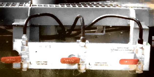
(Note that the second valve is not shown)
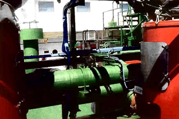
Liquid sampling connections will usually be fitted with two valves to ensure isolation if one is blocked by ice or hydrates, etc., and they will terminate in a standard connection.
During sampling, venting to atmosphere will normally be minimised, although it is recognised that a small, controlled amount of cargo vapour may be released during purging of sample points and when creating an ullage (vapour space) in sample containers. Any such purging or venting of sample containers must be carried out in a safe location, taking into account the properties of the product, wind and weather conditions and proximity of sources of ignition and ventilation intakes, etc.

If the sample system has only an inlet connection to the sample container, it will always be necessary to vent small quantities of cargo to atmosphere. This is known as an “open loop” system.
If a second connection is provided so that product can be returned to the cargo tanks, this arrangement is known as a “closed loop” system and, if used with a sample container with inlet and outlet connections, it minimises the amount of product vented to atmosphere.
The return path of this closed loop will usually also be fitted with double shut-off valves, which should normally be operated full open or closed and not be used for throttling/flow control during the sampling process.
Examples showing “closed loop” sampling systems, on both semi-refrigerated and refrigerated ships, are shown in Figures 5 and 6.
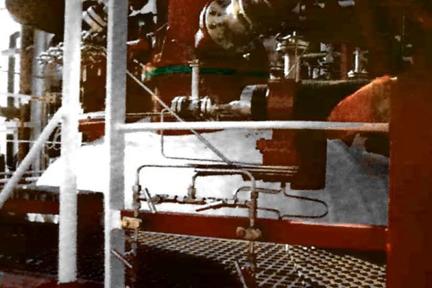
Liquid samples of toxic cargoes on LPG carriers not fitted with a closed loop system should normally only be taken after a specific risk assessment, to consider how to disperse the cargo vented to a safe area, has been carried out. The alternatives to be considered include connecting the sample container outlet to the vent mast, or even to another sample container in cascade. For ammonia sampling, the vapour displaced could be passed by hose to a water surface or spray, but precautions should be taken to prevent water being drawn back into the sample container due lo the extreme solubility of this cargo.
Alternatively, vapour samples could be taken instead of liquid samples, but these may not be representative of the bulk cargo.
Certain cargoes, such as propylene oxide, are required by the IGC Code to be carried under a nitrogen blanket. Product samples are, therefore, only drawn from the liquid phase.
The vapour space is sampled to ensure adequate nitrogen content. Further advice is available from the IGC Code and the safety data sheets (SDS) for the cargo concerned.
The procedures involved in taking samples
Whenever sampling is undertaken, it may be useful to refer to the safety guidance given in the ICS “Tanker Safety Guide (Liquefied Gas)” (Reference 2.68), SIGTTO‘s “Liquefied Petroleum Gas Sampling Procedures” (Reference 2.67) and ISO 4257 (Reference 2.69), particularly regarding the use of protective clothing, gloves, goggles, breathing apparatus and “certified safe” electrical equipment. Sampling of toxic cargoes may require additional specialised equipment. Written procedures for sampling all cargoes included in the ship’s Certificate of Fitness should be part of the ship’s cargo operations manual.
It is imperative that everyone involved in sampling operations is properly informed of the nature of the cargo being handled and the precautions to be observed. This information should, for example, include a full description of the physical and chemical properties of the cargo, counter measures against accidental personal contact, fire-fighting and other emergency procedures. The SDS and any other sources, such as hazardous chemicals (HAZCHEM) or transport emergency (TREM) cards from the terminal or the IGC Code should be consulted for this information.
It is prudent to have a Responsible Officer present at all times when any sample is drawn from a ship’s cargo tanks by a terminal representative or third party inspector. The Officer will need to be fully conversant with all aspects of the ship’s sampling system, including the operational characteristics of all valves. The Officer will need to ensure that sampling is authorised and permitted to be carried out, and actually carried out, in a safe manner regardless of who is actually performing the sampling operation.
Before starting any sampling operation the Responsible Officer will satisfy himself that the equipment to be used during the process is fully compatible with the ship’s sampling points, paying particular attention to the compatibility of threaded connectors.
Care should be taken to ensure that no attempt is made to force a tapered male thread into the ship’s sampling, connection.
For commercial purposes it is imperative that the sample is representative of the cargo in the ship’s cargo tanks. To help to ensure this, it is common practice to recirculate cargo within the tank to be sampled for 10 to 20 minutes, using a cargo pump, before a sample is taken. If taking samples shortly after liquid loading has commenced, it is considered essential to ensure that there is sufficient cargo in the tank for the cargo pump to operate safety.
Sample containers will need to be completely clean and purged with nitrogen or helium before use. For the sample to be representative, the container has to be purged thoroughly with cargo from the sampling connection. For refrigerated cargoes, sufficient cargo has to be passed through the container to cool it down to liquid temperature.
Care should be taken not to spray any cargo directly onto the ship’s steel structure to avoid the risk of brittle fracture. It should also be noted that any liquid released from on ambient temperature sample container will cause a drop in temperature due to the Joule-Thomson effect (see article “Gas laws, thermodynamic principles and reliquefactionDirect cycle“).
If the cargo is a mixture of different products, the lighter components will evaporate more rapidly than the less volatile fractions, with the potential of obtaining an unrepresentative sample. This can be overcome by using “closed loop” sampling or by carefully turning the sample container, so that the vent valve faces downwards during cool-down, to drain off any liquid that collects.
It will be interesting: Ship/shore interface for safe loading and unloading of LNG/LPG
When a sample is taken the primary valve on the inlet will be fully open, with any throttling/flow control carried out at the secondary valve. For “closed loop” sampling, the valve(s) on the outlet will be fully open.
On completion of sampling the practice is to ensure that sufficient ullage or vapour space is left in the sample container to allow for liquid expansion due to the temperature increasing to ambient. Proper ullage can be established if the sample container is fitted upright (ie ullage tube at the top) and is filled from the bottom connection. The container should usually then be vented carefully through the ullage valve until only vapour is emitted.
Due core should be taken to ensure this ullage is established correctly if a “closed loop” sampling system is used.
Points worth remembering when sampling liquefied gas cargoes:
- bursting disks are designed to rupture if the ullage space in the sampling cylinder is less than 5 %;
- sampling cylinders should usually be fitted with an ullage tube that is designed to reduce the possibility of overfilling (normally allowing an ullage space of approximately 20 % to be achieved).
Overfilling can occur if the cylinder:
- is not fitted with an ullage tube;
- or is not filled in the vertical position;
- or is connected to the sampling point upside down, with the ullage tube assembly at the bottom;
- or the ullage tube is not “vented“.
Further information on this subject is available in “Liquefied Petroleum Gas Sampling Procedures” by SIGTTO (Reference 2.67).
Measurement of Cargo Tank Volumes
Calibration tables
All ships should be provided with a calibration table for each cargo tank. The calibration table enables liquid and vapour volumes to be found from a measurement of the liquid level. A calibration table is obtained from careful measurements taken at ambient temperature and pressure after the ship is built. The volumes given in the tables normally assume the ship to be upright with no trim. The calibration tables, therefore, contain correction factors with which to adjust the liquid level measurements in accordance with the actual conditions of the ship’s list and trim and with the cargo tank temperatures at the time of cargo measurement.
Tank inventory
The determination of a tank inventory is the first stage in calculating a cargo quantity and is based on the measurements of liquid level, liquid density, liquid temperature, vapour space temperature and vapour space pressure. Corrections for trim, list, shrinkage, tape, etc., are then applied depending on the type of liquefied gas carrier.
Temperature is extremely important and a reliable figure needs to be established for both the average liquid and the average vapour temperature. This is most accurately achieved using a correctly calibrated multipoint platinum resistance thermometer. The readings of all liquid and all vapour temperatures will be averaged to determine the resultant values. The vapour space may show significant variation between the temperature near the liquid surface and that near the top of the tank. Therefore, an average temperature is taken for calculation purposes:
- Read the temperature profile to calculate an average liquid temperature and an average vapour temperature. The average liquid temperature is the arithmetic mean of all temperature points within the liquid and the average vapour temperature is the arithmetic mean of all temperature points within the vapour, so long as the tank is of constant cross-section. Where the cross-section changes a volume weighted average temperature should be calculated.
- Read the cargo tank pressure.
- Read the liquid level.
Trim correction
Figure 9 shows a prismatic tank on a ship that is trimmed by the stern (ie the ship’s aft draught is greater than the forward draught). With the ship in the trimmed position the liquid level in the tank remains horizontal and the liquid level rises by the amount a/a’ at the aft bulkhead. However, if the ship was on an even keel (or zero trim), the liquid level would be as shown by the dashed line on the diagram.
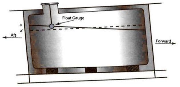
It is usual for tank calibration tables to be presented assuming that the ship is on an even keel. Therefore, where the tank gauge is not situated at the tank’s geometric centre, and if the ship is trimmed, a correction to the measured liquid level must be applied to enter the calibration table at the correct value to obtain the correct liquid volume.
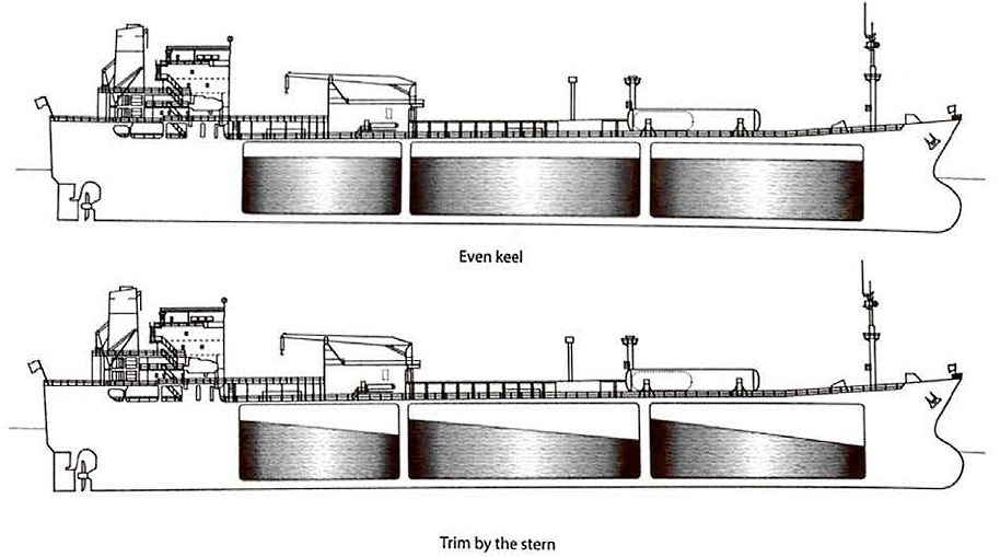
This deviation from the correct liquid level is the distance between the gauge float and the even keel liquid level.
List correction
Figure 11 shows a prismatic tank on an LPG carrier with a partial centreline bulkhead that is listed to port (ie the ship’s port side draught is greater than the starboard side draught). With the ship in a listed condition the liquid level in the tank remains parallel to the waterline. Therefore, and taking the port side tank as an example, at the outer bulkhead the liquid level rises by the amount a/a’ (and he the liquid level at the outer bulkhead on the starboard tank is lowered by the amount b/b’, with the amounts a/a’= b/b’). However, if the ship was upright, the liquid level would be as shown by the dashed line on the diagram.
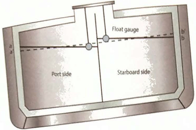
(As viewed from astern. Note the centreline bulkhead valve is closed)
It is usual for tank calibration tables to be established assuming the ship to be upright (having a zero list). Where the tank gouge is not situated centrally, and if the ship is listed, a correction to the measured liquid level is necessary to enter the callibration table to get the correct liquid volume. This deviation from the correct liquid level is indicated on the diagram by the distance between the gouge float and liquid level shown for the ship in the upright position.
Tape correction
A temperature correction is applied to compensate for the change in vertical position of the gouge relative to the tank bottom. As the float gauge tape passes through cold vapour space, it will control (shrinkage) accordingly. A correction due to the temperature is made against a certified standard gauge temperature. The correction is a function of the length of the tape exposed to the vapour space and the temperature of the vapour space.
Float correction
The immersion of the float in the liquid cargo depends on the cargo density (Archimedes’ principle). The zero reading of a float gauge is determined by the manufacturer, based on a cargo specification at the design stage, and is normally at 50 % float immersion. If the cargo liquid has a temperature and density different from that assumed for the manufacturer’s zero determination, a small correction for float immersion will be required.
Tank shell contraction and expansion
The calibration tables usually have a temperature correction factor to account for the fact that, when a tank is cooled, the contraction of the material changes the tank volume compared to the ambient temperature calibration measurement. If the liquid temperature is different from the vapour space temperature it is usual to apply separate correction factors to the liquid and vapour space tank volumes.
Measurement of Density
Density measurement methods
Except for pure products such as ammonia, ethylene, propylene (polymer grade), vinyl chloride and butadiene, where density tables are readily available, products are a mixture of different components and will require their density to be measured. This measurement requires laboratory equipment that is generally not made available on ships, so cargo liquid density is measured on shore and the results are provided to the ship for its cargo calculations.
There are four principal methods of liquid density measurement:
Calculation from an analysis of liquid composition
Selection principles LNG samples and temperature on tankersLiquid composition analysis is the most accurate method of density measurement and is increasingly used in terminals. The liquid composition is normally determined from gas chromatograph readings. The density is calculated from this analysis using one of two formulae; either the Francis Formula or the Costald Equation. The Francis Formula is simpler but is applicable only to LPG temperature ranges and loses some accuracy in LPG mixtures and chemical gases. The Costald Equation is more complicated but provides more accurate results when calculating the density of LNG, chemical gas and mixed gas cargoes. Calculations using these formulae are usually carried out by a computer.
Apart from the greater accuracy obtainable by these formulae, the methods also have the virtue of providing a density at any required temperature without introducing the inaccuracy of generalised conversion tables.
Density meters
Shore tank density may be measured by density meters that use a number of different physical principles:
- differential pressure across the height of a known vertical liquid column;
- resonant frequency of a vibrating element immersed in the liquid;
- buoyancy of a body immersed in the liquid;
- variation of electrical capacitance of an immersed probe;
- the variation of the speed of ultrasonic signals within the liquid.
The density is measured at shore tank temperature and requires conversion to either a standard temperature of, usually, 15 °C or to the ship’s tank temperature, depending on the calculation procedure used.
In-line densitometer
The use of a densitometer involves diverting a portion of the product flow in a pipeline through an instrument containing a vibrating element. The resonant frequency of the vibrating element is related to the density of the liquid and the densitometer requires careful initial calibration. Corrections need to be applied to its correlations between frequency and density for pressures, temperatures and for products differing from the calibration values. The overall accuracy is considered to be ±0,2 % and is similar to that achieved from compositional analysis. The instrument is considered to be particularly appropriate for use with liquid cargo flow measurement since the corrected output of the densitometer may be combined with the output of the volume flow measurement to give mass flow.
This can be integrated over the whole transfer period to provide a measure of the total liquid mass transferred.
Pressure hydrometer – ASTM D1657 (Reference 2.70)
Measurement of density by hydrometer has been the standard method for many years. It il a simple procedure but is probably the least accurate of all the methods considered. In this method the hydrometer, containing a thermometer, is floated in a sample of the liquid within a transparent pressure container. The procedure involves warming to a standard temperature, usually 15 °C, and the density is read directly from the immersed hydrometer.
Ship/Shore Calculation Procedures
Outline of weight in air calculation
Procedures used to calculate the weight in air of a cargo can vary between ship and shore as there is no internationally agreed standard. However, any calculation procedures used will normally need to meet the following basic criteria:
- measure the liquid product on board before loading or remaining on board after discharge;
- measure the vapour quantity;
- measure the mass of liquid or vapour by multiplying the volume of the liquid or vapour by the density of the respective product (ie liquid or vapour) at its measurement temperature (note that, typically, the liquid and vapour are not at the same temperature). If volume and density of the product (ie liquid or vapour) are not physically measured or calculated at the same temperature they must be converted to the same temperature before multiplication;
- the result of the multiplication is the mass and this may be converted to weight in air by an appropriate conversion factor, such as those found in the API‘s “Manual of Petroleum Measurement Standards (MPMS)” (Reference 2.65).
Procedures using standard temperature
The following is a widely adopted procedure, using SI units, when considering a standard temperature of 15 °C:
- Find the average liquid and average vapour space temperatures (t °C) and the vapour space pressure (bar or mbar).
- Read the liquid level and calculate the liquid volume (Vt · liq) at tank conditions (t °C) using the ship’s calibration tables, and make corrections for temperature and the ship’s list and trim (Vt · liq) in m3).
- Obtain the liquid density, noting the temperature at which it is determined, and by ASTM Table 53E, which is detailed in the API‘s “Manual of Petroleum Measurement Standards (MPMS)” (Reference 2.65), convert this to liquid density at 15 °C (D15 in kg/m3). Note that in Table 53 density is given in kg/litre.
- Using the liquid density at 15 °C (expressed in kg/litre) and the average liquid temperature, enter ASTM Table 54E, which is also detailed in Chapter 11.2.4, to derive the appropriate volume correction factor to convert Vt · liq to the volume at 15 °C (V15 in m3).
- Calculate the liquid mass as Mliq (kg) = V15 · D15.
- Calculate the vapour volume at tank conditions (Vt-vap), in m3, by subtracting the apparent liquid volume at calibration temperature from the tank total volume at calibration temperature and applying to the difference the necessary vapour space contraction factor.
- Determine the vapour density at vapour space conditions (D) by the following calculation based on the ideal gas laws.
where:
- T – standard temperature of 288,15 K (15 °C);
- Tw – is overage temperature of vapour in degrees Kelvin;
- Pv – is absolute pressure of vapour space in bara;
- Ps – is standard pressure of 1,01325 bara;
- Mm – is molecular moss of vapour mixture in kg/kmol (provided from industry tables or supplied by the shore);
- I – is ideal gaseous molar volume at standard temperature (288,15 K) and standard pressure (1,01325 bara) = 23,645 m3/kmol.
(Note: An accurate knowledge of the vapour composition in deriving Mm is not necessary and the deviation of saturated gas vapours from the ideal gas lows is usually ignored).
8 Calculate the vapour moss (m) as the product of vapour volume and vapour density: m = Vt-vap · Dvt (kg).
9 Add the liquid mass, Mliq, and the vapour mass, m, to give the mass MT : MT = Mliq + m (kg).
10 Convert the total mass to weight in air by means of the appropriate conversion factor based on “ASTM D1250-08” (Reference 2.64) Density/Weight/Volume Intraconversion Part 3 “Conversions for Absolute Density at 15 degrees C” (This is similar to the old ASTM Table 56 1980) with the liquid density at 15 °C.
This procedure is used for the static measurement of tanks when the calculation is based on the standard temperature of 15 °C. It is applied either to shore tanks or ship’s tanks before and after cargo transfer, the net cargo amount transferred being the difference. In the case of ship tank measurement and shipboard calculations, the liquid density is supplied by the shore.
One of the difficulties in shore measurement is accounting accurately for the various vapour flows within the terminal. Some terminals, therefore, use a simplified approach in assessing the vapour quantity associated with the cargo transfer of refrigerated propane or butane. In this procedure the weight in air of the liquid change in the shore tank is evaluated from measurements before and after transfer and 0,43 % of the weight in air of the liquid transferred is subtracted to account for the vapour that replaces the liquid in the case of a tank being discharged, or the vapour displaced in the case of a tank being filled.
Read also: Cargo equipment for gas carriers carrying LNG/LPG
Despite its simplicity the procedure is widely considered a good approximation, although it is not generally used for custody transfer purposes. It assumes that the vapour is at the same temperature and pressure before and after transfer and that the difference in vapour volume before and after is the same as the difference in liquid volume. On this basis the vapour mass to be accounted for will be related to the liquid mass transferred by the ratio of the density of vapour to that of liquid at the tank conditions.
The vapour/liquid density ratio at atmospheric boiling point for pure propane is about 0,0040, and for n-butane it is 0,0046. Therefore, vapour weight in air = 0,43 % of liquid weight in air con be taken as a generalised figure for fully-refrigerated propane, butane or their mixtures. This figure may not be suitable to be used for other cargoes or for propane and butane a t anything other than fully-refrigerated condition, where substantially different vapour/liquid density relationships apply.
Example – LPG Cargo Calculation
The following example demonstrates the typical procedure outlined in point “Procedures using standard temperature” above, using the standard temperature of 15 °C as applied to cargo in a ship’s tank.
| Approximate calculation of liquefied petroleum gas cargo | |
|---|---|
| Measurement data – Tank No. 3 port | |
| Product – Propane | |
| Gauge reading of liquid depth | 10,020 metres |
| Ship’s trim | 2,0 metres by stern |
| Ship’s list | 0,5° to port |
| Mean temperature of liquid | minus 43 °C (-43 °C) |
| Mean temperature of vapour | minus 38 °C (-38 °C) |
| Vapour space prewssure | 59 mbar given by shore |
| Molecular weight of liquid | 44,097 given by shore |
| Density of liquid at 15 °C | 511 kg/m3 given by shore |
| From ship’s calibration tables for Tank No. 3 port | |
| Correction for trim | -127 mm (Figure 9) |
| Correction for list | +46 mm (Figure 11) |
| Level gauge correction | +1 mm |
| Float immersion correction | +0 mm |
| Corrected liquid depth (10,020 – 127 + 46 + 1 + 0)/1,000 | = 9,940 metres |
| Volume of liquid at calibration temperature | = 5,441.88 m3 |
| 100 % tank volume at calibration temperature | 9,893.63 m3 |
| Volume of vapour space at calibration temperature | = 4,451.75 m3 |
| Factor for tank contraction from calibration temperature to minus 43 °C (-43 °C) | 0,99773 |
| Factor for tank contraction from calibration temperature to minus 38 °C (-38 °C) | 0,99791 |
| Liquid calculation | |
| Volume of liquid at calibration temperature Tank thermal correction factor minus 43 °C (-43 °C) | 5,441.88 m3 (x)0,99773 |
| Volume of liquid at minus 43 °C (-43 °C) | = 5,429.52 m3 |
| Volume redaction factor from minus 43 °C (-43 °C) to 15 °C from ASTM-IP Table 54 | (x)1,145 |
| Volume of liquid at 15 °C Density of liquid at 15 °C (from shore) | = 6,216.8 m3 (x)511 kg/m3 |
| Mass of liquid | 3,176,785 kg |
| Vapour calculation | |
| Volume of vapour at tank calibration temperature Tank thermal correction factor minus 38 °C (-38 °C) | 4,4551.75 m3 (x)0,99791 |
| Volume of vapour at minus 38 °C (-38 °C) | 4,445.45 m3 |
| Density of vapour at minus 38 °C (-38 °C) = | = (x)2,389 kg/m3 |
| Mass of vapor | = 10,613 kg |
| Total mass | |
| Mass of liquid Mass of vapour | = 3,176.785 kg = 10,613 kg |
| Total mass | = 3,187,398 kg |
| Weight in air | |
| Factor for converting mass (weight in vacuo) to weight in air for liquid of 511 kg/m3 density at 15 °C | (x)0.99775 = 3,180,226 kg |
| Total weight in air | 3,180.23 metric tonnes |
The above procedure and calculation will be repeated before and after cargo transfer to obtain the weight of cargo transferred.
Other Calculation Procedures and Measurement Units
Point “Example – LPG Cargo Calculation” above uses SI units, which are often used in liquefied gas quantification. It is still possible however to find ships with tank calibrations and instruments working on Imperial units. In this case the basic calculations remain the same but the user must ensure that all data conform to the same system. For the Imperial system, this requires temperatures in degrees Fahrenheit, relative density (or specific gravity) in 60°/60 °F form, volumes in cubic feet and weight in long tons. In some countries cargo determination may be made in US barrels and, in others, densities may be quoted at 20 °C.
Even in the metric systems of calculation, procedures can vary and it is possible in one cargo shipment to find that units and calculation procedures differ at the loading terminal, on the ship and at the receiving terminal. To resolve this difficulty it is normal, in many gas trades, to standardise on the ship’s volume measurement and calculation procedure and to apply this at both ends of the voyage.
In most gas trades it is usual for the liquid density to be provided by the loading terminal and this is then used in the calculations at both loading and discharge. However, in all cases it is considered important that the terms of this density (applicable temperature, true-density or density in air) are understood and indicated in the calculation records.
Provided, therefore, that the units and procedure used are fully documented by the ship and are understood by both loading and receiving terminals, discrepancy problems of a purely mathematical nature can be avoided.
LNG Quantification
Up to this point this section has been general in nature and applies to all liquefied gases. Calculating the mass of LNG is carried out in a similar manner to LPG.
However, while some LNG carriers are equipped with full, or partial reliquefaction plants able to return the boil-off gas (BOG) as a liquid to the cargo tanks, the majority of LNG carriers are not fitted with such plant and use the BOG as fuel on both laden and ballast voyages.
Where the BOG is used as fuel the quantity and the composition of the LNG on board will change over the course of a laden or ballast voyage.
Commercial cargo quantification for LNG is usually on the basis of “calorific value of cargo delivered“. Calorific value is derived from knowledge of cargo composition and the mass of the liquid transferred, with an adjustment made for the calorific content of the volume of the vapour displaced. Weight in air is not involved in the quantification of LNG cargoes and moss is calculated from liquid volume and density at tank conditions.
Unlike other liquefied gas cargoes, where the quantity of liquefied gas transferred may be measured either using the ship or shore figures, the quantity of LNG transferred is always measured on the LNG carrier.
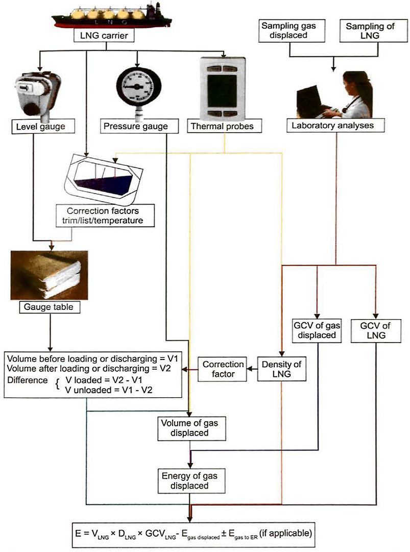
The energy value of the cargo transferred during loading or unloading is calculated using the formula:
where:
- E – is the energy transferred from the loading facilities to or from the LNG carrier and unloading facilities. The energy transferred is most frequently expressed in MMBTU.
- VLNG is the volume of LNG loaded or unloaded in m3;
- DLNG is the density of LNG loaded or unloaded in kg/m3
- GCVLNG is the gross calorific value of the LNG loaded or unloaded in MMBTU/kg.
The gross calorific value (GCV) of gas used in international LNG trading corresponds to the quantity of heat produced by complete combustion in air of a unit of volume or moss of the gas, at a constant standard absolute pressure and a constant standard condensation temperature of the water formed during the combustion. The unit of volume of gas is also considered at a standard temperature and pressure.
The standard pressure used in the calculation of the GCV is 1,01325 bar, although the standard reference temperature may be 0 °C, 15 °C, 15,56 °C (60 °F) or 25 °C.
Similarly, several standard reference temperatures and pressures may be used for the unit volume of gas.
The standard temperatures and pressures used in the calculation of the GCV are normally specified in the commercial contract between buyer and seller.
Egas displaced is the net energy of the displaced gas, also in MMBTU, which is either:
- the gas sent back onshore by the LNG carrier when loading (ie the volume of gas in cargo tanks displaced by some volume of loaded LNG);
- the gas received by the LNG carrier in its cargo tanks when unloading/replacing the volume of discharged LNG.
Egas to ER, where applicable, the energy of the gas consumed in the LNG carrier’s engine room during the time between opening and closing custody transfer surveys, ie used by the vessel at the port, which is either:
- added to the total energy transferred for on LNG loading transfer;
- subtracted from the total energy transferred in LNG unloading transfer.
Egas to ER may be the actual quantity of gas consumed as calculated from fuel gas flow meters onboard the LNG carrier, or a fixed quantity or volume contractually agreed between buyer and seller.
To complete the energy transfer calculation, the following measurements are required:
- the LNG volume in the ship’s tanks;
- the density of the LNG;
- the GCV of the LNG;
- the energy of the gas displaced during the transfer of the LNG;
- the energy of any gas consumed in the LNG carrier’s engine room during the loading or unloading operation.
LNG volume in the ship’s tanks
The LNG volume in the ship’s tanks is determined using level gauges of certified accuracy and calibration tables certified by an approved surveyor.
A secondary gauging system is provided in each cargo tank as a backup in the event of a failure or fault in the primary system.
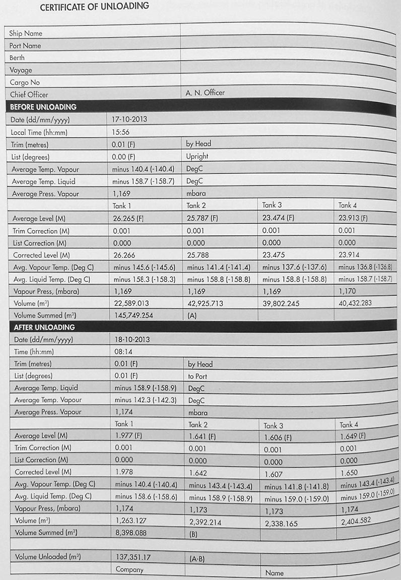
Most LNG carriers are equipped with an automatic gauging system, referred to as the custody transfer measurement system (CTMS). The CTMS generates the following reports:
- opening custody transfer (OCT), detailing the cargo tank levels, volumes temperatures and pressures immediately prior to cargo transfer, either loading or unloading;
- closing custody transfer (CCT), detailing the cargo tank levels, volumes temperatures and pressures immediately following completion of loading/unloading;
- loading/unloading certificate, that details the quantity of LNG liquid transferred. This is the difference in LNG quantity onboard between the OCT and CCT measurements.
The CTMS system converts the measured LNG levels in each cargo tank into the corresponding LNG volume in the cargo tank using the certified tank calibration tables incorporated in the system software and by applying correction factors for trim, list and temperature as appropriate. The CTMS documents are, typically, witnessed by the ship’s Master and a representative of the buyer or seller, as appropriate.
Density and gross calorific value of the LNG
LNG is a composite gas, principally methane but with varying smaller proportions of nitrogen, ethane, propane and butane. The composition of these components, and resultant density and gross heating value of the LNG, will change during the course of a loaded or ballast voyage if BOG is used as fuel.
The density (DLNG) and the gross calorific value (GCVLNG) of the LNG transferred is determined on the basis of the average composition of the LNG. The average composition is determined by either:
- continuous or discontinuous sampling of LNG in the LNG transfer line(s) between the ship and the terminal. The mole fractions of the constituent gases in the composite sample are then determined using gas chromatographic analysis;
- online, time weighted gas chromatographic analysis, using a sample probe located in the LNG transfer line(s), to determine the mole fractions of the constituent gases.
In either case the compositional analysis is made of the LNG vapour, not the liquid.
An LNG liquid sample is passed through a vaporiser to provide the vapour sample for analysis. The sampling is normally conducted during the period of steady state transfer and excludes periods at the beginning and end of the transfer, when the transfer rate is being increased or decreased.
International standards exist for the methods and techniques used for LNG custody transfer, such as ISO 8943 “Refrigerated light hydrocarbon fluids – Sampling of liquefied natural gas – Continuous and intermittent methods” (Reference 2.71), ISO 6974-5 for gas chromatography (Reference 2.72) and either ISO 6976 (Reference 2.73) or GPA 2261-00 (Reference 2.74) for calculation of the GCV of gas.
The actual standards used for calculating the energy transferred in a particular transaction are contractually agreed between buyer and seller.
It will be interesting: Liquefied Petroleum Gas Reliquefaction Plant and Boil-Off Control
Industry practice regarding LNG custody transfer can be found in the International Group of Liquefied Gas Importers (GIIGNL) publication, “LNG Custody Transfer Handbook” (Reference 2.22).
In certain operations, such as LNG ship to ship transfer, it may not be possible to obtain a representative compositional sample for analysis. In these circumstances the buyer and the seller may agree to mathematically “weather” the load port composition, using a known bod-off quantity and differential pressures of the mole percentage of the LNG components, to determine the composition of the LNG at the time of the ship to ship transfer.
Energy of the gas displaced during the transfer of LNG and of any gas consumed in the LNG carrier’s engine room
The vapour transferred between the LNG carrier and the terminal during loading and unloading operations is BOG from ship or shore tanks and it will have a different composition to the LNG from which it is derived. The BOG will typically contain a larger proportion of the lighter components than the liquid LNG.
The same will apply to any boil-off cargo vapour consumed in the ship’s engine room between OCT and CCT.
In most cases it is not possible to accurately calculate the composition of either Egas displaced or Egas to ER· The GCV of pure methane is typically assumed when calculating the energy values of these elements of the energy transfer calculation.
The volume and density of LNG transferred is calculated using a standard temperature and pressure and, therefore, the actual temperature and pressure of the LNG quantity transferred will be corrected to the contractually agreed standard.
Similarly, the actual vapour pressure and temperature of Egas displaced or Egas to ER must also be corrected to agreed standard values.
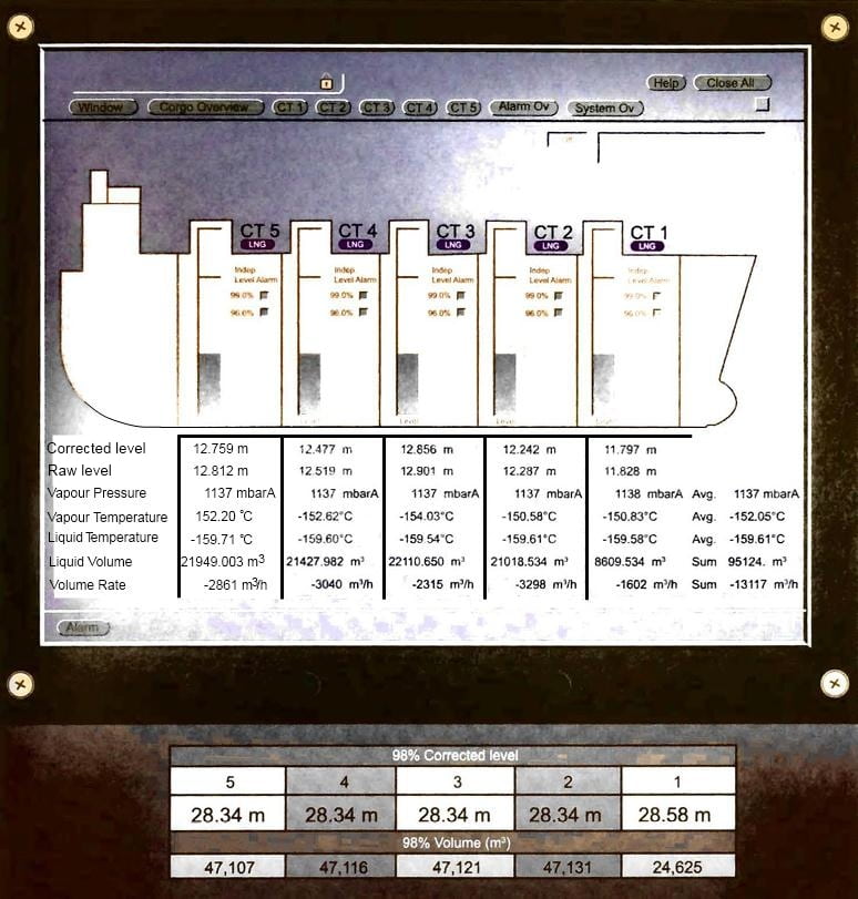
A range of temperature sensors, typically five, located at different heights throughout the liquid and vapour column are used to provide average liquid and vapour temperatures in each tank. The temperatures are averaged across the cargo tanks to provide the average liquid and vapour temperatures used in calculating the energy value of the transferred LNG.
Pressure gauges indicating absolute pressure in mbar are located in each cargo tank. A mathematical average of the pressures in each tank is used to determine vapour pressure when calculating the energy value of Egas displaced·
Example of contractual requirements for the measurement of the energy transferred at an LNG unloading terminal
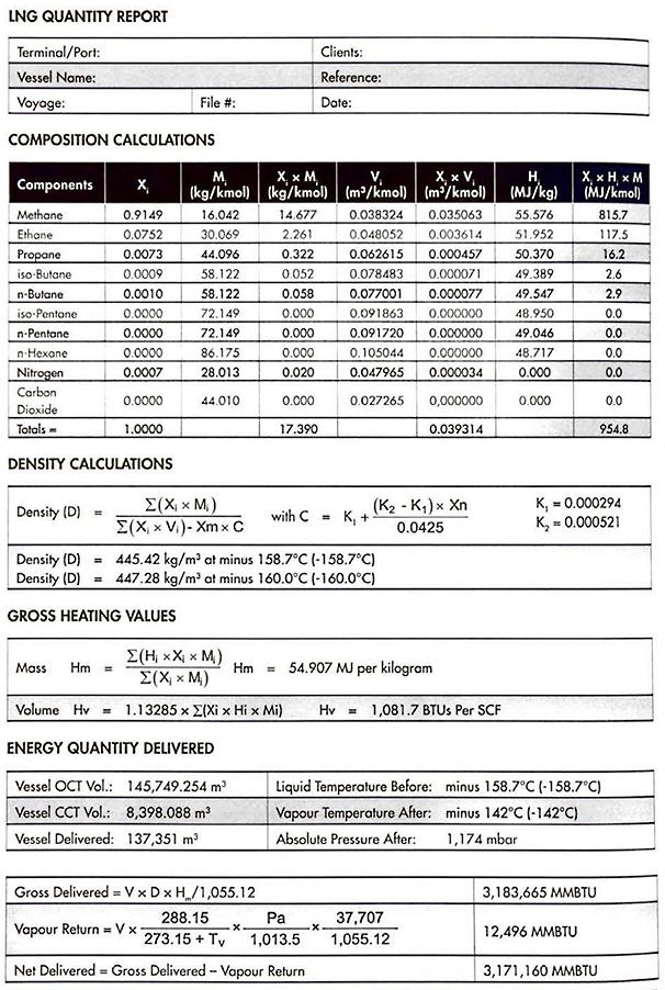
The calculation procedures contained in this point follow IP251/76, found in the Institute of Petroleum Measurement Manual, Part XII, Section 1 of the “IP Petroleum Measurement Manual HM 21” (Reference 2.75), while using the physical constants for Hi and Mi, derived from GPA Standard 2145-09 (Reference 2.76).
Th following notations or used:
- d – density of liquid cargo unloaded at the prevailing composition and temperature Ti, in kg/m3;
- Hi – gross heating value (moss based) of component ‘i‘ in MJ/kg;
- Hm – gross heating value (moss based) of the liquid cargo unloaded in MJ/kg;
- Hv – gross heating value (volume based) of the LNG delivered in BTU/standard cubic foot (SCF);
- K1 – volume correction in m3/kmol at temperature T1;
- K1 – volume correction in m3/kmol at temperature Tv.
- Mi – molecular mass of component ‘i‘ kg/kmol;
- P – overage absolute pressure of vapour in on LNG ship immediately after unloading in mbar;
- T1 – overage temperature of liquid cargo in on LNG ship immediately before unloading in degree Celsius;
- Tv – overage temperature of the vapour in on LNG ship immediately after unloading, in degree Celsius;
- V – volume of liquid cargo unloaded in m3;
- Vi – molar volume of component ‘i‘ in m3/kmol at T1;
- Xi – molar fraction of component ‘i‘ of samples taken from the receiving lines, determined by gas chromatographic analysis;
- Xm – the value of Xi for methane;
- Xn – the value of Xi for nitrogen.
BTU calculation of the quantity of LNG
The number of MMBTU contained in the quantity of LNG delivered, “Q“, is calculated using the following formula:
In which:
37,707 represents the gross heating value of the vapour returned to the LNG carrier, assumed as 100 % methane, in MJ/m3 at 15 °C and 1013,25 mbar, according to GPA Standard 2145-09 (Reference 2.76).
Calculation of gross heating value (volume based)
The calculation of the gross heating value (volume based) in BTU/SCF is derived from the same composition analysis as is used for the purpose of calculating the gross heating value (mass based) Hm. The following formula applies:
Where:
- 1,13285 – is the conversion factor of MJ/kmol into BTU/SCF.
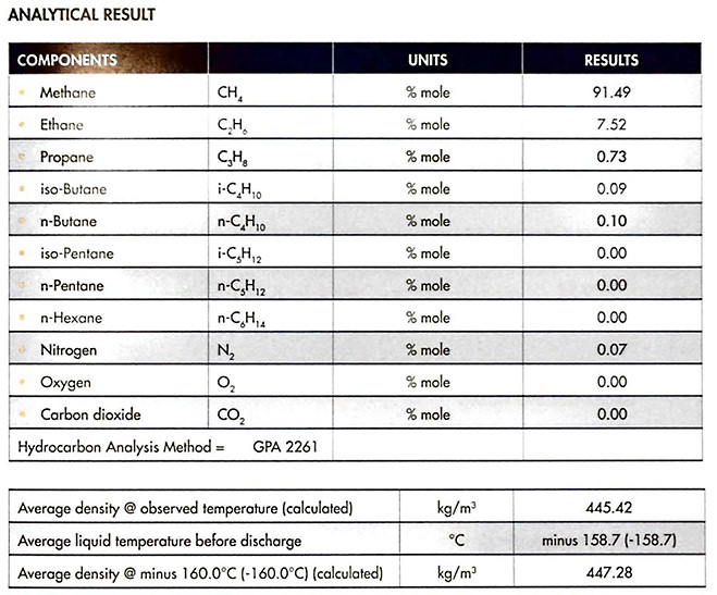
Figures 14, 15 and 16 are examples of the documentation for an unloaded cargo and the output in MMBTU, following the calculation methods outlined above.
CERTIFICATE OF ANALYSIS
| Terminal/Port: | Clients: |
| Vessel Name: | Reference: |
| Voyage: | Date: |
SAMPLING
The following are the composite results of testing multiple samples of <LNG drawn by terminal personnel from the shore line utilising the in-line GC owned and operated by the terminal and are submitted results.
Cargo Documentation
The transport of liquefied gas is subject to similar commercial documentation as that used for oil cargoes.
Certificate of Quantity
This is issued by the loading terminal as, or on behalf of, the shipper and is a declaration of the quantities of cargo loaded. The accuracy of the declaration may be verified by an independent surveyor.
Certificate of Quality
This is issued by the loading terminal as, or on behalf of, the shipper or by an independent surveyor appointed by the same. It is a declaration of the product’s specification and quality in terms of physical characteristics (such as vapour pressure and density) and constituent components.
Certificate of Origin
This is issued by the producer or shipper and is usually subject to confirmation by the Customs authorities in the exporting country. It declares the country in which the cargo was produced and may be relied upon by Customs authorities in the importing country for the assessment of any import taxes, levies or grants.
Time Sheet and Statement of Facts
The time sheet is a record of events occurring during a ship’s port call. It is usually prepared by, or on behalf of, the terminal and is the basis upon which a draft Statement of Facts is then prepared, before being presented to the Master for agreement (assuming the record of events is accepted as accurate).
The events included are all those that are relevant to the assessment of the ship’s utilisation during this period, in particular the progress of cargo operations. It is for this reason that it is usually relied upon in the assessment of demurrage or other loss of time based claims.
Cargo Manifest
This is a list of all cargoes carried onboard the ship. It is prepared at the loading port by, or on behalf of, the shipowner.
Its main purpose is to provide readily available data of all the cargoes carried onboard. This is usually for the benefit of the authorities (eg Customs) at the discharge port.
Certificate of Tank Fitness
This is usually issued by a cargo surveyor, upon inspection by a chemist. These are issued where the condition of the tank (eg cleanliness) is required to be established prior to loading.
Certificate of Inhibitor Addition
This is issued by, or on behalf of, the loading terminal or the producer of the cargo. An example of such a document is shown in Figure 14.
Mate’s Receipt and Bill of Lading (B/L)
Traditionally, a Mate’s Receipt was issued to the shipper by the Chief Officer of the ship. In preparing the description of the cargo upon the receipt, the Certificates of Quantity, Quality and Origin would be considered, along with due consideration of the ship’s own figures or observations.
Upon being presented with the Mate’s Receipt by the shipper, the carrier (the party that is contractually required to perform the carriage of the cargo) would then prepare and issue as B/L to the shipper.
The B/L has three distinct functions. It serves as:
- A receipt for the cargo described.
- A document of title in the hands of a transferee (eg a subsequent buyer of the cargo).
- Evidence of the contract of carriage.
As a receipt, it allows the party entitled to receive the cargo to rely upon its description of the car as being accurate and to look to hold the carrier responsible should there be a difference between the cargo received and that described (to the extent that any difference is not excused by the terms of the contract of carriage, ie the warranted boil-off rates (BORs) in the context of an LNG cargo).

