LNG characteristics play a crucial role in its application as a fuel source. The unique properties of liquefied natural gas, such as its low emissions and high energy density, make it an attractive alternative to traditional fuels.
- Scope, Applicability & Definitions
- Scope
- Applicability
- Objectives
- LNG as Fuel
- LNG as Fuel – General Aspects
- LNG Characteristics
- LNG Value Chain
- LNG Bunkering
- LNG Bunkering Modes
- LNG Bunkering Equipment, Ships and Infrastructure
- General Good Practice by Port Authorities & Administrations
- LNG as Fuel for Ports
- LNG Supply Chain
- LNG Bunkering operation – General aspects
- LNG Bunkering equipment
Additionally, understanding these characteristics is essential for optimizing the LNG value chain and ensuring efficient bunkering operations. As the demand for cleaner energy solutions grows, LNG‘s advantages become increasingly significant in various industries. Overall, the effective utilization of LNG hinges on a comprehensive understanding of its characteristics and the infrastructure required for its deployment.
Scope, Applicability & Definitions
This Guidance sets best practice control measures for LNG bunkering, and small scale LNG storage, relevant to Port Authorities-Administrations in their role on permitting, evaluating, approving, certifying, controlling, overviewing, documenting and providing/coordinating response in case of emergency.
Scope
The scope of this Guidance is limited to LNG bunkering Elements related to LNG as cargo, LNG terminals or other LNG wider value chain are excluded from the scope of this Guidance.x, covering the following elements Scope for the EMSA Guidance based on a gap analysis of existing references, in the context of the EU LNG Study, LOT1,x:
Regulations:
- High level instrument at EU and international levels, relevant for LNG bunkering.
- Standards.
- Guidelines.
- Industry best practice.
- Port Regulations.
Permitting:
- Spatial planning.
- Approval of bunker locations.
- Definition of simplified.
- Overall responsibility for the good governance and framework for LNG bunker operations in the port.
Emergency:
- Approval of safety and emergency response plans.
- Emergency Preparedness & Response Plan.
- Shore side contingency plans, emergency response systems.
- Definition of emergency procedures for the different types of LNG Bunkering.
- Best practice in response to LNG Hazards.
Certification:
- Accreditation of the Bunker Facility Operator (BFO).
- Qualification of the Person in Charge.
- Applicability of an accreditation scheme for LNG bunker operators in the ports under their authority.
- Certification of LNG bunker barges, non-IGC Code bunker vessels.
Operations:
- Control Zones.
- Safety Distance approval.
- Simultaneous operations (SIMOPS).
- Mooring of the receiving ship and bunker facility.
- Check-lists.
- Operational Envelopes (weather conditions, sea state, wind speed and visibility).
- General Procedures for Port Authorities.
Risk & Safety:
- LNG Bunkering Risk Assessment.
- Definition of Risk Acceptance Criteria.
- Evaluation of Risk Assessment reports – Best practice for the evaluation of Risk Assessment report.
Quality Management:
- Several elements considered relevant to ensure the quality of the LNG bunkering process, from a PAA perspective.
- Check-lists updated to include relevant indications for PAAs.
- Incident Reporting.
- Port Bye laws. Best practice in setting up port specific requirements.
Training:
- Training Matrix with identification of multiple training requirements in the Bunkering Interface.
- Competencies, Qualifications and Training for LNG Bunkering.
- Qualification for the PIC.
- Training Certification.
Applicability
The EMSA Guidance applies to Port Authorities/Administrations (PAAs) when involved in LNG Bunkering within their areas of port jurisdiction, either during the exploratory and planning phases or, at later stages of development, already in the context of actual LNG Bunkering operations.
The EMSA Guidance is applicable in a complimentary way to existing Standards, Guidelines and Industry Best Practice instruments, aiming to provide best practice recommendations to PAAs wherever their action is relevant, in control, evaluation, or even in guidance on the several different aspects of LNG bunkering.
The EMSA Guidance is applicable to the control of LNG The Role of LNG Bunkering Infrastructurebunkering operations by PAA in EU Core Ports, wherever EU law is applicable. It is applicable for:
- Different LNG Bunkering methods, Fuelling with LNG at berth and Shore-side LNG electricity production.
- Different ship types and
- Different locations (in port, off shore and terminal) worldwide.

Notes:
1 Regulatory frame applicable to LNG bunker barges/boats/ships will depend on their area of operation. If below 500GT an not engaged in international voyages, in principle, IGC Code does not apply (unless enforce by national legislation). ADN agreement applies, to all LNG barges/boats/ships of contracting parties, engaged in the inland waterway transport of LNG.
2 Port Administration is, in the context of the EMSA Guidance, a holder of administrative responsobility; possibly with partial delegated authority (this can typically be the case of a private Port of a landlord Port(mostly responsible for leasing the land). Different local, regional or national context should her be taken into account.
3 The Guidelines from ISO, IACS and SGMF offer guidance and establish requirements cover Functional Requirements for LNG bunkering equipment, responsibilities of RS and BFO, Risk Assessment principles, amongst other aspects relevant for interaction (A) above.
4 Recieving Ship is assumed to be either an IGF Code vessel (if constructed, or converted to LNG fuel, after 1 January 2017). Before that date the IMO Interim Guidelines apply ( Res. IMO MSC.285(86) Interim guidelines on safety for natural gas-fueled engine installations on ships (2009)).
Objectives
The objectives defined for the EMSA Guidance on LNG Bunkering are to assist Port Authorities/Administrations with:
- The necessary elements to develop a harmonized procedure for the evaluation, control and through-life assessment of LNG bunkering projects.
- Definition of a unified set of first principles for permitting and approval, including a common risk assessment evaluation approach and common suggested risk acceptance criteria for the bunkering of gas as fuel in the respective.
- Implement harmonized bunkering procedures in EU ports to reduce the potential confusion caused by having to comply with different rules and regulations in different ports.
- Clear suggested definition for the responsibilities of the different involved parties including landside and waterside authorities regarding the bunkering of LNG, both in in case of normal operation and in case of malfunction or emergency.
- Definition of a procedure to allow evaluation, control and authorization of SIMOPS with LNG bunkering.
- Proposal for a harmonized approach to the approval of Control Zones in different bunkering scenarios, through the implementation of a concept of «meaningful protection». In addition to a deterministic or probabilistic approach, it is suggested to include a context-based approach where the determination of Control Zones is driven mostly by the presence of elements meriting protection in the vicinity of the LNG bunkering location.
LNG as Fuel
The present section is focused on the aspects that make today LNG as fuel a viable technical option for ships, from the very own fuel characteristics, to the value chain, different bunkering options and concepts. LNG characteristics are presented with a focus on its physical properties. The LNG value chain is then broadly addressed with a view to identify the main general transformation and distribution links from LNG production to LNG transfer into an LNG fuelled ship.
In addition, LNG Bunkering is defined, with different options presented as to how LNG fuel chain can be designed within a Port Area. How the LNG/NG arrives to the Port, how it is stored or processed, distributed, and finally how it is transferred/bunkered to an LNG Fuelled Ship.
Along with the informative content of this section some recommendations are included, in section 2.8*, on how PAAs should integrate basic LNG bunkering options and elements contributing to the overall design of LNG bunkering solutions affecting the Port area.
LNG as Fuel – General Aspects
LNG as fuel for shipping, as an emerging market segment, is already shaping new ship design, technical options and operations. Mostly driven by first-front demand and higher risk-taking funding/investment initiative, LNG bunkering has incorporated increasingly complex and customized solutions. This is the case for ship design, with more ambitious LNG fuel systems, capacity and technology wise, but also for operations where the need to have Simultaneous Operations, along with LNG bunkering, is one of the essential elements for the viability of LNG fuel option for some types of ships (e. g. containerships or RO-PAX ferries).
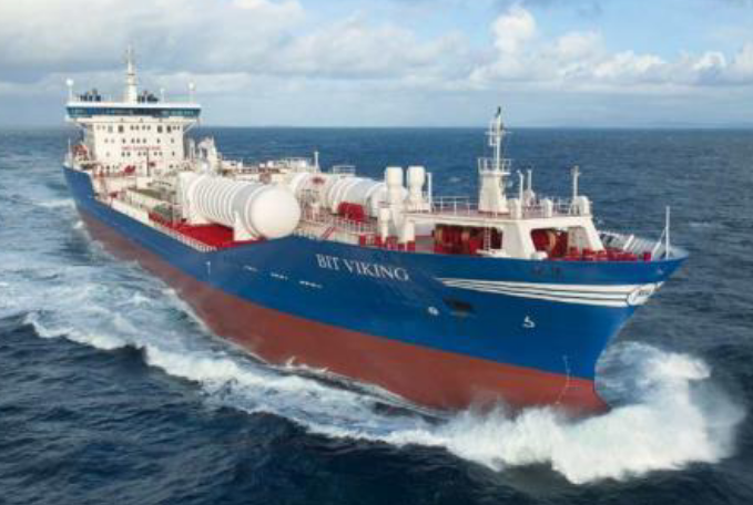
power. The conversion involved installation of new
dual fuel engines and LNG fuel system
The vessel is outfitted with an LNG fuel system comprising two LNG storage tanks with combined storage capacity of 1 000 m3. The storage tanks are located on the vessel’s deck. This also allows the bunkering of LNG at a rate of 430 m3 an hour.
The market has developed recently, even in the verge of a particular context driven by increasingly lower oil fuel prices. More LNG fuelled projects are developing and, in parallel, LNG bunkering options being characterized by an increasing higher-capacity portfolio of solutions.
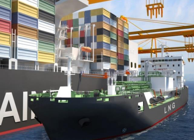
This specialized ship will have a capacity of 6 500 m3 and will be capable of fuelling 1 000 m3 of LNG per hour. As the market for LNG as Fuel increases in demand and LNG fuelled ships grow in LNG fuel capacity, the demand for LNG bunker barges will also naturally increase, with much higher capacities and available bunker rates when compared to LNG Trucks.
operation
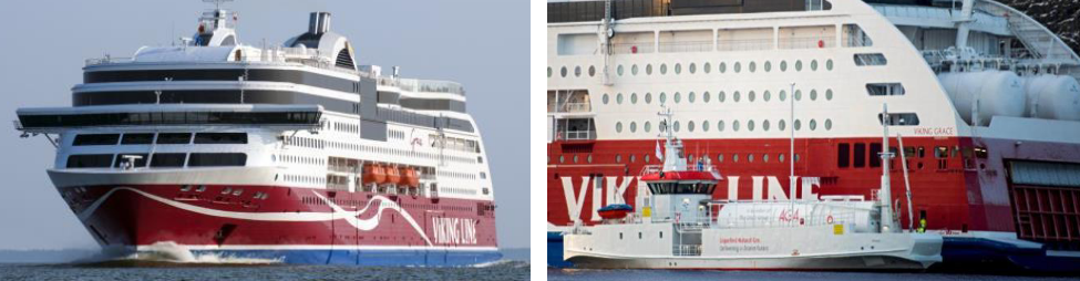
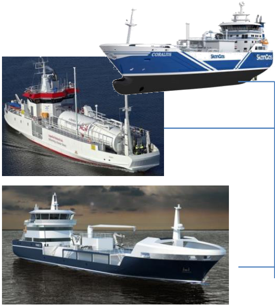
To note the LNG fuel tanks on the stern of the ship. The binomial «Receiving-Bunkering ships» is here seen as a clear indication of an LNG bunkering market in early stage of development. In the presented case the Seagas bunker vessel is dedicated to LNG supply to the Viking Grace. With a very significant number of successful operations conducted, the presented case is the example of a customized LNG bunkering solution has resulted in an exemplar safety case.
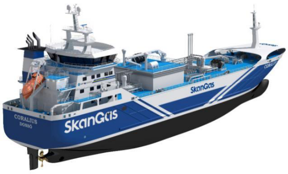
Bunker vessel with a cargo capacity of 5 800 m3 and is 99,6 meters long. She holds a Finnish/Swedish Ice Class 1A and is classed «LNG gas carrier IGC type 2G -165 °C, 500 kg/m3» Larger volumes of LNG are transferred at high rates with Coralius representing a new paradigm in flexibility for higher and diversified LNG bunkering demands.
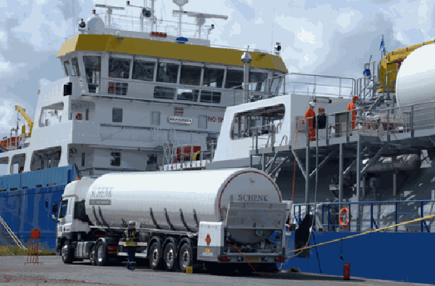
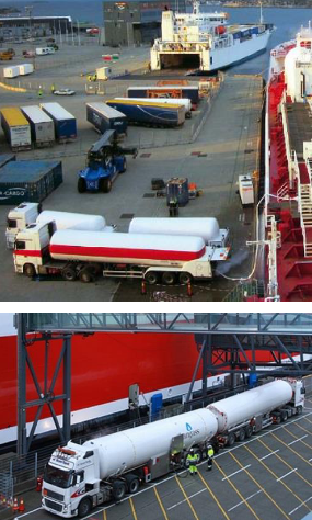
By far the most common method used today, representing an option that has allowed flexible operations and experience to build up. Notwithstanding adequate for limited LNG quantities LNG trailer trucks are typically limited to around 25 ton of LNG (around 50 m3x truck-to-ship LNG bunkering is unable to respond to higher demands in capacity or LNG transfer rates. As ships become more demanding for higher LNG volumes the transition to LNG bunker vessels or fixed LNG bunkering facilities will naturally take place.
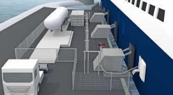
Variations of typical LNG truck-to-ship bunkering have also been developed, remarkably on what is called in the present guidance of LNG «feeding», as presented in these two images, one artistic impression and another one, on the right, of actual operation.
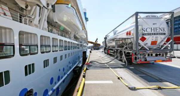
With LNG feeding the ship, otherwise with no LNG storage capacity on board, receives LNG directly from a truck trailer to consumption onboard. This allows the ships environmental profile at berth to be significantly improved, consuming cleaner burning natural gas, instead of oil fuels in port generators.
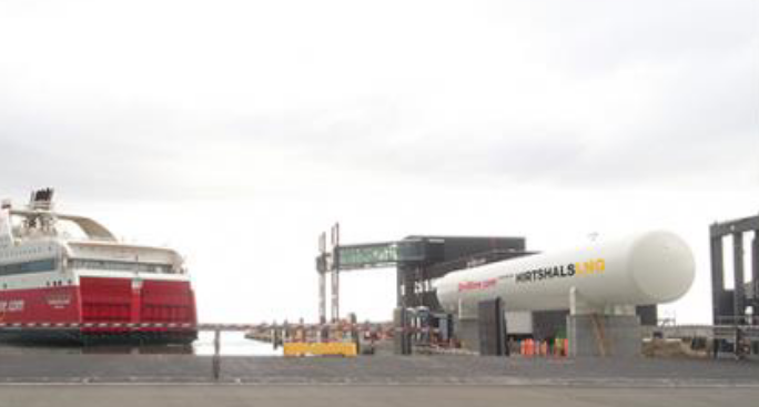
LNG storage tank
Having presented mobile LNG bunkering facilities, in Fig. 10, above, a fixed LNG bunkering location is shown, with type-C LNG tank.EU TEN-T co-financed pilot fixed LNG bunkering installation of 200 tonnes/445 m3 tank capacity Max Flow rate delivery of 200 m3/hour.
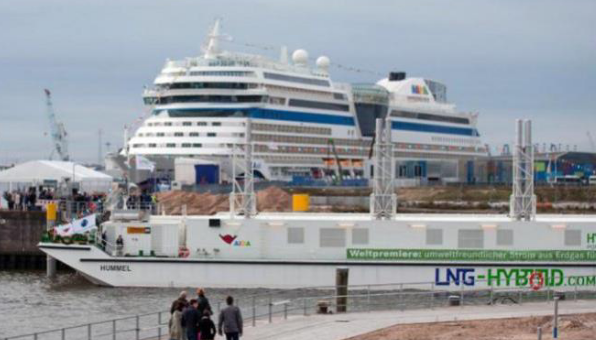
Even though not an LNG bunkering typical scenario, LNG fuelled electricity supply is also included in the context of this document. It involves typically mobile units such as the one presented – power barge supplying electricity from LNG (Liquefied Natural Gas) as Fuelgas dual-fuel generators onboard, directly to the cruise vessel alongside in a close position.
Even though outside the scope of this document, the LNG bunkering market development is an important aspect that PAAs will have to consider. On one hand the number of ships that can be expected in a near future to be built, converted, or prepared for LNG as fuel.
Currently it is possible to obtain information on the prospects of LNG as fuel from different sources, not only on the number of ships built and operating on LNG but also on the infrastructure development. These two aspects are often regarded as interdependent and should, from a practical point of view also be considered as relevant information elements to PAAs evaluating, promoting or assessing a prospective LNG bunkering facility project.
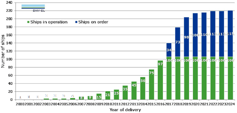
The number of LNG fuelled ships, in operation and on order is presented in fig. 12.
Whilst fig. 13 shows the areas of operation, based on AIS information, where LNG fuelled ships operate today.
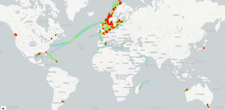
information – update May 2017
It does not go unnoticed from fig. 12 that LNG-fuelled ships in operation and on order have reached a maximum growing rate between 2014 and 2016, having recently stabilized mainly due to a reduction in oil fuel price driving shipowners to either delay the decision to convert to LNG or to choose another technical option for compliance with emission regulations. The future is however uncertain and, for the purpose of the present document, the important aspect to retain is that LNG as fuel will be an increasingly generalized option adopted in shipping. This reflects in the diversification of the LNG as an off-grid fuel solution for maritime transport.
An important aspect for the development of LNG as fuel is the infrastructure. The small-scale developments are therefore important in the definition of LNG bunkering facility projects and, consequently, for the sizing and specification of the adequate LNG bunkering solutions within a port.
An adequate overview of the LNG small-scale infrastructure is therefore important to PAAs. The GIE small-scale LNG map provides the LNG industry and interested parties with an overview of the available, under construction and planned small-scale LNG infrastructure and services in Europe.

The GLE small-scale LNG map provides the following information:
LNG import terminals offering new LNG services:
- Reloading: Transfer of LNG from the LNG reservoirs of the terminal into a vessel.
- Transhipment: Direct transfer of LNG from one vessel into another.
- Loading of bunker ships: LNG is loaded on bunkering ships which supply to LNG-fuelled ships or LNG bunkering facilities for vessels.
- Truck loading: LNG is loaded on tank trucks which transport LNG in smaller quantities.
- Rail loading: LNG is loaded on rail tanks which transport LNG in smaller quantities.
LNG small-scale liquefaction plants:
- LNG is produced in small scale liquefaction plants to respond to peak shaving demand or make available natural gas to regions where it is not economically or technically feasible to build new pipelines.
LNG bunkering facilities for vessels:
- This stationary facility allows ships to bunker LNG to be used as fuel for the vessel.
LNG bunker ship:
- This ship supplies LNG directly to LNG-fuelled ships or to LNG bunkering facilities for vessels.
LNG refuelling stations for trucks:
- This facility allows trucks to fill LNG to be used as fuel.
LNG satellite storage:
- They enable to store LNG in small quantities in areas where there is no high pressure pipeline. LNG is delivered mainly by trucks (but also by small LNG ships) to these satellite plants where it is then stored and regasified into the natural gas distribution networks or used by an end user.
LNG Characteristics
LNG (liquefied natural gas) is the name given to natural gas that has been converted to liquid form by being cooled to a very low temperature. To attain a liquid phase, the temperature must be lower than the critical temperature (-82 °C in the case of methane). LNG is typically stored at near-atmospheric pressure at close to its atmospheric boiling point (-160 °C). In liquid form, natural gas occupies 600 times less volume that in a gaseous state, making it easier to transport over long distances and enabling a large storage capacity to be achieved in a relatively small space.
The main characteristics and hazardous properties of liquefied and gaseous natural gas are summarised in table 1 and discussed in the paragraphs below.
| Table 1. LNG Physicochemical properties | ||
|---|---|---|
| Properties | Notes | Value |
| Physical State | Cryogenic liquid under special PVT conditions | cryogenic liquid |
| Boiling Temperature at 1 bar [°C] | This is the temperature at which the vapour pressure of the material equals ambient pressure. Pure substances boil at specified pressure at a defined temperature. This temperature stays constant under continued addition of heat until all material is vaporised. Mixtures usually have a boiling range. | -161 |
| Density at 15 °C [kg/m3] | Density at (-160 °C,1 bar) | 448 |
| Lower Heating Value [MJ/kg] At (-162 °C and 1 bar) | LHV gives a measure of the energy density by mass of the fuel. This parameter impacts on storage space in conjunction with density but can also provide an indication of the amount of heat released in a fire in conjunction with heat of evaporation. LNG has an LHV of 50 MJ/kg which 15 to 20 % higher than that of HFO and MGO. Thus approximately the same LNG fuel by weight must be bunkered to obtain the same energy on board. With respect to fire, the higher LHV of LNG implies that more heat will be released per mass of fuel as compared to MGO and HFO. | 50 |
| Vapour Density air=1 | This parameter is interesting in order to gauge whether a vapour is likely to sink and accumulate in low areas or rise and accumulate in high areas. Methanol vapour density is very close to that of air, so it is near to neutral in buoyancy. The vapour density of anhydrous ethanol is 1,6, which is heavier than air. As LNG is at ambient conditions gaseous, but stored at less than -160 °C the vapour density discussion is more complex. Should a spillage occur the cold vapours may initially be heavier than air until they have warmed up sufficiently? Liquid density of LNG at -160 °C and 1 bar is 448 kg/m3. At 1 bar abs and -162 °C pure methane is in subcooled condition. Gas density of pure methane at 0°C and 1 bar (normal conditions) is 0,71 kg/m3 (superheated condition). | 0,55 |
| Flash Point (TCC) [°C | Flash point is the lowest temperature at which a liquid gives off enough vapour at the surface to form an ignitable mixture in air. Flash point is one of the valid indicators of the fire hazard posed by the fuel. The flashpoint of LNG at -175 °C is much lower than any oil fuel, and even much lower than other low flashpoint fuels such as methanol (12 ºC) or even ethanol (17 ºC). The challenge is therefore not to avoid formation of vapour due to heating of LNG but rather to manage, contain and, ultimately, use the generated vapour. | -175 |
| Auto Ignition Temperature [°C] | The auto ignition temperature is defined as «the temperature at which a material self-ignites without any obvious sources of ignition, such as a spark or flame». It is a function of the concentration of the vapour, the material in contact and the size of the containment. | 540 |
| Flammability Limits [by % Vol of Mixture] | Flammability limits give the range between the lowest and highest concentrations of vapour in air that will burn or explode [v]. Methanol’s flammability limits are wider than those of ethanol, LNG, and MGO. | 4,5-16,5 |
| Min. ignition energy at 25 °C [mJ] | This is the lowest amount of energy required for ignition. This parameter is highly variable and dependent on temperature, amount of fuel and the type of fuel. Methanol, ethanol, and LNG all have minimum ignition energy below 1 mJ at 25 °C, whereas for MGO it is 20 mJ. | 0,29 |
| Flame temperature (ºC) | Temperature attained to lean burning LNG pool fire | 1 875 |
Composition
LNG is typically a mixture of hydrocarbons consisting mainly of methane with smaller fractions of inter alia ethane, propane and nitrogen. The LNG imported to Europe typically consists of methane (90 weight percent) and ethane (10 weight percent). Components such as water vapour, carbon dioxide and heavier hydrocarbons have already been removed from the LNG.
When the LNG is vaporised, it is methane that is first released as vapour. This is due the difference in atmospheric boiling point between methane and ethane. More precisely, the vapour will consist almost entirely of pure methane as long as no more than around 70 % of the liquid has been vaporised.
Physicochemical Properties
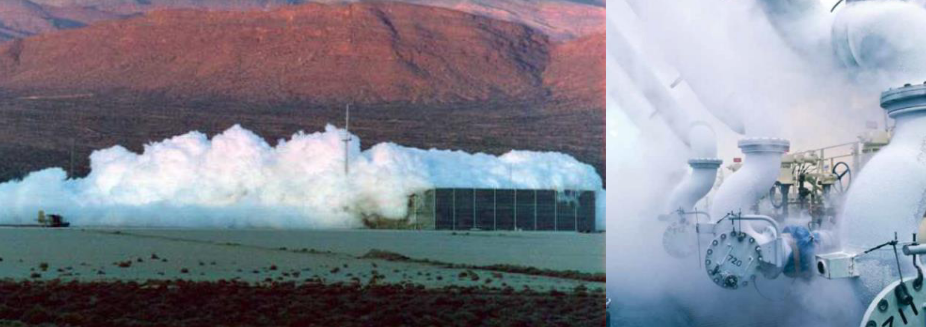
Methane is a colourless and almost odourless gas. When LNG is released into the environment, cold vapours are formed that result in condensation of the water vapour present in the air. This phenomenon means that LNG vapour is visible at low temperature due to the mist created.
The cold vapours formed by the vaporising of LNG are initially heavier than air and disperse close to the ground. As they mix with the ambient air, the cold LNG vapours gradually heat up and will behave neutrally at temperatures of around -110 °C, eventually becoming lighter than air under normal pressure and temperature conditions. At ambient temperature and pressure, natural gas has a density of around 0,72 kg/m3.
Understanding the dispersion behaviour of LNG clouds, following an accidental release is a determining factor to design adequate Control/Safety Zones and safeguard systems for LNG bunkering. Clouds are asphyxiating due to oxygen depletion and explosive interval will be present in the limiting boundaries of the cloud.
Condensation cloud formation around LNG piping, hoses, and manifolds is the result of water condensation surrounding cryogenic temperature elements of the LNG bunkering interface. The less insulated the bunkering lines are, and the more humid the surrounding atmosphere, the more condensate cloud formation and frost cap around piping will be generated.
Hazardous Properties
LNG vapour in air is flammable within specific concentration limits. As LNG vapour consists mainly of methane, the flammability limits of methane (4,5–16,5 vol. %) are generally used to estimate the size of the flammable clouds formed after an incidental release of LNG.
It should also be noted that free natural gas clouds, once ignited, burn at a relatively low speed, which means that only relatively small overpressures are likely to occur in an open environment (≤ 50 mbarg). Only if the flammable natural gas cloud formed is confined or is present in an installation with a high obstacle density may higher overpressures possibly occur in the surrounding area.
A pool fire or jet fire that occurs after an incidental release of LNG is characterised by a bright flame (little soot formation) and high radiation intensity (typically: 200–300 kW/m2). The effects of an LNG fire on nearby people or installations are therefore greater than those of fires that occur after an incidental release of conventional fuels such as petrol or diesel.
Finally, it should be noted that direct contact with LNG (as a cryogenic liquid) can result in serious freezing injuries. If LNG comes into contact with steel, the steel will embrittle due to the low temperature and a steel structure may fracture. Stainless steel retains its ductility at low temperatures and is therefore more resistant to contact with cryogenic liquids.
LNG Value Chain
From Natural Gas source to final consumers the LNG value chain can assume different shapes and be designed in different ways, depending on the needs for a variety of end-users. Fig. 16 below shows a very simplified representation of a generic value chain, distinguishing between two different types of consumers: LNG and NG consumers.
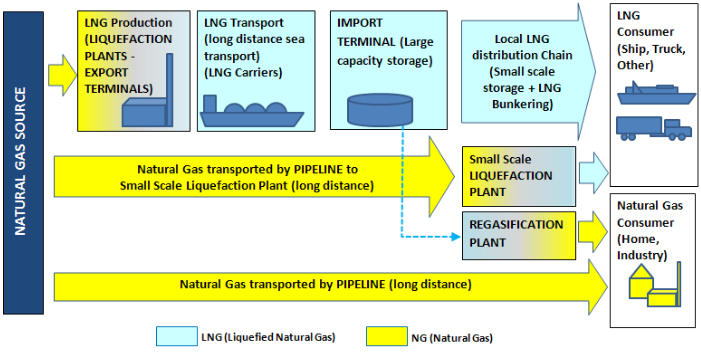
These typically represent the transport and domestic/industrial users, respectively. The chain is characterized by the liquefaction and re-gasification points where NG transforms into LNG and vice-versa. The need for LNG is associated with 2 (two) essential needs:
- the need to transport NG through long distances or
- the need to provide NG for mobile users.
Since LNG occupies 600 times less volume than NG it is also convenient for storage wherever limited space is available. This is obviously the case for ships, and other mobile units, but can also be the case for land-side developments, off-grid, potentially close to shore where LNG use may be convenient.
There are several aspects to be carefully considered when designing an LNG chain, but one main rule applies: The more interfaces, liquefaction plants, distribution links, the more likely it will be to have LNG accidental or operational releases. In liquefaction plants LNG compressors are likely to have small LNG leaks leading to undesired methane emissions. In addition to the potential environmental impact it is also important to have safety into consideration, remarkably where the more transitions in phase and interface operations will represent also a potentially higher risk of accidental releases.
Finally, it is important to note that a significant part of the LNG value chain can be contained within the boundaries of a Port and, especially if a multi-modal hub The tendency to have multi-modal hubs where LNG is supplied to different transport mode units will be potentiated by the TEN-T network, where EU core ports also represent relevant multi-modal nodes in the network. x is also included, it will very likely be seen the co-existence of different stakeholders in the port area. Port rules and local regulations should not only have this notion into account but also realize the different regulatory frameworks that may be relevant for different parts of the LNG chain. Fixed LNG bunkering facilities and mobile units may coexist, giving the exact expression to the versatility of LNG as fuel.
The LNG value chain, from an import grid or natural gas network distribution, can be further decomposed into different supply routes. Fig. 17 exemplifies a possible representation of different supply routes.

Different stages are considered which can be generically taken as the example from the figure:
- Supply.
- Transport.
- Local storage or production and
- Bunkering.
We are only taking LNG fuelled vessels as the consumers in the diagram represented. In reality, however, this would be a multi-consumer environment that would be able to access LNG/NG from any point in the LNG chain.
LNG Bunkering, as an end-service within the LNG Value Chain will dictate, through demand, the shape of the local storage/production, whether trucks suffice, on a regular or spot delivery for bunker, or even whether local storage needs to be considered. Demand in terms of capacity (in total or per operation) will have to be considered, in this sense, at a very early stage. A careful consideration to the LNG Value Chain end, will avoid undesired operational losses, inadequate solutions and, ultimately, safety.
Elements affecting the LNG Value Chain
The following elements are considered as determinant in the shape and requirements for an LNG Value Chain:
- Consumer characteristics (location(s), consumption profile, cost vs. feasibility).
- Gas availability requirement.
- Supply (location(s), suitability, cost).
- Receiving terminals (need for break-bulk, location, type, sizes, investment cost).
- Shipping (vessels available, charter rate, fuel consumption).
- Boil-off gas (BOG) handling.
- Distance for LNG distribution (will dictate the distribution/transport mode for LNG) – the longer the distance for LNG distribution the higher should be the investment in insulation and, potentially, also the need for intermediate storage, liquefaction and refrigeration.
- LNG truck-trail loading in points where LNG road-rail mobile units load LNG for break-bulk distribution.
- LNG transhipment (Transhipment – operation technically similar to simultaneous unloading and loading – can be used to divide a large cargo into smaller ones (break- bulking), or to optimise the LNG tanker fleet between the sellers and buyers of a cargo (ship swap). Transhipment may also be called «Ship-to-Ship» (STS), even if STS usually refers to offshore cargo transfer through flexible hoses between side-by-side vessels. Transhipment is not covered by this Guidance as it deals with LNG as cargo, even if it may represent the break-bulk of cargo into smaller feeder vessels.) from larger scale LNG carriers to medium-smaller LNG feeder vessels or even LNG bunker vessels or barges.
- How far apart are end users/consumers from LNG Import Terminal? This will dictate how smaller scale LNG bunkering will develop and how will distribution of LNG be done to avoid losses and to minimize the number of transformation points.
Scale of LNG developments and facilities
In the context of this Guidance the scale of an LNG development/facility is often mentioned, in particular with reference to «small scale» LNG facilities. In the absence of exact criteria that would help to determine a separation between small, medium and large scale LNG developments, this Guidance establishes, as an indicative reference the single criteria approach, using for classification the LNG storage capacity of a given LNG facility. The whole scope of this Guidance is contained in the Small scale interval, with LNG storage capacities involved, either in pressurized or atmospheric tanks well below 10 000 m3.
| Table 2. Scale of LNG developments and facilities (single criteria: storage capacity | ||
|---|---|---|
| LNG Scale | LNG Storage capacities typically involved | Operations |
| Large | > 100 000 m3 | Liquefaction plant: A large-scale LNG operation typically includes production trains with single capacities between 1 and 6 MTPA (million metric tonnes per annum), and they can include multiple trains. Large liquefaction sites are always located in coastal areas since the only practical method of large-scale transportation is using LNG carriers, with capacities ranging from approximately 120 000 m3 (54 000 tonnes) for older vessels to up to as much as 267 000 m3 (120 000 tonnes) for the largest Q-max vessels. Receiving terminal: Conventional receiving terminals (LNG hubs) in the large-scale LNG chain are also located by the coast so that LNG carriers can arrive and unload the cargo. Main hubs include LNG storage facilities, typically in the range of 120 000 m3 or larger, designed to receive at least the full capacity of the allocated LNG carrier. The LNG is regasified at the hub, and the main distribution channel for the consumers is normally a national, high-pressure, natural gas pipeline. |
| Medium | 10 000 to 100 000 m3 | A medium-size LNG logistics chain includes terminal up to 100 000 m3 in size, which are supplied by small-scale LNG carriers, starting from sizes of 1 000 m3 to up to around 40 000 m3. Here again, the vessel size and loading frequency play an important role in determining storage capacity. Medium-scale liquefaction is not so common today, due to the challenge with high, specific production costs. In any case, these will probably play a larger role in the future for decentralised solutions, to which extending the large-scale logistic chain would not be feasible. |
| Small | < 10 000 m3 | A small-scale LNG logistics chain is comprised of LNG distribution to local users. In practice, this means highway truck transportation or small sea-going vessel distribution to the end-user’s local LNG tanks, which can be from the smallest container sizes of 20 m3 to up to a set of pressurised steel tanks with total capacities of up to a few thousands of cubic metres. Small-scale liquefaction is becoming popular due to the liquefaction of biogas and other smaller pockets of stranded gas. Small-scale liquefaction can be modularised and, to some extent, standardised. The systems are similar to the re-liquefaction process used in large terminals to handle the BOG (boil-off gas). |
LNG Bunkering
Definition
Regulation 2017/352 provides the more general definition, used in the context of this Guidance. Adapting that definition for the case of LNG bunkering the following definition is provided:
Provision of liquefied natural gas (LNG), to be used as fuel, used for the propulsion of the LNG fuelled waterborne vessel as well as for general and specific energy provision on board of the waterborne vessel whilst at berth.
LNG Bunkering is in fact a particular type of operation where LNG fuel is transferred from a given distribution source to a LNG fuelled ship. It involves the participation of different stakeholders, from the ship-side, LNG supplier, ports, safety personnel, administrations and policy makers. In addition to the supply of the LNG fuel itself, also the operation of supplying LNG sourced energy to the waterborne vessel, whilst at berth, is included in the present Guidance document.
LNG Bunkering Supply Mode
One of the main challenges with LNG Bunkering is the interfaces created during LNG delivery moment. These challenges can be either of a regulatory or technical nature, but not only. In fact, on top of particular standards and technological needs for LNG as a marine fuel to be bunkered safely, it is important to acknowledge the relevance of harmonization. The creation of interface environments in LNG bunkering raises the concern about how different regulatory frames («land side» vs «ship side», «road» vs «port», «road» vs «ship-side», etc.). Ideally regulations and requirements should tend towards harmonization and non-conflicting regimes, but this is not always the case. On top of this the interface can also unveil potential training discrepancies, equipment mismatches and other factors that can, ultimately, influence Safety and affect the Environment with unnecessary methane emissions. The minimization of risk to life and property, and the mitigation of gas release are the fundamental drivers to make the LNG chain inside the port area as lean and simple as technically possible.
From a PAA perspective in the definition of an LNG Bunkering concept the main elements that are considered for the present questionnaire are:
- How the LNG arrives to the port are;
- Whether it is intermediately stored within the port and
- How is the LNG delivered to the receiving vessel?
Different options are possible by the combination of replies to these questions. Table 3, below, includes a combination of different supply elements.
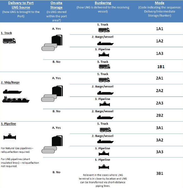
Many different combinations are possible. With these different combinations there are different regulatory instruments; at national, regional or international level which also concur (these are explored in Section 4*). The identification of potential conflicting requirements will also be relevant for the outlining of guidelines that may be able to resolve them, clarifying, streamlining and identifying possibly adjusted procedures.
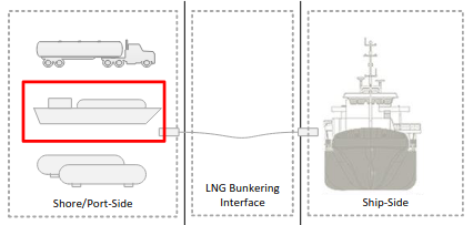
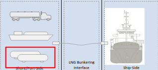
Also featured in the present Guidance the Special Modes presented in table 4 where, in fact, no transfer of fuel occurs in the interface (in S4 the transfer is of a containerized unit and in S5 or S6 the transfer is not of the LNG fuel but of LNG-sourced electricity).
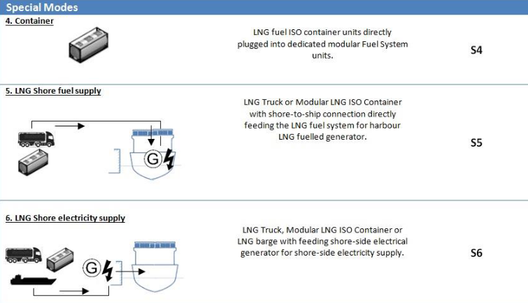
The definition used for LNG bunkering in the context of this Guidance allows these options to be also considered.
The concept followed is here that of the presence of LNG as a hazardous substance in the vicinity of the receiving LNG vessel. Whether the transfer operation occurs in the interface or not is only important for the detailed technical guidance. At the level of Risk & Safety and concept of operations the presence of LNG in the proximity of the LNG fuel receiving vessel.
Having codified the LNG supply options in the previous tables it is now further detailed how these options can influence the concept of operations inside the Port, which aspects can be challenging from PAAs perspective and, also, how these can possibly influence the Spatial Planning of the Port as an important responsibility of PAAs when accommodating for LNG bunkering in the port services portfolio.
| Table 5. LNG fuel supply options inside the Port area | ||
|---|---|---|
| LNG Supply Mode ((Code from Table 3 and 4) | Description | Observations/ Conditioning Factors |
| 1A1 | 1. LNG is brought to the Port area by truck. | Number of trucks to keep storage capacity can be significant, depending on the demand. |
| 2. Storage in pressurized or atmospheric tanks, inside the port. | Relevant if Port Area is large and LNG between storage and Receiving Ship is not viable by pipeline. | |
| 3. LNG is then loaded for TTS bunkering on a spot demand basis. Final movement of LNG inside the port by wheels. | Reduced LNG bunkering capacity (each truck will be able to deliver approximately 25 ton of LNG (in slightly less than an hour) – see below for more detailed information. | |
| 4. Bunkering by Truck-to-Ship from the storage and loading site. | Any potential variation-increase in bunkering demand would lead to an increase in the number of truck movements in the port area, both loading-on and loading-off. | |
| 5. Intermediate storage facilities used as buffer spot between supply of LNG and bunkering demand. | ||
| Nr. of LNG transfers inside the port: 3 | ||
| 1A2 | 1. LNG is brought to the Port area by truck | Loading-on by trucks and loading off by vessel is a very unlikely option accounting for the inflow/outflow balance. With very different capacities between truck LNG trailers and waterborne LNG transport (50 m3 against 500 to 5 000 m3, respectively). |
| 2. Storage in pressurized or atmospheric tanks, inside the port. | ||
| 3. LNG is then loaded for STS bunkering. Final movement of LNG inside the port area by ship/barge. | ||
| 4. Bunkering by Ship-to-Ship from the storage and loading site. | ||
| Nr. of LNG transfers inside the port: 3 | ||
| 1A3 | 1. LNG is brought to the Port area by truck | Loading of onsite storage facilities by truck is a very limited option to bring LNG fuel into the port area. |
| 2. Storage in pressurized or atmospheric tanks, inside the port. | For higher demands in LNG volumes it will represent a rather intense LNG tuck traffic into the port area with a consequently high rate of loading operations. | |
| 3. LNG is then transferred to the bunkering facility by pipeline onto a manifold, rigid arm or bunkering hose. | Limited pipeline length by need to reduce pressure increase in the line due to heat influx along the transfer pipeline (even if insulated). | |
| Nr. of LNG transfers inside the port: 2 | ||
| 1B1 | 1. Truck-to-Ship (TTS) directly to ship. LNG is brought to the Port in the same truck that will bunker the receiving vessel. | This is perhaps the most common method for LNG bunkering today, despite the very limited capacity and LNG bunkering rates available from TTS solutions (around 50-200 m3 and 40-60 m3/h). |
| 2. No fixed storage of LNG. | Despite the low capacity and bunker rates this is an option that allows flexibility and response to spot-demand. | |
| Nr. of LNG transfers inside the port: 1 | ||
| 2A1 | 1. LNG comes to the port by ship/barge, typically an LNG feeder vessel of higher capacity serving the intermediate logistical link between larger LNG import terminals and smaller LNG bunker facilities. | This represents an option that would allow high capacity and loading rates onto an intermediate storage tank within the Port, breaking this into smaller volumes for loading LNG trucks (or even multi-costumer hub), adding value to the port in terms of multi-service portfolio. |
| 2. LNG is loaded from the intermediate storage tanks onto LNG trucks for bunkering at designated location(s) inside the port. | Different LNG Bunkering operator can be involved if multi-operator loading from the storage site is allowed. | |
| Nr. of LNG transfers inside the port: 3 | Different designated LNG bunkering locations could be served allowing for flexible LNG bunkering response. | |
| 2A2 | 1. LNG comes to the port by ship/barge, typically an LNG feeder vessel of higher capacity serving the intermediate logistical link between larger LNG import terminals and smaller LNG bunker facilities. | This represents an option that would allow high capacity and loading rates onto an intermediate storage tank within the Port. |
| 2. LNG is loaded from the intermediate storage tanks onto smaller LNG bunker barges for bunkering at designated location(s) inside the port. | Different LNG Bunkering operator can be involved if multi-operator loading from the storage site is allowed. | |
| Nr. of LNG transfers inside the port: 1 | Different designated LNG bunkering locations could be served allowing for flexible LNG bunkering response. | |
| 2A3 | 1. LNG comes to the port by ship/barge, typically an LNG feeder vessel of higher capacity serving the intermediate logistical link between larger LNG import terminals and smaller LNG bunker facilities. | This is an inflexible method because the bunkering location must be close to the LNG storage tank(s) (≤ 250 m) [21]. Also, there may be conflicts with other activities taking place on the quay (i. e. loading/unloading of ships). |
| 2. LNG is transferred from storage tank location to bunkering facility by pipeline, either underground or above ground supports. | It is mainly indicated for situations with high bunker frequencies and small bunker volumes (e. g. supplying service vessels or scheduled ferry services). | |
| Nr. of LNG transfers inside the port: 2 | ||
| 2B2 | 1. LNG comes to the port area in the LNG bunker vessel/barge directly to bunker a waterborne receiving vessel, either at anchor or at berth. | This method is mainly used for large bunker volumes (100 to 20 000 m3) and high bunker frequencies, with the bunker vessel being supplied from a large import terminal or medium-sized bunker terminal. Bunkering can take place at the quay where the ship is berthed or at a specific anchorage in port or out at sea. The capacity of the bunker vessel and the bunkering rate applied must be tailored to the fuel needs of the ships being supplied. |
| 2. No intermediate storage in the port area. | This is a flexible method with which high bunkering rates can be achieved. The downsides are the high costs (initial investment and use) and possible interference with through traffic in the port. | |
| Nr. of LNG transfers inside the port: 1 | It is important that careful nautical analysis is made for the LNG bunkering location. For some ships bunkering by the outside may represent significant operational advantages, allowing the quay side for other possible operations. | |
| 3A1 | 1. LNG can be derived from pipeline into the Port area in 2 different ways: – Natural Gas pipeline into reliquefaction unit inside the port area. –LNG pipeline from outside the Port area, from close-by LNG Import Terminal outside the port. | This represents an option that would allow high capacity and loading rates onto an intermediate storage tank within the Port, breaking this into smaller volumes for loading LNG trucks (or even multi-costumer hub), adding value to the port in terms of multi-service portfolio. |
| 2. LNG stored in intermediate onsite pressure/atmospheric tanks within the port area. | Different LNG Bunkering operator can be involved if multi-operator loading from the storage site is allowed. | |
| 3. LNG loaded into LNG trailer trucks, for later bunkering at designated bunkering location. | Different designated LNG bunkering locations could be served allowing for flexible LNG bunkering response. | |
| Nr. of LNG transfers inside the port: 2 | ||
| 3A2 | 1. LNG can be derived from pipeline into the Port area in 2 different ways: – Natural Gas pipeline into reliquefaction unit inside the port area. – LNG pipeline from outside the Port area, from close-by LNG Import Terminal outside the port. | LNG bunkering via bunker vessel/barge is a solution for high capacity and high transfer rates. |
| 2. LNG stored in intermediate onsite pressure/atmospheric tanks within the port area. | Having a re-liquefaction facility onsite would allow flexibility in the production of LNG that would potentially be favourable to adjust the offer to the demand in peak demand periods. | |
| 3. LNG loaded into LNG bunker vessel/barge, for later bunkering at designated bunkering location. | This represents an option that would allow high capacity and loading rates onto an intermediate storage tank within the Port, breaking this into smaller volumes for loading LNG trucks (or even multi-costumer hub), adding value to the port in terms of multi-service portfolio. | |
| Nr. of LNG transfers inside the port: 2 | ||
| 3A3 | 1. LNG can be derived from pipeline into the Port area in 2 different ways: – Natural Gas pipeline into reliquefaction unit inside the port area. – LNG pipeline from outside the Port area, from close-by LNG Import Terminal outside the port. | This is an inflexible method because the bunkering location must be close to the LNG storage tank(s) (≤ 250 m) [21]. Also, there may be conflicts with other activities taking place on the quay (i. e. loading/unloading of ships). |
| 2. LNG stored in intermediate onsite pressure/atmospheric tanks within the port area. | The layout of de LNG pipeline will have an impact on spatial planning, dictating important local construction measures. | |
| 3. Transfer for bunkering location by LNG pipeline (short distance run). | Typical solution indicated for high bunkering rates and volumes. | |
| Nr. of LNG transfers inside the port: 1 | ||
| 3B1 | 1. In the case featured there is no intermediate onsite storage. LNG would come to the port area in liquid form, via special insulated pipeline. | This is an inflexible method because not only the bunkering location must be close to the LNG storage tank(s) (≤ 250 m) [21]. Bringing LNG into the port area by special insulated line would also mean that the LNG production would have to be very close to the port, representing several challenges in spatial planning. Should the LNG be sourced from another ship or barge berthed at a different quay, the challenges would be similar, in particular with the layout for the special pipelines. |
| Nr. of LNG transfers inside the port: 1 | ||
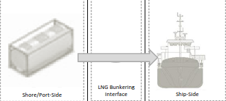
| S4 | 1. LNG fuel is here transferred to the receiving waterborne vessel via portable tanks. | The present Guidance includes bunkering by portable tanks within its scope. This is not the same approach followed in all LNG bunkering references where LNG fuel portable tanks are dealt as hazardous materials handling operations. In the context of the definition presented above of the present Guidance this is considered bunkering. Important note to make is that there is no correct way of classifying this, but aligning requirements for loading in and rolling in portable LNG containers should be in line with IGF Code requirements for these tanks onboard. Since the IGF Code deals with fuel, and not cargo, the operation of loading or rolling LNG fuel tanks, followed by their safe stowage and connection is here featured as an LNG bunkering option.x It will be important for the port to differentiate the handling of these containerized units from other containerized cargo. |
| 2. LNG portable tanks can be embarked loaded-in or rolled-in, if transferred in suspension by crane or embarked directly via truck, respectively. | The differentiation mentioned above should encompass: I. Bunkering location. II. Possible intermediate storage location for LNG portable tanks (safe area in the quay side). III. Possible limitations in the loading/rolling in operation accounting for other operations. | |
| Nr. of LNG transfers inside the port: 0 (LNG transfer occurs inside the ship) | ||
| S5 | 1. LNG can be supplied to an LNG fuelled waterborne vessel whilst at berth, directly from an LNG trailer tank, ISO portable container or even barge to an LNG fuel burning unit onboard. | This operation is mentioned throughout the Guidance as «LNG fuelling» but, in fact, it consists of a bunkering operation scoped within the definition presented above. The challenges presented to this type of operation are similar to the LNG fuel transfer operation, with the additional concern that the LNG storage stands outside, close to the vessel in a location that is, otherwise, not a fuel storage location. |
| 2. The LNG would, in this case, be fed through an Evaporator onboard onto the gas fuelled unit (engine, boiler…) at the exact consumption rate of that unit. | The interesting aspect of this option is that ships can improve their environmental performance whilst at berth without having to invest in onboard LNG storage or complex fuel systems. | |
| 3. The LNG truck, portable tank or barges are used in this option as LNG temporary storage unit for the receiving ship whilst at berth. | The challenge is that, whilst LNG fuel storage spaces onboard are regulated by the IGF Code, it is not the same case outside the ship and, therefore, also outside the scope of the IGF Code. | |
| S6 | 1. In this case, electrical energy is supplied to the receiving vessel, not LNG. | This operation is by far the one the most different from typical LNG bunkering operation and, in fact, LNG is never transferred to the receiving vessel. The most relevant aspect to take into account, this special situation S6 is the fact that a small LNG power plant is close to the receiving vessel, either alongside or in the vicinity of the receiving vessel. |
| 2. LNG fuel is used by power generation units, or small-scale power plants, that will provide electrical shore-side energy to the receiving vessel. | It represents an important application of LNG energy, adding value to the Ports environmental performance and, also, allowing ships to meet air emissions requirements whilst at birth. | |
LNG Bunkering Modes
Delivering LNG fuel to a ship can be done in different ways, following different methods, depending on different logistic and operational factors. Various LNG bunkering methods are available, with Truck-to-Ship (TTS) being the most commonly used. Today’s choice for TTS method has been a result of different aspects and difficulties that concur in the development of the business case for bunkering LNG as a marine fuel. On one hand the operational flexibility and limited infrastructure requirements for TTS and, on the other hand, relatively low initial investment to establish business readiness, have driven the option for this LNG bunkering method. The table below covers the relevant possible methods of bunkering LNG fuelled vessels.
| Table 6. LNG bunkering methods | |||
|---|---|---|---|
| Method | Typical Volumes (V) and Bunker Rates (Q) | Advantages | Disadvantages |
| Truck-to-Ship – TTS LNG truck connected to the receiving ship on the quayside, using a flexible hose, assisted typically by a hose-handling manual cantilever crane. | V ≈ 50 – 100 m3 | Operational Flexibility | Limited capacity of trucks: approximately 40 – 80 m3 is likely to dictate multi truck operation. |
| Q ≈ 40 – 60 m3/h | Limited Infrastructure requirements | Limited flow-rates (900 – 1 200 l/hr) | |
| Possibility to adjust delivered volumes (nr. of trucks) to different client needs. | Significant impact on other operations involving passengers and/or cargo | ||
 | Possibility to adapt to different safety requirements. | Limited movement on the quay-side, mostly influenced by the presence of the bunker truck(s). | |
| Possibility to serve different LNG fuel users on point topoint delivery | Exposure to roadside eventual limitations (permitting, physical limitations, traffic related, etc.) | ||
| Ship-to-Ship – STS LNG is delivered to the receiving vessels by another ship, boat or barge, moored alongside on the opposite side to the quay. LNG delivery hose is handled by the bunker. | V ≈ 100 – 6 500 m3 | Generally does not interfere with cargo/passenger handling operations. Simultaneous Operations (SIMOPS) concept is favoured. | Initial investment costs involving design, procurement, construction and operation of an LNG fuelled vessel/barge. |
| Q ≈ 500 – 1 000 m3/h | Most favourable option for LNG bunkering, especially for ships with a short port turnaround time. | Significant impact in life-cycle cost figures for the specific LNG bunker business. | |
| Larger delivery capacity and higher rates than TTS method. | Limited size for bunker vessel, conditioned by port limitations. | ||
 | Operational flexibility – bunkering can take place alongside, with receiving vessel moored, at anchor or at station. | ||
| Terminal (Port)-to-Ship-PTS LNG is either bunkered directly from a small storage unit (LNG tank) of LNG fuel, small station, or from an import or export terminal. | V ≈ 500 – 20 000 m3 | Possibility to deliver larger LNG volumes, at higher rates. | From operational perspective it may be difficult to get the LNG fuelled receiving vessel to the Terminal. |
| Q ≈ 1 000 – 2 000 m3/h | Good option for ports with stable, long-term bunkering demand. | Proximity of larger LNG terminal may not be easy to guarantee. | |
| Calculation of available LNG for delivery, in small storage tanks, can be difficult unless pre-established contract exist. | ||
| ISO Container-to-Ship LNG can also be delivered to the receiving vessel by embarkation of ISO containerized LNG tanks. If the receiving vessel is pre-fitted with LNG connections the fuel can then be used. | Typical capacity: | Absence of interface bunkering operations. | Connections onboard need to comply with strict construction regulations. |
| ISO 20 ft: 20,5 m3 | Simplification by exempting operations from hoses and other operational aspects. | Limited volumes available in 20 – 40 m3 containers. | |
| ISO 40 ft: 43,5 m3 | Potential advantages from intermodal possibilities. | Only suitable for a limited type of ships. | |
 | Leveraging of intermodal transportation. | Requires pre-installation of LNG fuel installation. | |
Depending on the LNG quantity needed and potential time constraints for the operation it is possible that different LNG bunkering modes are more applicable to different needs, from different ship types, operational profiles and LNG fuel onboard storage capacities. Very likely larger ships, that potentially make use of LNG for longer voyages, will naturally require larger bunker volumes and, inevitably higher bunker rates. This is very likely the potential LNG bunkering characteristics for Very Large Container Ships, who stay at berth for the shortest time interval possible whilst potentially requiring the largest volumes of LNG bunkering. A suitable LNG bunkering method should therefore be provided for such needs. In addition to the capacity challenge.
| Table 7. Typical LNG bunkering per different generic ship type | |||||
|---|---|---|---|---|---|
| Vessel Type (Receiving vessel) | Bunker Quantity | Rate | Duration | Hoses or arm diameter (pol) | Adequate Bunkering Mode |
| Service vessels, tugboats, patrol boats and fishing boats. | 50 m3 | 60 m3/h | 45 min | 2×2” or 1×3” | TTS |
| Small Ro-Ro and Ro-Pax vessels. | 400 m3 | 400 m3/h | 1 hr | 2×4” or 1×6” | TTS/ STS |
| Large Ro-Ro and Ro-Pax vessels. | 800 m3 | 400 m3/h | 2 hr | 2×4” or 1×6” | STS |
| Small cargo, container and freight vessels. | 2 000 – 3 000 m3 | 1 000 m3/h | 2 to 3 hr | 2×8” or 1×12” | STS |
| Large freight vessels. | 4 000 m3 | 1 000 m3/h | 4 hr | 2×8” or 1×12” | STS |
| Large tankers, bulk carriers and container ships. | 10 000 m3 | 2 500 m3/h | 4 hr | 2×10” | STS/PTS |
| Very large container ships and oil tankers. | 20 000 m3 | 3 000 m3/h | 7 hr | 2×12” | STS/ PTS |
All LNG bunkering modes share several fundamental aspects of concern that need to be carefully addressed in order to have safe and successful operations:
- Risk Analysis and Safety Management, intrinsically different depending on the method chosen for bunkering.
- Permitting, which will be needed for the different operations, from the relevant competent authorities.
- Training of all personnel involved, both onboard and ashore.
LNG Bunkering Equipment, Ships and Infrastructure
As identified in the previous sections, LNG bunkering can assume very different shapes in terms of LNG supply chain and LNG bunkering mode. This will relate to the particular aspects of bunkering location, receiving LNG vessel characteristics and BFO service portfolio. Inherent to the different bunkering options and modes it is possible to consider different equipment, ships and infrastructure elements that compose the different LNG bunkering solutions.
LNG Bunkering relevant Equipment and Infrastructures
LNG Feeder Vessels
LNG feeder vessels are small to medium-sized LNG carriers used for regional transport of LNG with a view to its use as ship fuel or the industrial use of natural gas in remote places. LNG feeder vessels currently in operation or under construction are double-hulled gas carriers with a capacity of 7 500 – 30 000 m3. The size and main dimensions of the vessels will depend on market demand and the physical limitations of the intended unloading location, such as dimensions of the berthing site and draught at the jetty. The figures below show some examples of LNG feeder vessels with different capacities.
LNG feeder vessels can be loaded at large LNG import terminals. Loading takes place via fixed cryogenic pipes and flexible hoses or fixed arms at the typical rate of 1 000 – 6 000 m3/h (depending on the size of the feeder vessel). The LNG vapour displaced from the ship’s cargo tanks is returned to the terminal via a vapour return line.
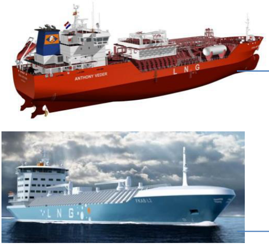
Unloading of the vessel at a bunker terminal or bunkering station is also done using fixed cryogenic pipes and flexible hoses or fixed arms. The LNG is pumped to the terminal by the submersible pumps fitted in the ship’s cargo tanks at a typical rate of 1 000 – 6 000 m3/h.
LNG Bunker Vessel
LNG bunker vessels are small LNG ships used for the direct supply of LNG fuel to ships inside or outside a port. During bunkering, the LNG is pumped from the bunker vessel’s cargo tanks directly into the fuel tanks of the ship being supplied. LNG bunker vessels are identical in design to LNG feeder vessels and typically have a capacity of 500 – 20 000 m3/h.
LNG bunker vessels represent today a key role in the ability of LNG bunkering to grow in capacity whilst avoiding the difficulties of shore side/quay operation. Bunkering from the opposite side to the quay will allow to design bunkering an port operation in a more flexible.
Small LNG bunker vessels (500 – 3 000 m3) are usually equipped with one or two cargo tanks. These are mainly cylindrical cargo tanks with a design pressure of 3 to 4 barg (IMO type C tank) and an individual tank capacity of 500 – 2 000 m3 of LNG.
LNG bunker vessels can be loaded at small to medium-sized bunker terminals or large LNG import terminals. Loading takes place via fixed cryogenic pipes and flexible hoses or fixed loading arms at a rate of 200 – 3 000 m3/h (depending on the size of the bunker vessel). Bunkering is done using flexible hoses or fixed arms at a rate of 60 – 3 000 m3/h depending on the size of the fuel tanks on the receiving vessel.
Rules applicable to LNG bunker vessels are typically IGC Code unless the bunker vessel is operating only in inland waterways, outside the scope of IMO IGC Code applicability. Here the applicable instruments would be defined at National Administration level. In the EU context the ADN agreement, Directive 2016/1629 or RVIR regulation would apply. Details of certification elements required for barges included in Section 15* of the present Guidance.
LNG Bunker Barge
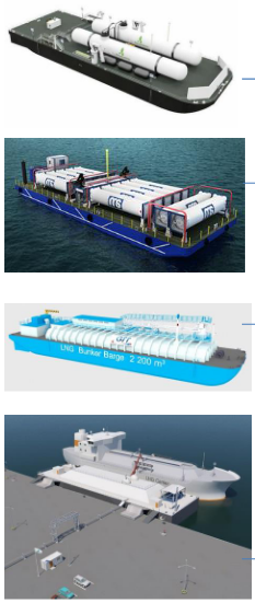
LNG Bunker Barges are, essentially, the non-propelled version of LNG bunker vessels. All types of different LNG capacities and containment systems are possible, with a growing number of designs being developed.
Mobility of these barges is subject to push-pull tug arrangements or to any other external propelling unit that deliver the barge the ability to be moved around the port area, responding to different LNG bunkering needs in potential different LNG bunkering locations.
LNG bunkering service
The use of a tug or external unit for mobility represents, on one hand, a clear flexible option that allows moving different floating units with one propelling craft. On the other hand, it may represent a challenge for manoeuvrability in higher traffic waterways.
Barges can have integral LNG tanks or, as in the cases presented in the figures to the left, tanks above main deck. Whilst rules have been developed for LNG bunker vessels, mostly derived from IGC Code and IGF Code Codes, barges seem not to have a dedicated of of rules that apply directly to the carriage LNG fuel and bunkering services In general, barges intended for the carriage of liquefied gases in bulk are to comply with the International Code for the Construction and Equipment of Ships Carrying Liquefied Gases in Bulk (IGC Code) as appropriate, or other national standard, as applicable to the non-propelled status of the vessel. A special certificate attesting to the degree of compliance with the above codes or national standard may be issued upon request. For manned barges, consideration is to be given for full compliance with the code. In all cases, it is the Owner’s responsibility to determine the requirements of flag Administration and port Administration.x. This may impose a challenge in the harmonization of these floating craft that should be taken into consideration by PAAs.
Details of certification elements required for barges included in Section 15* of the present Guidance.
LNG IMO Tanks/Containment Systems
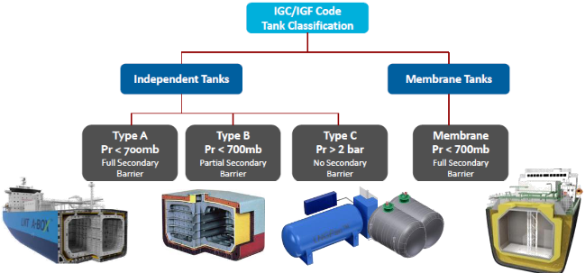
For the cargo tanks used on gas carriers, a distinction is generally made between non-self-supporting tanks (atmospheric membrane tanks) and self-supporting tanks (actual pressure tanks). The self-supporting cargo tanks are subdivided into three classes according to their strength. The same classification (IMO Classification) is used for LNG fuelled ships, to define the LNG fuel tanks.
IMO TYPE A TANK
These are prismatic cargo tanks with a low design pressure (< 0,7 barg). The material used in the construction of these tanks offers insufficient resistance to crack propagation, so that for safety reasons a second shell (tank wall) has to be provided to contain any leaks. This second shell can also be formed by parts of the ship (e. g. inner hull) provided that these are capable of resisting the low temperature of the cargo.
IMO TYPE B TANK
These are prismatic or spherical cargo tanks with a low design pressure (< 0,7 barg), for which a great deal of attention has been paid in the design phase to detailed stress analyses (inter alia in relation to fatigue and crack propagation).
Spherical Moss-Rosenberg tanks are the best known example of this type of tank. Because of the improved design, a type B cargo tank only needs to have a partial second shell, fitted on the underside of the tank in the form of a drip tray.
IMO TYPE C TANK
These are spherical, cylindrical or bilobe pressure tanks with a design pressure greater than 2 barg. The tanks are designed and built according to the conventional pressure vessel codes and, as a result, can be subjected to accurate stress analyses. Moreover, in the design phase much attention is paid to eliminating possible stresses in the tank material. For these reasons, type C cargo tanks do not require a second shell.
For ships in which the cargo is transported in a cooled and partially pressurised state, the cargo tanks and associated apparatus are typically designed for a working pressure of 4 to 6 barg and a vacuum of 0,5 bar.
The cargo tanks are typically insulated with polystyrene or polyurethane panels attached to the tank wall.
Membrane Tank
The inner surface of the insulation is exposed to the cargo. – Membrane tank – Membrane tanks are not-self-supporting tanks which consist of a thin layer (membrane) supported through insulation by the adjacent hull structure.
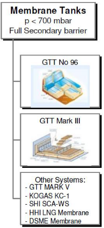
Despite the fact that membrane tanks are today widely used in LNG cargo tankers, the application of these technologies for LNG as Fuel is still without much expression.
Membrane tanks, as in Type A or B, optimize holding time by improved insulation.
LNG Trucks
Regional transport and local distribution of LNG can also be performed using LNG trucks provided that the distance between the loading and unloading locations is not too great (max. 500 km) and the consumption of the local consumer is small.
top, LNG truck bunkering with second truck-trailer for Nitrogen/Inert
Gas supply. Below 2 (two) LNG trucks bunkering back-to-back via
common 2-way manifold derivation
The capacity of LNG trucks varies from 35 to 56 m3 for conventional trucks and up to 80 m3 for a truck/trailer combination. As an alternative to trucks, ISO tank containers with a capacity of 21 m3 (20” container) or 45 m3 (40” container) can also be used. In some countries there may be a restriction on the maximum authorised mass (MAM) Maximum authorised mass (MAM) means the weight of a vehicle or trailer including the maximum load that can be carried safely when it’s being used on the road. This is also known as gross vehicle weight (GVW) or permissible maximum weight. It will be listed in the owner’s manual and is normally shown on a plate or sticker fitted to the vehicle. The plate or sticker may also show a gross train weight (GTW), also sometimes called gross combination weight (GCW). This is the total weight of the tractor unit plus trailer plus load.x of trucks used for domestic transport.
In terms of cargo tank design, LNG trucks can be divided into two types:
- Trucks with a single-walled cargo tank made of stainless steel, insulated with insulating rigid polyurethane panels and fitted with a thin aluminium or stainless-steel protective cover (The use of single-wall trucks for domestic transportation of LNG is not allowed in some countries due to concerns about the fire safety of these trucks given the flammable nature of the insulating material.);
- Trucks with a double-walled vacuum-insulated cargo tank comprising an inner tank made of aluminium or stainless steel and an outer tank of carbon steel. The space between the inner and outer tanks is a vacuum and is further insulated with perlite, glass wool or a super-insulating foil.
The cargo tank of an LNG truck typically has a design pressure of 5 to 6 barg and is equipped with a redundant overpressure protection system with two safety valves.
The main specifications of LNG trucks are presented below. The pressure and temperature of the LNG in the truck during transportation is typically between 0 and 3 barg (-160 °C and -142 °C).
| Table 8. General specifications of LNG trucks | |
|---|---|
| Volume | 35 – 56 m3 (14 – 23 tonnes of LNG) |
| Maximum Filling % | Max. 90 % |
| Design pressure (test pressure) | 5-6 barg (9 barg) |
| Set pressure of safety valves | typically 5-6 barg |
LNG trucks can be loaded at large LNG import terminals or medium sized bunker terminals at a rate of 50 – 100 m3/h. The LNG is pumped from the LNG storage tanks into the truck using a submersible pump via a fixed cryogenic pipe and a flexible (un)loading hose. The displaced LNG vapour is returned to the storage tanks via a vapour return line.
Unloading of LNG trucks at a bunker terminal or local bunkering station is also done using a flexible hose (2-3”) and a fixed cryogenic pipe at a typical rate of 40 to 60 m3/h. The LNG can be transferred using a pump fitted on the truck or by raising the pressure in the truck using a pressure build-up coil or a connection to an external nitrogen or natural gas network.
LNG Truck Common Bunkering Manifold
As LNG bunkering demand increases, the capacity of LNG truck (both in terms of volumes or LNG transfer rates) becomes insufficient. To continue using LNG trucks for TTS bunkering, the option found to increase volumes and transfer rates and optimize LNG bunker delivery operation times includes today common manifold structures as the one presented in the figure to the left.
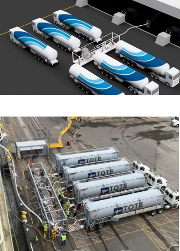
The option for common manifolds has been first featured in IACS Rec. 142 where it is mentioned: Depending on the shore side arrangement it may be possible to increase the bunker rate to some extent by simultaneous bunkering from multiple trucks via a common manifold.
Adequate and detailed operating procedures are important for safety of the operation. All the steps (preparation, pre-bunkering, bunkering, post-bunkering should be carefully detailed and explained. The risks and safety of the whole operation should be carefully assessed, not only in terms of HAZID and HAZOP analysis for the LNG bunkering operation, but also on the implications for the LNG bunkering location.
ISO LNG Tanks
ISO LNG Tanks are elements with the potential to play an important role in the LNG fuel value chain, not only as cargo but also as fuel. With the following typical capacities:
- ISO 20 ft: 20,5 m3;
- ISO 40 ft: 43,5 m3.
With the possibility of LNG IMO Tanks/Containment Systemsportable fuel tanks to be used as LNG fuel units included in the IGF Code (IGF Code Section), it is possible to consider the use of these elements as fuel storage for ships converted to LNG as fuel that did not make use of the hull internal volume to place fixed LNG fuel storage.
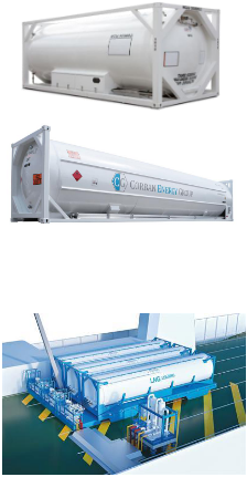
representation of the LNG FuelPac ISO concept from Wartsila with ISO
portable tanks, «plug-in» common manifold and evaporator on deck
A normal tank container intended for transporting LNG cannot, however, be used directly as a portable fuel tank since it does not fulfil all the requirements for marine LNG fuel tanks.
Standart ISO frame.
Compliance with transportation regulations (IMDG, TPED, ADR, RID, CSC among others).
Only the first two requirements are required for ISO LNG tanks. Remaining aspects to be covered for LNG portable tanks.
- Compliance with rules for use as LNG fuel tank on board ships.
- IMO Type-C tank.
- Water spraying system.
- Tank safety relief valves designed for fire case.
- Connection to external vent mast.
- LNG leakage detection and protection.
- Class approved equipment & design.
- Stainless steel outer shell.
- Dry disconnect quick couplings.
- Connections at end for connecting to ship.
- Connection to automation system on the ship.
- Connection to safety systems on the ship.
Rigid/Mechanical arms
Whilst smaller diameter 2 to 3” LNG hoses are easily handled by hand, larger diameters are far more difficult to handle. The use of dedicated, or general purpose, cranes have therefore been of great assistance in the operation of LNG hoses for connection with the LNG receiving vessel.
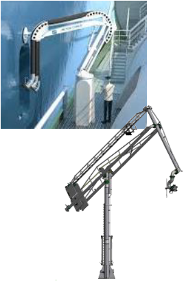
handling with dedicated saddle articulated points and 2) Example of a
full articulated mechanical LNG bunker arm
In addition to the support of LNG hoses weight during bunkering, other aspects are important drivers for the use of mechanical rigid LNG bunkering arms:
- Safety of the whole LNG bunkering operation.
- Precision in the connect/disconnect procedure.
- Optimization of bunkering duration.
- Possibility to deliver LNG bunker connection at different heights.
Full rigid arms are provided with rigid insulated pipe sections through which LNG is pumped through to the receiving vessel. Swivel joints allow the necessary motion in the intended degrees of movement, whilst pneumatic/hydraulic assisted mechanisms provide the motion and binary forces for the mechanic arm.
Typical installations for such arms would be LNG bunkering fixed stations or LNG bunker vessels.
LNG bunkering stations
Local jetties can be equipped with a small-scale LNG Technical requirements for LNG bunkering systems on shipsbunkering station that is used to supply specific end users (e. g. service vessels or ferries). The storage capacity of such bunkering stations is typically 100 to 3 500 m3. Bunkering takes place by means of a fixed bunkering installation (i. e. a cryogenic pipe and loading arm or flexible hose) from the stationary LNG storage tanks at a rate of 50 – 500 m3/h depending on the size of the vessel being supplied.
Such stations are generally supplied by small LNG ships (capacity: 500 to 3 000 m3) or LNG trucks that bring the LNG from a nearby LNG bunker terminal or from a large LNG import terminal. A possible alternative to supplying LNG by ship or truck is to build a small-scale liquefaction unit with a capacity of 5 000 to 20 000 tpa in the immediate vicinity of the station.
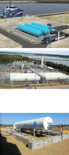
bunkering installations, both with 3 horizontal pressure tanks. The one
below representing an LNG trailer installed temporarily, with concrete defences
The figures to the left show some examples of small-scale LNG stations.
Whereas the two figures on the top are demonstrative of small-scale fixed LNG bunkering stations, the one on the bottom is intended to demonstrate what can be achieved through a temporary installation of an LNG trailer, on a semi-fixed installation. It is important that PAAs are aware that even if this situation is not a fixed installation, similar concerns should be considered. The use of LNG trailer trucks in semi-fixed LNG bunkering installations should not represent a way to avoid more stringent regulatory requirements for fixed small scale LNG bunkering sites.
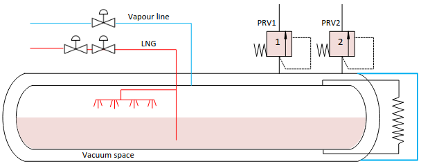
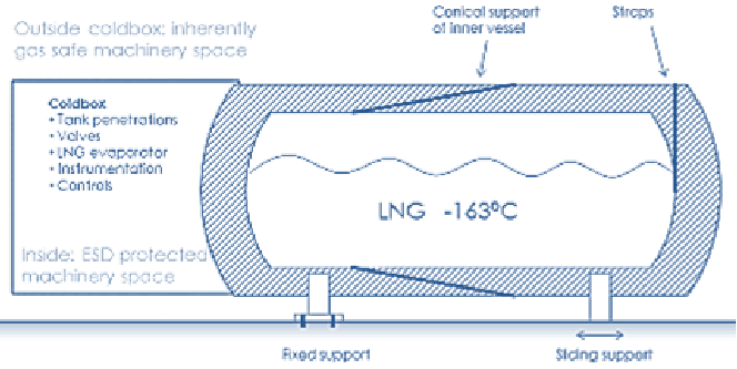
The figure below shows a schematic representation of a vacuum-insulated LNG tank.
The storage tanks used at a local LNG bunkering station are typically cylindrical tanks with a volume of 100 to 1 000 m3. More specifically, they are double-walled vacuum insulated pressure tanks set up either horizontally or vertically. The degree of filling of the tanks must not exceed 95 % under any circumstances, in line with ADR requirements.
The LNG is stored in the tanks at a pressure of 0 to 4 barg and a temperature of -160 °C to -138 °C. Because the tanks are vacuum-insulated, little heat is lost through the tank wall and the tank pressure will only rise very gradually during long periods when no LNG is withdrawn. The tanks are also fitted with an ambient air vaporiser to keep the tank pressure at the desired level as well as a redundant overpressure protection system with two safety valves.
The characteristics dimensions of such tanks are given in the table below.
| Table 9. Typical characteristic dimensions for LNG storage pressure tanks | ||||
|---|---|---|---|---|
| Tank Volume | 100 m3 | 250 m3 | 500 m3 | 700 m3 |
| Diameter | 3,5 | 4,3 | 5 | 5,5 |
| Length | 16,5 | 23 | 30 | 35 |
| Max. connection (mm) [inches] | (100) [4] | (150) [6] | (150) [6] | (200) [8] |
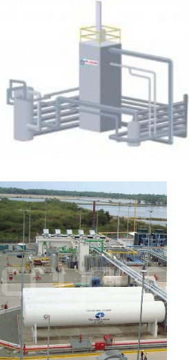
The ship bunkering installation is similar to the installation used to unload LNG ships, namely a fixed cryogenic pipe and a flexible hose or loading arm. The flow rates applied when bunkering vessels using a fixed installation are typically 50 to 500 m3/h depending on the size of the ship being supplied.
Fixed LNG bunkering stations can be loaded both from ships or trucks:
- Loading from LNG ships: LNG ships unloaded at a bunkering station have a typical capacity of 500 to 3 000 m3 and unloading takes place via a fixed arm or a flexible hose at a rate of 200 – 1 000 m3/h. The diameter of the unloading arm or hose used for this purpose is 4” to 8”. The LNG is transferred to the storage tank via a cryogenic unloading pipe with a diameter of 4” or 10”. The unloading pipes must be kept as short as possible (<250 m) to minimise boil-off gas losses and associated pressure increase in the LNG line.
- Loading from LNG ships: The LNG trucks used to supply the station are generally unloaded at a rate of 40 – 60 m3/h using a flexible unloading hose (3”) and a cryogenic LNG pipe (3”/4”). The LNG can be transferred using a pump fitted on the truck or by raising the pressure in the truck using a pressure build-up coil.
Liquefaction units
Building a small to medium-sized liquefaction unit is a possible alternative to shipping in LNG to bunker terminals and bunkering stations. Such liquefaction units have a production capacity of 5 000 to 20 000 tpa (for bunkering stations) and 40 000 to 300 000 tpa (for bunker terminals). Medium-sized liquefaction units typically have a production capacity of 270 to 2 000 m3 of LNG per day, which implies a natural gas consumption of 7 200 to 54 000 m3 (n)/h.
Small liquefaction units typically have a production capacity of 35 to 135 m3 of LNG per day, which implies a natural gas consumption of 900 to 3 600 m3 (n)/h.
For LNG liquefaction units with a capacity of 5 000 – 300 000 tpa, the following process cycles are mainly used:
- an open cycle with turboexpander;
- a closed one- or two-stage cycle with nitrogen refrigerant;
- a closed one- or two-stage cycle with mixed refrigerant.
LNG (re)-liquefaction plants are important infrastructure elements that allow both production of LNG onsite and Boil-Off Gas management through re-liquefaction.
LNG pipeline (fixed installations)
LNG pipelines are increasingly important elements in the context of LNG bunkering. They allow the LNG fuel to be transferred from the storage location (pressure or atmospheric tanks) into the LNG bunkering location.
The total length of the pipelines is limited to the efficiency of the insulation and, in principle, should not be longer than 250 m. This will depend on many aspects which are mostly local-dependent and whether the LNG distribution system has the ability to manage BOG generated during transfer.
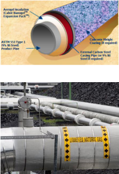
representation, highlighting the insulation layer and, below, LNG
pipeline above ground (to be noted the apparent large diameter mostly
due to insulation. Outer layer for physical protection and to avoid
moisture frost formation
The LNG pipeline layout design can consider different routing solutions, either by aerial route with supports or lay along a special trench, designed to keep the LNG pipeline offset from the risks associated to vehicle circulation hazards/accidents.
LNG pipelines are then able to feed either local numbering manifolds or directly into mechanical articulated arms as the one above.
Whenever LNG pipelines are routed, aerial, over ground or underground, crossing public domain spaces, careful consideration must be paid to Safety with special dedicated measures and barriers to mitigate the risk of hazardous events affecting the pipeline.
Inerting arrangements to be part of the LNG bunkering station. LNG pipeline to be permanently inerted outside LNG bunkering operation.
LNG hoses
LNG bunkering hoses are important elements in the LNG bunkering operation. Typically in composite multi-layer thermoplastic, LNG hoses are to be designed and certified according to the following standards:
- EN 1474-2 – Design and testing of marine transfer systems. Design and testing of transfer hoses.
- EN 13766:2010 – Thermoplastic multi-layer (non-vulcanized) hoses and hose assemblies for the transfer of liquid petroleum gas and liquefied natural gas – Specification.
Typically, the bunker hose is expected to be provided by the supplier. It should be suitably long and flexible, such that the hose can remain connected to both the supplier’s manifold and the receiving ship’s manifold during normal relative movements expected from wind, waves, draft changes, current, and surges from passing vessels. Typically, bunker hoses are constructed of composite materials and are flexible to allow for relative movements. The supplier should provide a bunker connection at the hose end that will match the receiving ship’s connection. Although industry standardization has not yet been implemented, ISO/TS 18683:2015 references relevant standards.
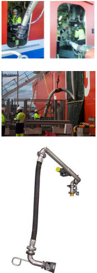
applications. Top to bottom: 1) Bunkering of the MV Viking Grace with
bunker hose handled from the bunker vessel side; 2) LNG bunkering
hose suspended from crane line, noting the attention to the hose
suspension point where pressure is distributed along the saddle
curvature; 3) example of a hybrid rigid-flexible LNG bunkering line
arrangement
Additionally, the hose should be capable of releasing without damage or significant spills if the relative position or movement of the receiving ship exceeds the limits. LNG bunker hoses are typically fitted with connections that are of the quick connect type and remain sealed until the connection (drip-free type) is made. The receiver’s end of the hose also will usually be fitted with an emergency release system (ERS), such as a drip-free, breakaway coupling that gives way before excessive pull causes the hose to break or other damage to occur.
Read also: LNG Bunkering Guide – What It Is and How to Use It
This type of coupling uses spring loaded shutoff valves to seal the break and stop any LNG or vapour release. Quick connect and break-away couplings are readily available in the market and minimize the possibility of LNG leakage and gas escape.
Cranes, loose gear, supports, etc., are to be provided for hose handling and bunkering operations and are to be designed, arranged and surveyed in accordance with the applicable requirements of the ABS Guide for Certification of Lifting Appliances.
Hose supports or cradles are to be used where necessary to keep hose bends within the design limits, as per manufacturer’s recommendations.
Fixed LNG bunker transfer systems are to be designed and tested in accordance with recognized standards such as EN1474-3 (offshore transfer system) and/or EN1474-2 (transfer hoses). LNG bunker transfer systems and hoses are to be arranged to provide sufficient flexibility over the range of expected relative vessel motions.
Hoses can also be part of hybrid flexible/rigid/mechanical systems, such as the one presented to the left. ERC and connector to be also fitted at the end.
Emergency Release System (ERS)
The present Guidance refers to ERS, ERC and ESD in the terms presented in EN ISO 20519, where ERS is defined as a system comprised of two sub-systems/elements that allow the main functional requirement of quick/dry disconnect during bunkering operation, as a consequence of an emergency.
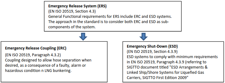
Emergency Shut-Down (ESD)
An emergency shut-down (ESD) is a method or a system that safely and effectively stops the transfer of LNG (and vapour as applicable) between the LNG bunkering facility and the receiving ship in the event of an emergency during the bunkering operation. The control systems involved in the ESD, which is a linked system to allow both parties (on board receiving ship and the bunkering facility) to shut down the transfer in an emergency situation, can be activated automatically or manually.
The ESD may consist of two parts:
- ESD-stage 1, is a system that shuts the LNG transfer process down in a controlled manner when it receives inputs from one or more of the following; transfer personnel, high levels LNG tank alarms, cables or other means designed to detect excessive movement between transfer vessels or vessel and an LNG port facility, or other alarms.
- ESD-stage 2, is a system that activates decoupling of the transfer system between the transfer vessels or between a vessel and an LNG port facility. The decoupling mechanism contains quick acting valves designed to contain the contents of the LNG transfer line (dry break) during decoupling.
The figure below presents a possible integrated diagram for an ESD, for the specific case of TTS ESD bunkering.
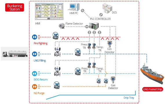
ESD systems to comply with minimum requirements in EN ISO 20519, Paragraph 4.3.9 (referring to SIGTTO document titled «ESD Arrangements & Linked Ship/Shore Systems for Liquefied Gas Carriers, SIGTTO First Edition 2009».
Typical reasons for activation of the ESD include the following:
- Gas detection.
- Fire detection.
- Manual activation from either the supplier or receiver.
- Excessive ship movement.
- Power failure.
- High level in receiving tank.
- Abnormal pressure in transfer system.
- High tank pressure.
- Excessive stress in LNG bunker arm.
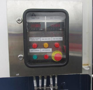
Other causes as determined by system designers and regulatory organizations.
Emergency Release Coupling (ERC)
A breakaway coupling or emergency release coupling (ERC) is a coupling located in the LNG transfer system (at one end of the transfer system, either the receiving ship end or the bunker facility end, or in the middle of the transfer system), which separates at a predetermined section when required, each separated section containing a self-closing shut-off valve, which seals automatically.
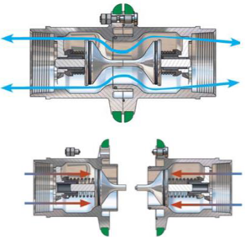
tight together, during normal operation and, below, after emergency release for dry breakaway
ESD systems to comply with minimum requirements in EN ISO 20519, Paragraph 4.3.9 (referring to SIGTTO document titled «ESD Arrangements & Linked Ship/Shore Systems for Liquefied Gas Carriers, SIGTTO First Edition 2009».
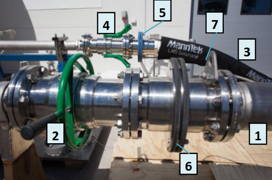
where:
- 1 – LNG bunkering line.
- 2 – Main Quick-Connect/Dry Disconnect coupling (QC/DC).
- 3 – Vapour return line.
- 4 – Return QC/DC.
- 5 – ERC main line.
- 6 – ERC Vapour Return.
- 7 – Pad-eye for LNG bunkering hose crane handling.
Dry Quick-Connect/ Disconnect Coupling
Dry Quick Connect/Disconnect couplings (Dry QC/DC) are a specific type of couplings that allow easy connection/disconnection without the use of manual intensive operation (such as tightening bolts), whilst including self-containing stop valves at the female and male ends to avoid spillage of hose and receiving line LNG content that may possibly be contained in the lines (if not inerted).
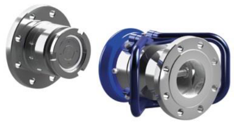
The coupling consists of a Nozzle (male) and a receptacle (female). The nozzle allows quick connection and disconnection of the fuel supply hose to the receptacle, mounted on the LNG manifold. Connectors used shall be designed to operate as quick connect/disconnect couplings. Couplings, in nominal sizes up to 6”, for flows up to 650 m3/h, and maximum flow rates of 10 m/s.
The advantages of standard quick connectors are as follows:
1 Avoid mix-up and use of any connector designed for other fluids or gasses through the safety of a unique standard geometry.
2 Allow for a quick and easy mechanical solution with efficient and safe connection specially designed for cryogenic LNG.
3 Avoid company standards that will normally be protected by property rights and may be limited to contracts and brand distributors, which normally results in less competition and hamper public procurement.
4 Prevent the safety risk of fitting additional adaptors and gaskets to convert between different company standards and the risk of using parts not adequate for cryogenic fluids.
5 Avoid the temptation to make or modify adaptors, to fix something on short notice, with possible limited access to the right material and manufacturing equipment.
6 Eliminate the need for manual bolting and manual re-tightening after down-cooling to cryogenic temperatures.
7 Avoid leaks (methane slip) and problems due to uneven tightening and any accident if wrong studs accidentally have been used.
8 Avoid torsion problems as the connectors have swivel features and thus torsion problems that may arise on flanges do not exist.
9 Ensure conformant operation and safety training for all personnel involved in bunkering on a world-wide basis.
ESD systems to comply with minimum functional requirements in EN ISO 20519, Paragraph 4.3.
NOTE:
Until the adoption of an International Standard for Dry QC/DC couplings the Best Practice to follow is:
- Ensure compliance of the couplings with the Functional Requirements in EN ISO 20519.
- Consult with Classification Society on the best options to optimize LNG bunkering compatibility with receiving vessel.
- Liaise with Industry Association (such as SGMF) or other in order to get the best.
Isolation Flange
Vessels transferring or receiving low flashpoint flammable liquids, such as LNG, need to take additional precautions against ignition resulting from electrical arcing.
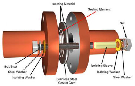
Two causes of arcing are:
- Static electricity build-up in the LNG bunker hose.
- Differences in potential between the ship and bunker supplier’s facility, including the quay or pier, trucks, bunker vessels, etc.
An effective way of preventing arcing is to isolate the ship and the bunker supplier using an isolating (insulating) flange fitted at one end of the bunker hose only, in addition to an electrically continuous bunker hose. The isolating flange, an example of which is shown in Figure 4*, prevents arcs from passing between the ship and facility even if there is a difference in potential. Furthermore, because the hose is electrically continuous and one end is grounded to either the ship or the bunker supplier, static electricity will effectively be dissipated.
An alternative method is to use one short section of insulating hose without any isolating flanges, but with the rest of the bunker hose string electrically continuous. To ensure that the ship is completely isolated from the supplier, it may be necessary to isolate mooring lines, gangways, cranes, and any other physical connections. This is typically done by using rope tails on mooring lines, insulating rubber feet on the end of gangways, and prohibiting the use of certain equipment that would otherwise pose an unacceptable risk of arcing.
Drip Trays
To avoid LNG spillages in contact with decks or other exposed parts of the ship structure, from becoming structural failure hazardous events (with cryogenic cracking associated to carbon-steel embrittlement) two possible solutions may be possible:
- Design for local cryogenic resistant structure.
- Use of stainless steel drip trays.
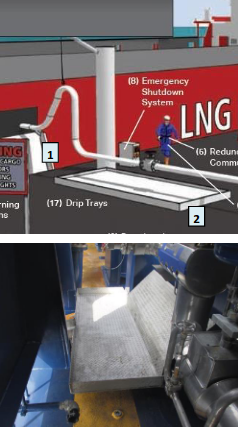
Drip trays are in fact, today, the most commonly used solution to contain LNG leakage and prevent damage to the ship’s structure, being featured in the IGF Code as an actual requirement for the bunkering station. This includes the location below any flanged connection, typically fitted with spray shields, in the LNG piping system or where leakage may occur.
Drip trays should be sized to contain the maximum amount of leakage expected and made from suitable material, such as stainless steel. Cryogenic pipes and equipment are typically thermally insulated from the ship’s structure to prevent the extreme cold from being transferred via conduction. These requirements are especially important at the bunker station because this is where LNG leaks or spills are most likely to occur.
General Good Practice by Port Authorities & Administrations
LNG as Fuel for Ports
R2.1. From a general perspective it is important that PAAs incorporate the perspective that LNG as fuel is today a developing option for ship operators willing to improve ship’s environmental performance, whilst maintaining a viable and profitable operation.
R2.2. PAAs should provide leadership and create and maintain administrative frameworks to facilitate the development of a safe and environmentally sound LNG bunkering projects and infrastructure, including mobile and fixed small-scale LNG bunkering and energy applications.
R2.3. Port Regulations should incorporate LNG bunkering, defining the relevant standards and minimum requirements to be met by Operators. All aspects related to the lifecycle of LNG bunkering activity should be clearly identified and defined, from initial proposal, permitting process, operation and emergency.
R2.4. It is important that PAAs define clearly the scope of responsibility for Operators when initiating and developing an LNG Bunkering Solution. In particular there should be clear requirements with regards to Quality Management system that includes LNG bunkering activities and objectives referring to relevant standards. (For the present Guidance the relevant standard for LNG bunkering Operation is EN ISO 20519 Specification for bunkering of liquefied natural gas fuelled vessels, with references, where relevant, to ISO/TS 18683 Guidelines for systems and installations for supply of LNG as fuel to ships.)
R2.5. With LNG bunkering being a relatively new port service, being added gradually to Port services portfolio, it is recommended that relevant instruments are developed to allow learning, experience and best practices to be shared amongst operators, with other ports and with other local stakeholders, directly or indirectly involved or affected by LNG bunkering.
R2.6. PAAs are advised to adopt an approach adequate to the different LNG bunkering lifecycle stage. Table 2.25,* below, includes the best practice advisable approach for PAAs when assessing, evaluating.
LNG Supply Chain
R2.7. The range of LNG bunkering options is today increasing as new technical solutions are brought to this specific market segment. More than rigid standardization in LNG bunkering it is important for PAAs to fully understand the supply chain proposed for a given LNG bunkering project, asking the initial questions:
- What is the LNG transport chain before arrival to Port under PAA jurisdiction/administration?
- How does the LNG arrive to Port (Truck/Vessel/Barge/Pipeline)?
- Is intermediate storage considered in the port? If so, is it a fixed permanent or temporary solution?
- Are the storage and bunkering location in the same place? If not, how far apart? How is LNG transported/routed to the bunkering location.
- Are there (re)-liquefaction facilities considered? If so, what is the production considered and associated storage?
- Will it be a single or multi-operator LNG bunkering chain?
- Is LNG truck loading also considered from on-site facilities?
- Which safety and environmental preliminary measures are being considered?
- How will Boil-Off Gas (BOG) be managed throughout the LNG chain in the Port? How will BOG be managed, in particular, during LNG bunkering/transfer to the receiving ship?
(Annex 1 includes a Template for the Initial Assessment of Concept LNG Bunkering Projects)
R2.8. The LNG supply chain should be made as simple as technically possible with the minimum number of interfaces and custody transfers as possible. This important goal should be instrumental in ensuring the necessary minimization of risks typically associated with LNG handling, transfer, purging, inerting and other typical LNG bunkering operations.
R2.9. The LNG bunkering supply chain should be streamlined, designed and operated so as to prevent any uncontrolled release into the environment. The main factors to be considered for the design of LNG supply chains are:
- Distance between intended LNG bunkering location and the LNG source (Import Terminal or production facility).
- LNG bunkering demand (low-high interval) – Volumes and Bunker flowrates estimated for the operation.
- Environmental, Land use planning and societal aspects in the port and surrounding the port area.
- Waterways suitability.
- Other services, involving handling of hazardous substances.
- Other LNG services – potential for synergies in the Port Area.
R2.10. The success of the LNG bunkering operation will, amongst other aspects, depend on the ability of the LNG supply chain to cope with LNG demand variations, whilst maintaining safety levels. It is therefore advisable to have into consideration the differences for a given LNG bunkering project and facility on both low and high demand scenarios.
LNG Bunkering operation – General aspects
R2.11. The Bunkering Facility Operator should implement a management system to develop, maintain and, where proven necessary, improve, the LNG Bunkering facilities and service. The safety and reliability of LNG Bunkering Facilities should be ensured through adequate design, construction, maintenance, inspection and monitoring and through sound management.
R2.12. The LNG bunkering operator (BFO) has primary responsibility throughout the whole lifecycle of its systems for ensuring safety and for taking measures to prevent accidents and limit their consequences for human health and the environment. Furthermore, in case of accidents, all possible measures should be taken to limit such consequences.
R2.13. Potential releases, resulting from hazardous accidental events, from any point of the LNG supply chain, in the vicinity and inside the port area, should be considered in the recognized adequately in a recognized and reliable way, especially in environmentally sensitive or highly populated areas.
R2.14. Deterministic and/or probabilistic approaches can be used in evaluating LNG bunkering facilities and operation, and assessing impacts on human health and the environment.
R2.15. Appropriate measures should be taken in case of accidents. Emergency plans should be established by pipeline operators (internal emergency plans) and by authorities (external emergency plans) and should be tested and regularly updated. These plans should include descriptions of the measures necessary to control accidents and limit their consequences for human health and the environment.
R2.16. Land-use planning considerations should be taken into account both in the development of LNG bunkering facilities (e. g. to limit proximity to populated areas and other port activities already established) and in decisions concerning proposals for new developments/construction in the vicinity of existing LNG bunkering facilities. These considerations are applicable to every element of the LNG supply chain, distribution, intermediate storage and bunkering/transfer.
R2.17. LNG Bunkering Operators and PAAs responsible for LNG bunkering facilities and location should review and, if necessary, develop and implement systems to reduce third-party interference, which is a main cause of accidents. This is, in particular, relevant for waterways access to LNG bunkering location, especially in higher nautical traffic areas.
R2.18. Information on the safety of LNG bunkering, the geographic position of LNG bunkering facilities, safety measures and the required behaviour in the event of an accident should be supplied to persons likely to be involved, directly or indirectly, in case of an LNG bunkering accident. General information should be made available to the public.
LNG Bunkering equipment
R2.19. LNG bunkering equipment, functional and technical requirements are outside the scope of the present Guidance. (Section “LNG Bunkering Equipment, Ships and Infrastructure”, on LNG Bunkering equipment is only of informative nature, providing typical characteristics for different elements of the LNG bunkering operational scenario, including typical performance of some of these elements, not only in terms of LNG bunkering typical storage volumes but also with some aspects of the technologies involved. The relevant Codes, Standards and other regulations should be consulted for reference.) PAAs should nevertheless be aware of the relevant applicable certification frame for each system and piece of equipment used in LNG bunkering. All equipment is required to be certified, following the provisions and technical requirements prescribed in the relevant applicable design codes and standards.
R2.20. PAAs should confirm regularly, following a specific inspection plan, if certificates are in place for the exact elements used in LNG bunkering. Section 15* in the present Guidance includes a list of indicative references that should be taken into account when confirming equipment certification.

- Study on the completion of an EU framework on LNG-fuelled ships and its relevant fuel provision infrastructure, LOT 1 Position paper: Towards harmonized EU LNG bunkering guidelines, DNV-GL, 2016.
- Study on the completion of an EU framework on LNG-fuelled ships and its relevant fuel provision infrastructure, LOT 1 Final Report, DNV-GL, 2016.
- LNG Bunkering Guidelines IACS Recommendation n. 142, on LNG Bunkering, IACS, 2016.
- ISO/TS 18683:2015. (15-Jan. 2015). Guidelines for systems and installations for supply of LNG as fuel to ships. Technical Specification.
- Society for Gas as a Marine Fuel (SGMF). (2015). Gas as a marine fuel, safety guidelines, Bunkering. Version 1.0, February 2015.
- ISO 20519:2017. Ships and marine technology – Specification for bunkering of gas fuelled ships. (International Standard).
- IEC 60079-10-1. (2015). Explosive atmospheres – Part 10-1: Classification of areas – Explosive gas atmospheres.
- Directive 1999/92/EC – ATEX of the European Parliament and of the Council of 16 December 1999 on minimum requirements for improving the safety and health protection of workers potentially at risk from explosive atmospheres (15th individual Directive within the meaning of Article 16(1) of Directive 89/391/EEC).
- API RP-500. 1997. Recommended practice for classification of locations for electrical installations at petroleum facilities classified as CIass 1, Division 1 and Division 2. Washington. D.C: API.
- API RP-505. 1997, Recommended practice for classification of locations at petroleum facilities classified as Class I, Zone 0, Zone 1 and Zone 2. Washington, D.C. API.
- NFPA 497. 2012, Recommended practice for the classification of flammable liquids, gases or vapours and of hazardous (classified) locations for electrical installations in chemical process areas. Quincy, MA: NFPA.
- IEC EN 60079-10-1 Ed.1.0, 2008. Electrical apparatus for explosive gas atmospheres – Part 10-1: Classification of areas – Explosive gas atmospheres. International Electrotechnical Commission.
- Commission Decision 2010/769/EU of 13 December 2010 on the establishment of criteria for the use by liquefied natural gas carriers of technological methods as an alternative to using low sulphur marine fuels meeting the requirements of Article 4b of Council Directive 1999/32/EC relating to a reduction in the sulphur content of certain liquid fuels as amended by Directive 2005/33/EC of the European Parliament and of the Council on the sulphur content of marine fuels (OJL 328, 14.12.2010, p. 15).
- USCG CG-OES Policy Letter 02-14 – Guidance Related To Vessels And Waterfront Facilities Conducting Liquefied Natural Gas (LNG) Marine Fuel Transfer (Bunkering) Operations.
- ADN – European Agreement concerning the International Carriage of Dangerous Goods by Inland waterways (Update version ADN January 2017).
- ADR – European agreement concerning the International Carriage of Dangerous Goods by Road (Update version ADR January 2017).
- Rhine Vessel Inspection Regulations (RVIR).
- EU general risk assessment methodology (Action 5 of Multi-Annual Action Plan for the surveillance of products in the EU (COM(2013)76) – Document 2015-IMP-MSG-15 – 16 October 2015.
- Safety Study, Chain analysis: Supplying Flemish ports with LNG as a marine fuel, Analysis of safety aspects, June 2012.
- EN 1160 – Installations And Equipment For Liquefied Natural Gas – General Characteristics Of Liquefied Natural Gas, NBN, 1st edition, August 1996.
- ESD Arrangements & Linked Ship/Shore Systems for Liquefied Gas Carriers, SIGTTO First Edition 2009 – SIGTTO.
- M. Kofod & S. Hartman, T. Mundt – Review of Recent Well-to-Wake Greenhouse Gas Studies evaluating the use of LNG as a marine Fuel, IMO MEPC/INF.15.
- LNG Access Code for Truck Loading for The Zeebrugge LNG Terminal – Based on version approved by the CREG on September 19th 2013 – Applicable as of January 1st 2014 – FLUXYS.
- Guidance for the Prevention of Rollover in LNG Ships – SIGTTO – First Edition 2012.
- Wang, Siyuan & Notteboom, Theo – The role of port authorities in the development of LNG bunkering facilities in North European ports, 14 January 2015, World Maritime University 2015.
- Verhoeven P (2010) A review of port authority functions: towards a renaissance? Marit Policy Manag 37:247-270.
- Society for Gas as a Marine Fuel (SGMF). (2017). Gas as a marine fuel, safety guidelines, Bunkering. Version 2.0, February 2015.
- COM(2003) 515 final – Communication from The Commission concerning the non-binding guide of good practice for implementing Directive 1999/92/EC of the European Parliament and of the Council on minimum requirements for improving the safety and health protection of workers potentially at risk from explosive atmospheres, Brussels, 25.8.2003.
- Davies, P. (2016) – Bunkering LNG: Setting the Safety Zone, 7th Motorship Gas Fuelled Ships Conference, November 2016.
- International Association of Oil & Gas Producers. (1-Mar 2010). Risk Assessment Data Directory – Process Release Frequencies. Report No. 434 – 1, 1 March 2010). Pertinent data from this report is summarised in: Davies & Fort, (Sept 2012), LNG as Marine Fuel – Likelihood of LNG Releases, Journal of Marine Engineering and Technology.
- PGS2 – TNO Yellow Book – Methods for the calculation of physical effects, due to releases of hazardous materials (liquids and gases) – CPR 14E (3rd Edition, 2005) – TNO – The Netherlands Organization of Applied Scientific Research.
- OECD Guiding Principles for Chemical Accident Prevention, Preparedness and Response, Guidance for Industry (including Management and Labour), Public Authorities, Communities, and other Stakeholders – 2nd Edition (2003) – OECD Environment, Health and Safety Publications.
- DNVGL-RP-G105 Edition October 2015 – Development and operation of liquefied natural gas bunkering facilities, Recommended Practice, DNV GL, 2015.
- USCG CG-OES Policy Letter No. 01-17 – Guidance for Evaluating Simultaneous Operations (SIMOPS) during Liquefied Natural Gas (LNG) Fuel Transfer Operations.
- LGC NCOE Field Notice 01-2017 – 14-Aug-17 – Recommended Process For Analysing Risk Of Simultaneous Operations (SIMOPS) During Liquefied Natural Gas (LNG) Bunkering.
- An Overview of Leading Software Tools for QRA, American Society of Safety Engineers – Middle East Chapter (161), 7th Professional Development Conference & Exhibition, March 18-22, 2005.
- Walter Chukwunonso Ikealumba and Hongwei Wu (2016) Some Recent Advances in Liquefied Natural Gas (LNG) Production, Spill, Dispersion, and Safety School of Chemical and Petroleum Engineering, Curtin University.