The burgeoning global demand for energy has cemented liquefied natural gas (LNG) as a pivotal fuel source, necessitating highly specialized infrastructure for its safe and efficient transport and storage. At the heart of this infrastructure lies the LNG containment system, a critical engineering marvel designed to safely house cryogenic LNG at incredibly low temperatures.
- IMO Type A Tank
- IMO Type B Tank
- IMO Type C Tank
- Membrane Tank
- LNG Trucks
- LNG Truck Common Bunkering Manifold
- ISO LNG Tanks
- Rigid/Mechanical arms
- LNG bunkering stations
- Liquefaction units
- LNG pipeline (fixed installations)
- LNG hoses
- General Good Practice by Port Authorities & Administrations
- LNG as Fuel for Ports
- LNG Supply Chain
- LNG Bunkering operation – General aspects
- LNG Bunkering equipment
These sophisticated systems are not merely tanks; they represent the culmination of advanced material science, complex thermodynamic principles, and rigorous safety protocols, ensuring the integrity and security of this vital energy commodity from production to consumption.
For the cargo tanks used on gas carriers, a distinction is generally made between non-self-supporting tanks (atmospheric membrane tanks) and self-supporting tanks (actual pressure tanks). The self-supporting cargo tanks are subdivided into three classes according to their strength. The same classification (IMO Classification) is used for LNG fuelled ships, to define the LNG fuel tanks.
IMO Type A Tank
These are prismatic cargo tanks with a low design pressure (< 0,7 barg). The material used in the construction of these tanks offers insufficient resistance to crack propagation, so that for safety reasons a second shell (tank wall) has to be provided to contain any leaks.
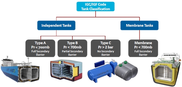
This second shell can also be formed by parts of the ship (e. g. inner hull) provided that these are capable of resisting the low temperature of the cargo.
IMO Type B Tank
These are prismatic or Shore Natural Gas Storage Tanksspherical cargo tanks with a low design pressure (< 0,7 barg), for which a great deal of attention has been paid in the design phase to detailed stress analyses (inter alia in relation to fatigue and crack propagation). Spherical Moss-Rosenberg tanks are the best known example of this type of tank.
Read also: Challenges Developing Natural Gas Infrastructure
Because of the improved design, a type B cargo tank only needs to have a partial second shell, fitted on the underside of the tank in the form of a drip tray.
IMO Type C Tank
These are spherical, cylindrical or bilobe pressure tanks with a design pressure greater than 2 barg. The tanks are designed and built according to the conventional pressure vessel codes and, as a result, can be subjected to accurate stress analyses. Moreover, in the design phase much attention is paid to eliminating possible stresses in the tank material. For these reasons, type C cargo tanks do not require a second shell.
For ships in which the cargo is transported in a cooled and partially pressurised state, the cargo tanks and associated apparatus are typically designed for a working pressure of 4 to 6 barg and a vacuum of 0,5 bar.
The Independent Cargo Tankscargo tanks are typically insulated with polystyrene or polyurethane panels attached to the tank wall.
Membrane Tank
The inner surface of the insulation is exposed to the cargo. – Membrane tank – Membrane tanks are not-self-supporting tanks which consist of a thin layer (membrane) supported through insulation by the adjacent hull structure.
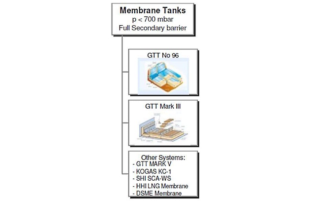
Despite the fact that membrane tanks are today widely used in LNG cargo tankers, the application of these technologies for LNG as Fuel is still without much expression.
Key Characteristics of Membrane Tanks SystemsMembrane tanks, as in Type A or B, optimize holding time by improved insulation.
LNG Trucks
Regional transport and local distribution of LNG can also be performed using LNG trucks provided that the distance between the loading and unloading locations is not too great (max. 500 km) and the consumption of the local consumer is small.
The capacity of LNG trucks varies from 35 to 56 m3 for conventional trucks and up to 80 m3 for a truck/trailer combination. As an alternative to trucks, ISO tank containers with a capacity of 21 m3 (20″ container) or 45 m3 (40″ container) can also be used.
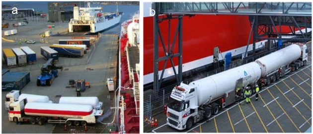
a – LNG truck bunkering with second truck-trailer for Nitrogen/Inert Gas supply; b – 2 (two) LNG trucks bunkering back-to-back via common 2-way manifold derivation.
In some countries there may be a restriction on the maximum authorised mass (MAM) Maximum authorised mass (MAM) means the weight of a vehicle or trailer including the maximum load that can be carried safely when it’s being used on the road. This is also known as gross vehicle weight (GVW) or permissible maximum weight. It will be listed in the owner’s manual and is normally shown on a plate or sticker fitted to the vehicle. The plate or sticker may also show a gross train weight (GTW), also sometimes called gross combination weight (GCW). This is the total weight of the tractor unit plus trailer plus load.x of trucks used for domestic transport.
In terms of cargo tank design, LNG trucks can be divided into two types:
- Trucks with a single-walled cargo tank made of stainless steel, insulated with insulating rigid polyurethane panels and fitted with a thin aluminium or stainless-steel protective cover The use of single-wall trucks for domestic transportation of LNG is not allowed in some countries due to concerns about the fire safety of these trucks given the flammable nature of the insulating material.x;
- Trucks with a double-walled vacuum-insulated cargo tank comprising an inner tank made of aluminium or stainless steel and an outer tank of carbon steel. The space between the inner and outer tanks is a vacuum and is further insulated with perlite, glass wool or a super-insulating foil.
The cargo tank of an LNG truck typically has a design pressure of 5 to 6 barg and is equipped with a redundant overpressure protection system with two safety valves.
The main specifications of LNG trucks are presented below. The pressure and temperature of the LNG in the truck during transportation is typically between 0 and 3 barg (-160 °C and -142 °C).
| Table 6. General specifications of LNG trucks | |
|---|---|
| Volume | 35 – 56 m3 (14 – 23 tonnes of LNG) |
| Maximum Filling % | Max. 90 % |
| Max. 90 % Design pressure (test pressure) | 5-6 barg (9 barg) |
| Set pressure of safety valves | typically 5-6 barg |
LNG trucks can be loaded at large LNG import terminals or medium sized bunker terminals at a rate of 50 – 100 m3/h. The LNG is pumped from the LNG storage tanks into the truck using a submersible pump via a fixed cryogenic pipe and a flexible (un)loading hose. The displaced LNG vapour is returned to the Cargo Storage System Concepts for Liquid Natural Gas Tanksstorage tanks via a vapour return line.
Unloading of LNG trucks at a bunker terminal or local bunkering station is also done using a flexible hose (2-3″) and a fixed cryogenic pipe at a typical rate of 40 to 60 m3/h. The LNG can be transferred using a pump fitted on the truck or by raising the pressure in the truck using a pressure build-up coil or a connection to an external nitrogen or natural gas network.
LNG Truck Common Bunkering Manifold
As LNG bunkering demand increases, the capacity of LNG truck (both in terms of volumes or LNG transfer rates) becomes insufficient. To continue using LNG trucks for TTS bunkering, the option found to increase volumes and transfer rates and optimize LNG bunker delivery operation times includes today common manifold structures as the one presented in the figure to the left.

The option for common manifolds has been first featured in IACS Rec. 142 where it is mentioned: Depending on the shore side arrangement it may be possible to increase the bunker rate to some extent by simultaneous bunkering from multiple trucks via a common manifold.
It will be interesting: Guide for Planning Gas Trials for LNG Vessels
Adequate and detailed operating procedures are important for safety of the operation. All the steps (preparation, pre-bunkering, bunkering, post-bunkering should be carefully detailed and explained. The risks and safety of the whole operation should be carefully assessed, not only in terms of Guidance on HAZID and HAZOP for LNG bunkering operationsHAZID and HAZOP analysis for the LNG bunkering operation, but also on the implications for the LNG bunkering location.
ISO LNG Tanks
ISO LNG Tanks are elements with the potential to play an important role in the LNG fuel value chain, not only as cargo but also as fuel.
With the following typical capacities:
- ISO 20 ft: 20,5 m3;
- ISO 40 ft: 43,5 m3.
With the possibility of portable fuel tanks to be used as LNG fuel units included in the IGF Code IGF Code Section.x, it is possible to consider the use of these elements as fuel storage for ships converted to LNG as fuel that did not make use of the hull internal volume to place fixed LNG fuel storage.

1 – 20ft ISO LNG and 2 – 40 ft ISO LNG; 3 – is the artistic representation of the LNG FuelPac ISO concept from Wartsila with ISO portable tanks, “plug-in” common manifold and evaporator on deck
A normal tank container intended for transporting LNG cannot, however, be used directly as a portable fuel tank since it does not fulfil all the requirements for marine LNG fuel tanks. Modifications relating to remote monitoring and The Global Maritime Distress and Safety System – Principles & Practicesafety systems, IMO type C tank requirements, and leakage & spill protection are a few items that need to be specifically considered for marine fuel tanks.
The list below identifies the characteristics of LNG portable fuel tanks that need to be considered, on top of those required for LNG cargo ISO tanks.
- Standart ISO frame;
- Compliance with transportation regulations (IMDG, TRED, ADR, RID, CSC among others):
- Only the first two requirements are required for ISO LNG tanks. Remaining aspects to be covered for LNG portable tanks.
- Compliance with rules for use as LNG fuel tank on board ships:
- IMO Type-C tank;
- Water spraying system;
- Tank safety relief valves designed for fire case;
- Connection to external vent mast;
- LNG leakedg detection and protection;
- Class approvesd equpment & design;
- Stainless steel outer shell;
- Dry disconnect quick couplings;
- Connections at end for connecting to ship;
- Connection to automation system on the ship;
- Connection to safety systems on the ship.
Rigid/Mechanical arms
Whilst smaller diameter 2 to 3″ LNG hoses are easily handled by hand, larger diameters are far more difficult to handle. The use of dedicated, or general purpose, cranes have therefore been of great assistance in the operation of LNG hoses for connection with the LNG receiving vessel.
In addition to the support of LNG hoses weight during bunkering, other aspects are important drivers for the use of mechanical rigid LNG bunkering arms:
- Safety of the whole LNG bunkering operation;
- Precision in the connect/disconnect procedure;
- Optimization of bunkering duration;
- Possibility to deliver LNG bunker connection at different heights.
Full rigid arms are provided with rigid insulated pipe sections through which LNG is pumped through to the receiving vessel. Swivel joints allow the necessary motion in the intended degrees of movement, whilst pneumatic/hydraulic assisted mechanisms provide the motion and binary forces for the mechanic arm.
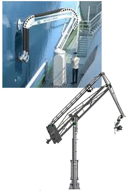
1 – Mechanical arm for hose handling with dedicated saddle articulated points and; 2 – Example of a full articulated mechanical LNG bunker arm
Typical installations for such arms would be LNG bunkering fixed stations or LNG bunker vessels.
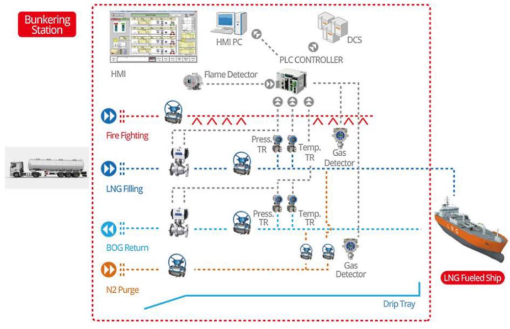
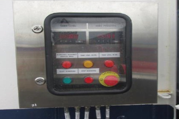
LNG bunkering stations
Local jetties can be equipped with a small-scale LNG bunkering station that is used to supply specific end users (e. g. service vessels or ferries).
The storage capacity of such bunkering stations is typically 100 to 3 500 m3. Bunkering takes place by means of a fixed bunkering installation (i. e. a cryogenic pipe and loading arm or flexible hose) from the stationary LNG storage tanks at a rate of 50 – 500 m3/h depending on the size of the vessel being supplied.
Such stations are generally supplied by small LNG ships (capacity: 500 to 3 000 m3) or LNG trucks that bring the LNG from a nearby LNG bunker terminal or from a large LNG import terminal. A possible alternative to supplying LNG by ship or truck is to build a small-scale liquefaction unit with a capacity of 5 000 to 20 000 tpa in the immediate vicinity of the station.
The figure to the left show some examples of small-scale LNG stations.
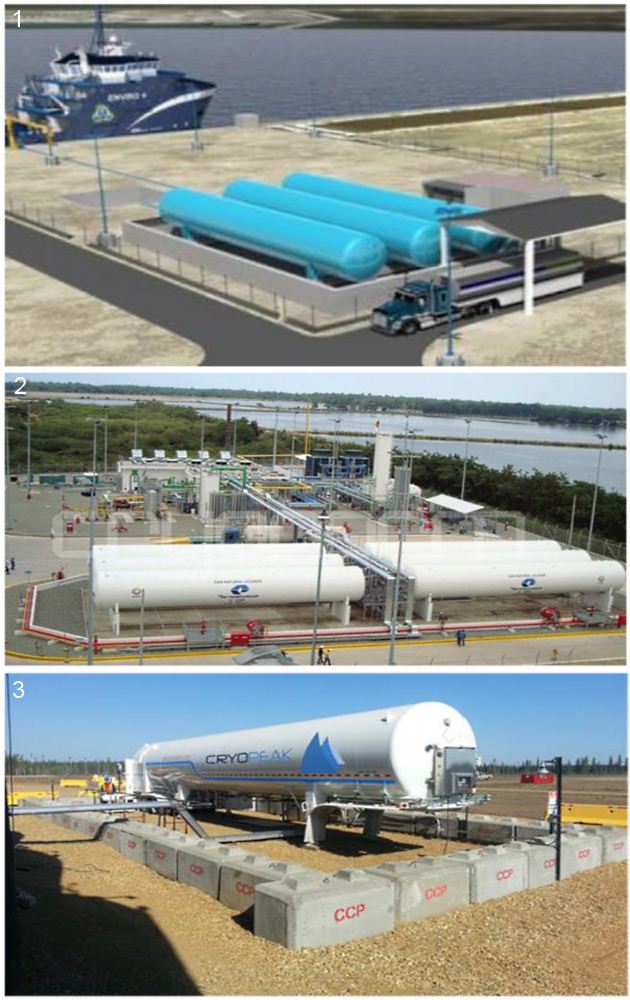
Whereas the two figures on the top are demonstrative of small-scale fixed LNG bunkering stations, the one on the bottom is intended to demonstrate what can be achieved through a temporary installation of an LNG trailer, on a semi-fixed installation. It is important that PAAs are aware that even if this situation is not a fixed installation, similar concerns should be considered. The use of LNG trailer trucks in semi-fixed LNG bunkering installations should not represent a way to avoid more stringent regulatory requirements for fixed small scale LNG bunkering sites.
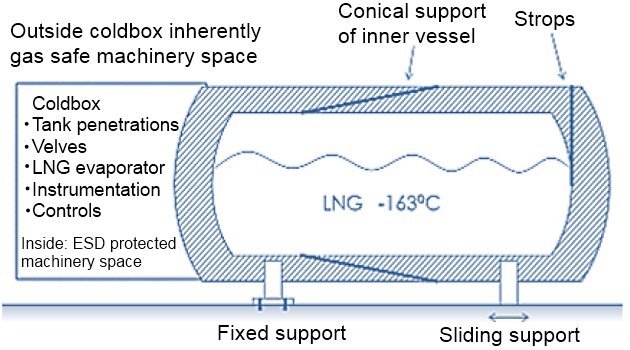
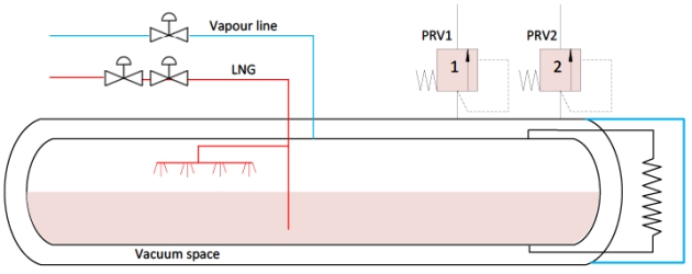
The storage tanks used at a local LNG bunkering station are typically cylindrical tanks with a volume of 100 to 1 000 m3. More specifically, they are double-walled vacuum insulated pressure tanks set up either horizontally or vertically. The degree of filling of the tanks must not exceed 95 % under any circumstances, in line with ADR requirements.
Read also: Key Systems for LNG Carriers Containment and Safety: Design and Operation
The LNG is stored in the tanks at a pressure of 0 to 4 barg and a temperature of -160 °C to -138 °C. Because the tanks are vacuum-stribution system has the ability to managinsulated, little heat is lost through the tank wall and the tank pressure will only rise very gradually during long periods when no LNG is withdrawn. The tanks are also fitted with an ambient air vaporiser to keep the tank pressure at the desired level as well as a redundant overpressure protection system with two safety valves.
The figure below shows a schematic representation of a vacuum-insulated LNG tank.
The characteristics dimensions of such tanks are given in the table below:
| Table 7. Typical characteristic dimensions for LNG storage pressure tanks | ||||
|---|---|---|---|---|
| Tank Volume | 100 m3 | 250 m3 | 500 m3 | 700 m3 |
| Diameter | 6,5 | 4,3 | 5 | 5,5 |
| Length | 16,5 | 23 | 30 | 35 |
| Max. connection (mm), [inches] | (100) [4] | (150) [6] | (150) [6] | (200) [8] |
The Ship to Ship Bunkering Operations of the Liquefied Natural Gasship bunkering installation is similar to the installation used to unload LNG ships, namely a fixed cryogenic pipe and a flexible hose or loading arm. The flow rates applied when bunkering vessels using a fixed installation are typically 50 to 500 m3/h depending on the size of the ship being supplied.
Fixed LNG bunkering stations can be loaded both from ships or trucks:
Loading from LNG ships: LNG ships unloaded at a bunkering station have a typical capacity of 500 to 3 000 m3 and unloading takes place via a fixed arm or a flexible hose at a rate of 200 – 1 000 m3/h. The diameter of the unloading arm or hose used for this purpose is 4″ to 8″. The LNG is transferred to the storage tank via a cryogenic unloading pipe with a diameter of 4″ or 10″. The unloading pipes must be kept as short as possible (< 250 m) to minimise boil-off gas losses and associated pressure increase in the LNG line.
Loading from LNG ships: The LNG trucks used to supply the station are generally unloaded at a rate of 40 – 60 m3/h using a flexible unloading hose (3″) and a cryogenic LNG pipe (3″/4″). The LNG can be transferred using a pump fitted on the truck or by raising the pressure in the truck using a pressure build-up coil.
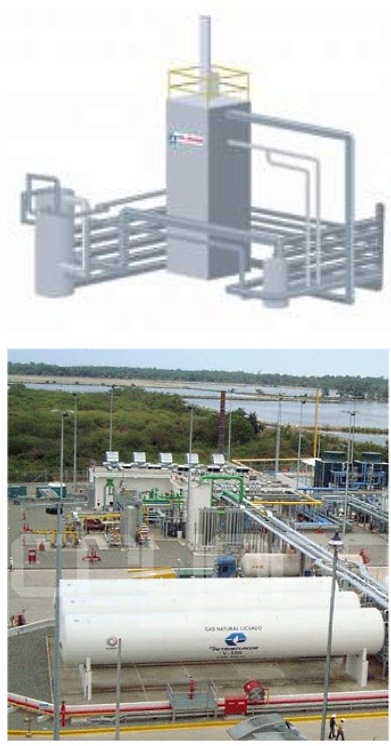
Liquefaction units
Building a small to medium-sized liquefaction unit is a possible alternative to shipping in LNG to bunker terminals and bunkering stations. Such liquefaction units have a production capacity of 5 000 to 20 000 tpa (for bunkering stations) and 40 000 to 300 000 tpa (for bunker terminals).
Medium-sized liquefaction units typically have a production capacity of 270 to 2 000 m3 of LNG per day, which implies a natural gas consumption of 7 200 to 54 000 m3(n)/h.
Small liquefaction units typically have a production capacity of 35 to 135 m3 of LNG per day, which implies a
For LNG liquefaction units with a capacity of 5 000 – 300 000 tpa, the following process cycles are mainly used:
- an open cycle with turboexpander;
- a closed one- or two-stage cycle with nitrogen refrigerant;
- a closed one- or two-stage cycle with mixed refrigerant.
LNG (re)-liquefaction plants are important infrastructure elements that allow both production of LNG onsite and Boil-Off Gas management through re-liquefaction.
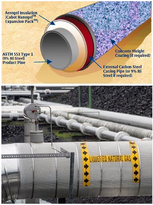
LNG pipeline (fixed installations)
Pipelines in Marine Terminals: Key Considerations for Handling Liquefied GasLNG pipelines are increasingly important elements in the context of LNG bunkering. They allow the LNG fuel to be transferred from the storage location (pressure or atmospheric tanks) into the LNG bunkering location.
Even though they are not very common for The total length of the pipelines is limited to the efficiency of the insulation and, in principle, should not be longer than 250 m. This will depend on many aspects which are mostly local-dependent and whether the LNG distribution system has the ability to manage BOG generated during transfer.
The LNG pipeline layout design can consider different routing solutions, either by aerial route with supports or lay along a special trench, designed to keep the LNG pipeline offset from the risks associated to vehicle circulation hazards/accidents.
LNG pipelines are then able to feed either local numbering manifolds or directly into mechanical articulated arms as the one presented in this table, above.
Whenever LNG pipelines are routed, aerial, over ground or underground, crossing public domain spaces, careful consideration must be paid to Safety with special dedicated measures and barriers to mitigate the risk of hazardous events affecting the pipeline.
Inerting arrangements to be part of the LNG bunkering station. LNG pipeline to be permanently inerted outside LNG bunkering operation.
LNG hoses
LNG bunkering hoses are important elements in the LNG bunkering operation. Typically in composite multi-layer thermoplastic, LNG hoses are to be designed and certified according to the following standards:
- EN 1474-2 – Design and testing of marine transfer systems. Design and testing of transfer hoses;
- EN 13766:2010 – Thermoplastic multi-layer (non-vulcanized) hoses and hose assemblies for the transfer of liquid petroleum gas and liquefied natural gas – Specification.
Typically, the bunker hose is expected to be provided by the supplier. It should be suitably long and flexible, such that the hose can remain connected to both the supplier’s manifold and the receiving ship’s manifold during normal relative movements expected from wind, waves, draft changes, current, and surges from passing vessels. Typically, bunker hoses are constructed of composite materials and are flexible to allow for relative movements. The supplier should provide a bunker connection at the hose end that will match the receiving ship’s connection. Although industry standardization has not yet been implemented, ISO/TS 18683:2015 references relevant standards.
It will be interesting: Other Characteristics Specific to Liquefied Gas Tankers
Additionally, the hose should be capable of releasing without damage or significant spills if the relative position or movement of the receiving ship exceeds the limits. LNG bunker hoses are typically fitted with connections that are of the quick connect type and remain sealed until the connection (drip-free type) is made. The receiver’s end of the hose also will usually be fitted with an emergency release system (ERS), such as a drip-free, breakaway coupling that gives way before excessive pull causes the hose to break or other damage to occur.
This type of coupling uses spring loaded shutoff valves to seal the break and stop any LNG or vapour release. Quick connect and break-away couplings are readily available in the market and minimize the possibility of LNG leakage and gas escape.

1 – Bunkering of the MV Viking Grace with bunker hose handled from the bunker vessel side; 2 – LNG bunkering hose suspended from crane line, noting the attention to the hose suspension point where pressure is distributed along the saddle curvature
Cranes, loose gear, supports, etc., are to be provided for hose handling and Basic Information about Liquefied Natural Gas Bunkering Operationsbunkering operations and are to be designed, arranged and surveyed in accordance with the applicable requirements of the ABS Guide for Certification of Lifting Appliances.
iii) Hose supports or cradles are to be used where necessary to keep hose bends within the design limits, as per manufacturer’s recommendations.
iv) Fixed LNG bunker transfer systems are to be designed and tested in accordance with recognized standards such as EN1474-3 (offshore transfer system) and/or EN1474-2 (transfer hoses). LNG bunker transfer systems and hoses are to be arranged to provide sufficient flexibility over the range of expected relative vessel motions.

Hoses can also be part of hybrid flexible/rigid/mechanical systems, such as the one presented to the left. ERC and connector to be also fitted at the end.
Emergency Release System (ERS)
The present Guidance refers to ERS, ERC and ESD in the terms presented in EN ISO 20519, where ERS is defined as a system comprised of two sub-systems/elements that allow the main functional requirement of quick/dry disconnect during bunkering operation, as a consequence of an emergency.
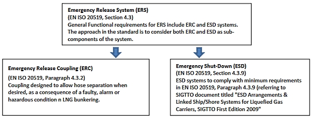
Emergency Shut-Down (ESD)
An emergency shut-down (ESD) is a method or a system that safely and effectively stops the transfer of LNG (and vapour as applicable) between the LNG bunkering facility and the receiving ship in the event of an emergency during the bunkering operation. The control systems involved in the ESD, which is a linked system to allow both parties (on board receiving ship and the bunkering facility) to shut down the transfer in an emergency situation, can be activated automatically or manually.
The ESD may consist of two parts:
- ESD-stage 1, is a system that shuts the LNG transfer process down in a controlled manner when it receives inputs from one or more of the following; transfer personnel, high levels LNG tank alarms, cables or other means designed to detect excessive movement between transfer vessels or vessel and an LNG port facility, or other alarms.
- ESD-stage 2, is a system that activates decoupling of the transfer system between the transfer vessels or between a vessel and an LNG port facility. The decoupling mechanism contains quick acting valves designed to contain the contents of the LNG transfer line (dry break) during decoupling.
Typical reasons for activation of the ESD include the following:
- Gas detection;
- Fire detection;
- Manual activation from either the supplier or receiver;
- Excessive ship movement;
- Power failure;
- High level in receiving tank;
- Abnormal pressure in transfer system;
- High tank pressure;
- Excessive stress in LNG bunker arm.
Other causes as determined by system designers and regulatory organizations.
ESD systems to comply with minimum requirements in EN ISO 20519, Paragraph 4.3.9 (referring to SIGTTO document titled “ESD Arrangements & Linked Ship/Shore Systems for Liquefied Gas Carriers, SIGTTO First Edition 2009″.
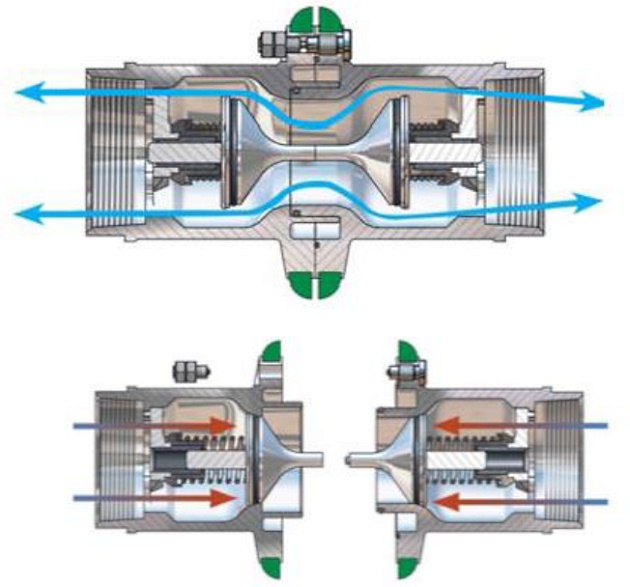
Emergency Release Coupling (ERC)
A breakaway coupling or emergency release coupling (ERC) is a coupling located in the LNG transfer system (at one end of the transfer system, either the receiving ship end or the bunker facility end, or in the middle of the transfer system), which separates at a predetermined section when required, each separated section containing a self-closing shut-off valve, which seals automatically.
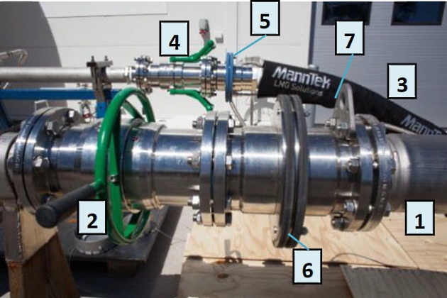
1 -LNG bunkering line; 2 – Main Quick-Connect/Dry Disconnect coupling (QC/DC); 3 – Vapour return line; 4 – Return QC/DC; 5 – ERC main line; 6 – ERC Vapour Return; 7 – Pad-eye for LNG bunkering hose crane handling
ESD systems to comply with minimum requirements in EN ISO 20519, Paragraph 4.3.9 (referring to SIGTTO document titled “ESD Arrangements & Linked Ship/Shore Systems for Liquefied Gas Carriers, SIGTTO First Edition 2009″.
Dry Quick-Connect/ Disconnect Coupling
Dry Quick Connect/Disconnect couplings (Dry QC/DC) are a specific type of couplings that allow easy connection/disconnection without the use of manual intensive operation (such as tightening bolts), whilst including self-containing stop valves at the female and male ends to avoid spillage of hose and receiving line LNG content that may possibly be contained in the lines (if not inerted).
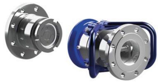
The coupling consists of a Nozzle (male) and a receptacle (female). The nozzle allows quick connection and disconnection of the fuel supply hose to the receptacle, mounted on the LNG manifold. Connectors used shall be designed to operate as quick connect/disconnect couplings. Couplings, in nominal sizes up to 6″, for flows up to 650 m3/h, and maximum flow rates of 10 m/s.
The advantages of standard quick connectors are as follows:
- avoid mix-up and use of any connector designed for other fluids or gasses through the safety of a unique standard geometry;
- allow for a quick and easy mechanical solution with efficient and safe connection specially designed for cryogenic LNG;
- avoid company standards that will normally be protected by property rights and may be limited to contracts and brand distributors, which normally results in less competition and hamper public procurement;
- prevent the safety risk of fitting additional adaptors and gaskets to convert between different company standards and the risk of using parts not adequate for cryogenic fluids;
- avoid the temptation to make or modify adaptors, to fix something on short notice, with possible limited access to the right material and manufacturing equipment;
- eliminate the need for manual bolting and manual re-tightening after down-cooling to cryogenic temperatures;
- avoid leaks (methane slip) and problems due to uneven tightening and any accident if wrong studs accidentally have been used;
- avoid torsion problems as the connectors have swivel features and thus torsion problems that may arise on flanges do not exist; and
- ensure conformant operation and safety training for all personnel involved in bunkering on a world-wide basis.
ESD systems to comply with minimum functional requirements in EN ISO 20519, Paragraph 4.3.
- Ensure compliance of the couplings with the Functional Requirements in EN ISO 20519.
- Consult with Classification Society on the best options to optimize LNG bunkering compatibility with receiving vessel.
- Liaise with Industry Association (such as SGMF) or other in order to get the best.
Vessels transferring or receiving low flashpoint flammable liquids, such as LNG, need to take additional precautions against ignition resulting from electrical arcing.
Two causes of arcing are:
- Static electricity build-up in the LNG bunker hose;
- Differences in potential between the ship and bunker supplier’s facility, including the quay or pier, trucks, bunker vessels, etc.
Based on empirical data, the use of electrical interconnecting cables in LNG bunkering operations is not recommended.
An effective way of preventing arcing is to isolate the ship and the bunker supplier using an isolating (insulating) flange fitted at one end of the bunker hose only, in addition to an electrically continuous bunker hose.
Read also: The International Trade LNG and LPG
The isolating flange, an example of which is shown in Figure 17, prevents arcs from passing between the ship and facility even if there is a difference in potential. Furthermore, because the hose is electrically continuous and one end is grounded to either the ship or the bunker supplier, static electricity will effectively be dissipated.
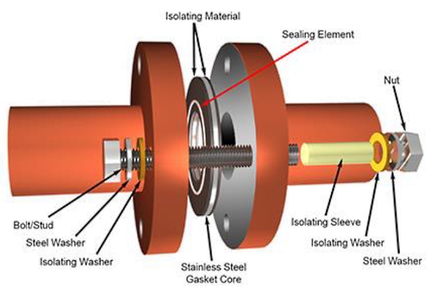
An alternative method is to use one short section of insulating hose without any isolating flanges, but with the rest of the bunker hose string electrically continuous. To ensure that the ship is completely isolated from the supplier, it may be necessary to isolate mooring lines, gangways, cranes, and any other physical connections. This is typically done by using rope tails on mooring lines, insulating rubber feet on the end of gangways, and prohibiting the use of certain equipment that would otherwise pose an unacceptable risk of arcing.
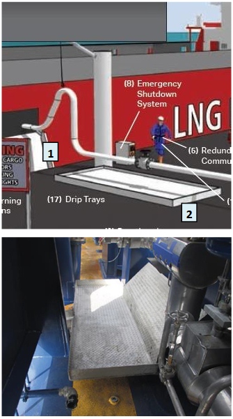
Drip Trays
To avoid LNG spillages in contact with decks or other exposed parts of the ship structure, from becoming structural failure hazardous events (with cryogenic cracking associated to carbon-steel embrittlement) two possible solutions may be possible:
- Design for local cryogenic resistant structure;
- Use of stainless steel drip trays.
Drip trays are in fact, today, the most commonly used solution to contain LNG leakage and prevent damage to the ship’s structure, being featured in the IGF Code as an actual requirement for the bunkering station. This includes the location below any flanged connection, typically fitted with spray shields, in the LNG piping system or where leakage may occur.
General Good Practice by Port Authorities & Administrations
LNG as Fuel for Ports
From a general perspective it is important that PAAs incorporate the perspective that LNG as fuel is today a developing option for ship operators willing to improve ship’s environmental performance, whilst maintaining a viable and profitable operation.
PAAs should provide leadership and create and maintain administrative frameworks to facilitate the development of a safe and environmentally sound LNG bunkering projects and infrastructure, including mobile and fixed small-scale LNG bunkering and energy applications.
Port Regulations should incorporate LNG bunkering, defining the relevant standards and minimum requirements to be met by Operators. All aspects related to the lifecycle of LNG bunkering activity should be clearly identified and defined, from initial proposal, permitting process, operation and emergency.
It is important that PAAs define clearly the scope of responsibility for Operators when initiating and developing an LNG Bunkering Solution. In particular there should be clear requirements with regards to Quality Management system that includes LNG bunkering activities and objectives referring to relevant standards For the present Guidance the relevant standard for LNG bunkering Operation is EN ISO 20519 Specification for bunkering of liquefied natural gas fuelled vessels, with references, where relevant, to ISO/TS 18683 Guidelines for systems and installations for supply of LNG as fuel to ships.x.
With LNG bunkering being a relatively new port service, being added gradually to Port services portfolio, it is recommended that relevant instruments are developed to allow learning, experience and best practices to be shared amongst operators, with other ports and with other local stakeholders, directly or indirectly involved or affected by LNG bunkering.
PAAs are advised to adopt an approach adequate to the different LNG bunkering lifecycle stage.
LNG Supply Chain
The range of LNG bunkering options is today increasing as new technical solutions are brought to this specific market segment. More than rigid standardization in LNG bunkering it is important for PAAs to fully understand the supply chain proposed for a given LNG bunkering project, asking the initial questions:
a. What is the LNG transport chain before arrival to Port under PAA jurisdiction/ administration?
b. How does the LNG arrive to Port (Truck/Vessel/Barge/Pipeline)?
c. Is intermediate storage considered in the port? If so, is it a fixed permanent or temporary solution?
d. Are the storage and bunkering location in the same place? If not, how far apart? How is LNG transported/routed to the bunkering location.
e. Are there (re)-liquefaction facilities considered? If so, what is the production considered and associated storage?
f. Will it be a single or multi-operator LNG bunkering chain?
g. Is LNG truck loading also considered from on-site facilities?
h. Which safety and environmental preliminary measures are being considered?
i. How will Boil-Off Gas (BOG) be managed throughout the LNG chain in the Port? How will BOG be managed, in particular, during LNG bunkering/transfer to the receiving ship?
The LNG supply chain should be made as simple as technically possible with the minimum number of interfaces and custody transfers as possible. This important goal should be instrumental in ensuring the necessary minimization of risks typically associated with LNG handling, transfer, purging, inerting and other typical LNG bunkering operations.
- Indicate port(s) for which the study is intended.
- Characterize the climate and terrain characteristics of the port.
- To define the operational profile of the specific port(s) activities.
- Comment on the available multi-modal links converging in the port.
- Characterize the LNG operations intended for the specified port and, if operations and infrastructure already developed, to provide indication of the existing LNG plant characteristics in the port, both in capacity and operational profile.
LNG bunkering supply chain should be streamlined, designed and operated so as to prevent any uncontrolled release into the environment. The main factors to be considered for the design of LNG supply chains are:
a. Distance between intended LNG bunkering location and the LNG source (Import Terminal or production facility).
b. LNG bunkering demand (low-high interval) – Volumes and Bunker flowrates estimated for the operation.
c. Environmental, Land use planning and societal aspects in the port and surrounding the port area.
d. Waterways suitability.
e. Other services, involving handling of hazardous substances.
f. Other LNG services – potential for synergies in the Port Area.
The success of the LNG bunkering operation will, amongst other aspects, depend on the ability of the LNG supply chain to cope with LNG demand variations, whilst maintaining safety levels. It is therefore advisable to have into consideration the differences for a given LNG bunkering project and facility on both low and high demand scenarios.
LNG Bunkering operation – General aspects
The Bunkering Facility Operator should implement a management system to develop, maintain and, where proven necessary, improve, the LNG Bunkering facilities and service. The safety and reliability of LNG Bunkering Facilities should be ensured through adequate design, construction, maintenance, inspection and monitoring and through sound management.
The LNG bunkering operator (BFO) has primary responsibility throughout the whole lifecycle of its systems for ensuring safety and for taking measures to prevent accidents and limit their consequences for human health and the environment. Furthermore, in case of accidents, all possible measures should be taken to limit such consequences.
Potential releases, resulting from hazardous accidental events, from any point of the LNG supply chain, in the vicinity and inside the port area, should be considered in the recognized adequately in a recognized and reliable way, especially in environmentally sensitive or highly populated areas.
Deterministic and/or probabilistic approaches can be used in evaluating LNG bunkering facilities and operation, and assessing impacts on human health and the environment.
Read also: Cargo Tank Instrumentation on Gas Tankers
Appropriate measures should be taken in case of accidents. Emergency plans should be established by pipeline operators (internal emergency plans) and by authorities (external emergency plans) and should be tested and regularly updated. These plans should include descriptions of the measures necessary to control accidents and limit their consequences for human health and the environment.
Land-use planning considerations should be taken into account both in the development of LNG bunkering facilities (e. g. to limit proximity to populated areas and other port activities already established) and in decisions concerning proposals for new developments/construction in the vicinity of existing LNG bunkering facilities. These considerations are applicable to every element of the LNG supply chain, distribution, intermediate storage and bunkering/transfer.
LNG Bunkering Operators and PAAs responsible for LNG bunkering facilities and location should review and, if necessary, develop and implement systems to reduce third-party interference, which is a main cause of accidents. This is, in particular, relevant for waterways access to LNG bunkering location, especially in higher nautical traffic areas.
Information on the safety of LNG bunkering, the geographic position of LNG bunkering facilities, safety measures and the required behaviour in the event of an accident should be supplied to persons likely to be involved, directly or indirectly, in case of an LNG bunkering accident. General information should be made available to the public.
LNG Bunkering equipment
LNG bunkering equipment, functional and technical requirements are outside the scope of the present Guidance. PAAs should nevertheless be aware of the relevant applicable certification frame for each system and piece of equipment used in LNG bunkering. All equipment is required to be certified, following the provisions and technical requirements prescribed in the relevant applicable design codes and standards.
PAAs should confirm regularly, following a specific inspection plan, if certificates are in place for the exact elements used in LNG bunkering. Article Guide to Certification, Accreditation, and Equipment Standards for LNG Bunkering“Certification & Accreditation” in the present Guidance includes a list of indicative references that should be taken into account when confirming equipment certification.

- Study on the completion of an EU framework on LNG-fuelled ships and its relevant fuel provision infrastructure, LOT 1 Position paper: Towards harmonized EU LNG bunkering guidelines, DNV-GL, 2016.
- Study on the completion of an EU framework on LNG-fuelled ships and its relevant fuel provision infrastructure, LOT 1 Final Report, DNV-GL, 2016.
- LNG Bunkering Guidelines IACS Recommendation n. 142, on LNG Bunkering, IACS, 2016.
- ISO/TS 18683:2015. (15-Jan. 2015). Guidelines for systems and installations for supply of LNG as fuel to ships. Technical Specification.
- Society for Gas as a Marine Fuel (SGMF). (2015). Gas as a marine fuel, safety guidelines, Bunkering. Version 1.0, February 2015.
- ISO 20519:2017. Ships and marine technology – Specification for bunkering of gas fuelled ships. (International Standard).
- IEC 60079-10-1. (2015). Explosive atmospheres – Part 10-1: Classification of areas – Explosive gas atmospheres.
- Directive 1999/92/EC – ATEX of the European Parliament and of the Council of 16 December 1999 on minimum requirements for improving the safety and health protection of workers potentially at risk from explosive atmospheres (15th individual Directive within the meaning of Article 16(1) of Directive 89/391/EEC)
- API RP-500. 1997. Recommended practice for classification of locations for electrical installations at petroleum facilities classified as CIass 1, Division 1 and Division 2. Washington. D.C: API.
- API RP-505. 1997, Recommended practice for classification of locations at petroleum facilities classified as Class I, Zone 0, Zone 1 and Zone 2. Washington, D.C. API.
- NFPA 497. 2012, Recommended practice for the classification of flammable liquids, gases or vapours and of hazardous (classified) locations for electrical installations in chemical process areas. Quincy, MA: NFPA.
- IEC EN 60079-10-1 Ed.1.0, 2008. Electrical apparatus for explosive gas atmospheres – Part 10-1: Classification of areas – Explosive gas atmospheres. International Electrotechnical Commission.
- Commission Decision 2010/769/EU of 13 December 2010 on the establishment of criteria for the use by liquefied natural gas carriers of technological methods as an alternative to using low sulphur marine fuels meeting the requirements of Article 4b of Council Directive 1999/32/EC relating to a reduction in the sulphur content of certain liquid fuels as amended by Directive 2005/33/EC of the European Parliament and of the Council on the sulphur content of marine fuels (OJ L 328, 14.12.2010, p. 15).
- USCG CG-OES Policy Letter 02-14 – Guidance Related To Vessels And Waterfront Facilities Conducting Liquefied Natural Gas (LNG) Marine Fuel Transfer (Bunkering) Operations.
- ADN – European Agreement concerning the International Carriage of Dangerous Goods by Inland waterways (Update version ADN January 2017).
- ADR – European agreement concerning the International Carriage of Dangerous Goods by Road (Update version ADR January 2017).
- Rhine Vessel Inspection Regulations (RVIR).
- EU general risk assessment methodology (Action 5 of Multi-Annual Action Plan for the surveillance of products in the EU (COM(2013)76) – Document 2015-IMP-MSG-15 – 16 October 2015.
- Safety Study, Chain analysis: Supplying Flemish ports with LNG as a marine fuel, Analysis of safety aspects, June 2012.
- EN 1160 – Installations And Equipment For Liquefied Natural Gas – General Characteristics Of Liquefied Natural Gas, NBN, 1st edition, August 1996.
- ESD Arrangements & Linked Ship/Shore Systems for Liquefied Gas Carriers, SIGTTO First Edition 2009 – SIGTTO.
- M. Kofod & S. Hartman, T. Mundt – Review of Recent Well-to-Wake Greenhouse Gas Studies evaluating the use of LNG as a marine Fuel, IMO MEPC/INF.15.
- LNG Access Code for Truck Loading for The Zeebrugge LNG Terminal – Based on version approved by the CREG on September 19th 2013 – Applicable as of January 1st 2014 – FLUXYS.
- Guidance for the Prevention of Rollover in LNG Ships – SIGTTO – First Edition 2012.
- Wang, Siyuan & Notteboom, Theo – The role of port authorities in the development of LNG bunkering facilities in North European ports, 14 January 2015, World Maritime University 2015.
- Verhoeven P (2010) A review of port authority functions: towards a renaissance? Marit Policy Manag 37:247-270.
- Society for Gas as a Marine Fuel (SGMF). (2017). Gas as a marine fuel, safety guidelines, Bunkering. Version 2.0, February 2015.
- COM(2003) 515 final – Communication from The Commission concerning the non-binding guide of good practice for implementing Directive 1999/92/EC of the European Parliament and of the Council on minimum requirements for improving the safety and health protection of workers potentially at risk from explosive atmospheres, Brussels, 25.8.2003.
- Davies, P. (2016) – Bunkering LNG: Setting the Safety Zone, 7th Motorship Gas Fuelled Ships Conference, November 2016.
- International Association of Oil & Gas Producers. (1-Mar 2010). Risk Assessment Data Directory – Process Release Frequencies. Report No. 434 – 1, 1 March 2010). Pertinent data from this report is summarised in: Davies & Fort, (Sept 2012), LNG as Marine Fuel – Likelihood of LNG Releases, Journal of Marine Engineering and Technology.
- PGS2 – TNO Yellow Book – Methods for the calculation of physical effects, due to releases of hazardous materials (liquids and gases) – CPR 14E (3rd Edition, 2005) – TNO – The Netherlands Organization of Applied Scientific Research.
- OECD Guiding Principles for Chemical Accident Prevention, Preparedness and Response, Guidance for Industry (including Management and Labour), Public Authorities, Communities, and other Stakeholders – 2nd Edition (2003) – OECD Environment, Health and Safety Publications.
- DNVGL-RP-G105 Edition October 2015 – Development and operation of liquefied natural gas bunkering facilities, Recommended Practice, DNV GL, 2015.
- USCG CG-OES Policy Letter No. 01-17 – Guidance for Evaluating Simultaneous Operations (SIMOPS) during Liquefied Natural Gas (LNG) Fuel Transfer Operations.
- LGC NCOE Field Notice 01-2017 – 14-Aug-17 – Recommended Process For Analysing Risk Of Simultaneous Operations (SIMOPS) During Liquefied Natural Gas (LNG) Bunkering.
- An Overview of Leading Software Tools for QRA, American Society of Safety Engineers – Middle East Chapter (161), 7th Professional Development Conference & Exhibition, March 18-22, 2005.
- Walter Chukwunonso Ikealumba and Hongwei Wu (2016) Some Recent Advances in Liquefied Natural Gas (LNG) Production, Spill, Dispersion, and Safety School of Chemical and Petroleum Engineering, Curtin University.