The maritime industry is undergoing a significant transformation driven by the urgent need to reduce emissions and embrace cleaner fuels. Among the most promising alternatives, Liquefied Natural Gas (LNG) has emerged as a frontrunner, offering substantial environmental benefits compared to traditional marine fuels. However, unlocking the full potential of LNG as a marine fuel hinges critically on the development of robust and efficient LNG Bunkering Infrastructure.
This article will delve into the multifaceted world of LNG bunkering, exploring its definition, various supply and operational modes, and the essential equipment, ships, and infrastructure that underpin this evolving ecosystem. Understanding these key components is crucial for stakeholders navigating the transition towards a more sustainable shipping future.
LNG Bunkering
Definition
Regulation 2017/352 provides the more general definition, used in the context of this Guidance. Adapting that definition for the case of LNG bunkering the following definition is provided:
LNG Bunkering is in fact a particular type of operation where LNG fuel is transferred from a given distribution source to a LNG fuelled ship. It involves the participation of different stakeholders, from the ship-side, LNG supplier, ports, safety personnel, administrations and policy makers. In addition to the supply of the LNG fuel itself, also the operation of supplying LNG sourced energy to the waterborne vessel, whilst at berth, is included in the present Guidance document.
LNG Bunkering Supply Mode
One of the main challenges with Guidance on HAZID and HAZOP for LNG bunkering operationsLNG Bunkering is the interfaces created during LNG delivery moment. These challenges can be either of a regulatory or technical nature, but not only. In fact, on top of particular standards and technological needs for LNG as a marine fuel to be bunkered safely, it is important to acknowledge the relevance of harmonization. The creation of interface environments in LNG bunkering raises the concern about how different regulatory frames (“land side” vs “ship side“, “road” vs “port“, “road” vs “ship-side“, etc.). Ideally regulations and requirements should tend towards harmonization and non-conflicting regimes, but this is not always the case. On top of this the interface can also unveil potential training discrepancies, equipment mismatches and other factors that can, ultimately, influence Safety and affect the Environment with unnecessary methane emissions. The minimization of risk to life and property, and the mitigation of gas release are the fundamental drivers to make the LNG chain inside the port area as lean and simple as technically possible.
From a PAA perspective in the definition of an LNG Bunkering concept the main elements that are considered for the present questionnaire are:
a) How the LNG arrives to the port are?
b) Whether it is intermediately stored within the port?
c) and How is the LNG delivered to the receiving vessel?
Different options are possible by the combination of replies to these questions. Table 1, below, includes a combination of different supply elements.
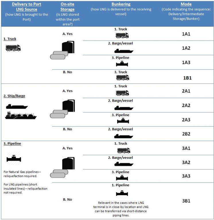
Many different combinations are possible. With these different combinations there are different regulatory instruments; at national, regional or international level which also concur (these are explored in article “Regulatory Framework”). The identification of potential conflicting requirements will also be relevant for the outlining of guidelines that may be able to resolve them, clarifying, streamlining and identifying possibly adjusted procedures.
Read also: LNG Transportation Risks and Essential Insights
Also featured in the present Guidance the Special Modes presented in table 2 where, in fact, no transfer of fuel occurs in the interface (in S4 the transfer is of a containerized unit and in S5 or S6 the transfer is not of the LNG fuel but of LNG-sourced electricity). The definition used for LNG bunkering in the context of this Guidance allows these options to be also considered.
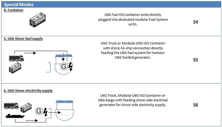
Table 2 above shows the options for LNG fuel supply in the port area Scale of LNG developments and facilities“Guidance Map”.
The concept followed is here that of the presence of LNG as a hazardous substance in the vicinity of the receiving LNG vessel. Whether the transfer operation occurs in the interface or not is only important for the detailed technical guidance. At the level of Risk & Safety and concept of operations the presence of LNG in the proximity of the LNG fuel receiving vessel.
Having codified the LNG supply options in the previous tables it is now further detailed how these options can influence the concept of operations inside the Port, which aspects can be challenging from PAAs perspective and, also, how these can possibly influence the Spatial Planning of the Port as an important responsibility of PAAs when accommodating for LNG bunkering in the port services portfolio.
| Table 3. LNG fuel supply options inside the Port area Scale of LNG developments and facilities“Guidance Map” | |||
|---|---|---|---|
| LNG Supply Mode (Code from Tables 2 and 3) | Description | Observations/ Conditioning Factors | |
| 1A1 | 1 | LNG is brought to the Port area by truck. | Number of trucks to keep storage capacity can be significant, depending on the demand. |
| 2 | Storage in pressurized or atmospheric tanks, inside the port. | Relevant if Port Area is large and LNG between storage and Receiving Ship is not viable by pipeline. | |
| 3 | LNG is then loaded for TTS bunkering on a spot demand basis. Final movement of LNG inside the port by wheels. | Reduced LNG bunkering capacity (each truck will be able to deliver approximately 25ton of LNG (in slightly less than an hour) – see section “LNG Bunkering Equipment, Ships and Infrastructure” for more detailed information. | |
| 4 | Bunkering by Truck-to-Ship from the storage and loading site. | Any potential variation-increase in bunkering demand would lead to an increase in the number of truck movements in the port area, both loading-on and loading-off. | |
| 5 | Intermediate storage facilities used as buffer spot between supply of LNG and bunkering demand. | ||
| Nr. of LNG transfers inside the port: 3. | |||
| 1A2 | 1 | LNG is brought to the Port area by truck. | Loading-on by trucks and loading-off by vessel is a very unlikely option accounting for the inflow/outflow balance. With very different capacities between truck LNG trailers and waterborne LNG transport (50 m3 against 500 to 5 000 m3, respectively) |
| 2 | Storage in pressurized or atmospheric tanks, inside the port. | ||
| 3 | LNG is then loaded for STS bunkering. Final movement of LNG inside the port area by ship/barge. | ||
| 4 | Bunkering by Ship-to-Ship from the storage and loading site. | ||
| Nr. of LNG transfers inside the port: 3. | |||
| 1A3 | 1 | LNG is brought to the Port area by truck. | Loading of onsite storage facilities by truck is a very limited option to bring LNG fuel into the port area. |
| 2 | Storage in pressurized or atmospheric tanks, inside the port. | For higher demands in LNG volumes it will represent a rather intense LNG tuck traffic into the port area with a consequently high rate of loading operations. | |
| 3 | LNG is then transferred to the bunkering facility by pipeline onto a manifold, rigid arm or bunkering hose. | Limited pipeline length by need to reduce pressure increase in the line due to heat influx along the transfer pipeline (even if insulated). | |
| Nr. of LNG transfers inside the port: 2. | |||
| 1B1 | 1 | Truck-to-Ship (TTS) directly to ship. LNG is brought to the Port in the same truck that will bunker the receiving vessel. | This is perhaps the most common method for LNG bunkering today, despite the very limited capacity and LNG bunkering rates available from TTS solutions (around 50-200 m3 and 40-60 m3/h). |
| 2 | No fixed storage of LNG. | Despite the low capacity and bunker rates this is an option that allows flexibility and response to spot-demand. | |
| Nr. of LNG transfers inside the port: 1. | |||
| 2A1 | 1 | LNG comes to the port by ship/barge, typically an LNG feeder vessel of higher capacity serving the intermediate logistical link between larger LNG import terminals and smaller LNG bunker facilities. | This represents an option that would allow high capacity and loading rates onto an intermediate storage tank within the Port, breaking this into smaller volumes for loading LNG trucks (or even multi-costumer hub), adding value to the port in terms of multi-service portfolio. |
| 2 | LNG is loaded from the intermediate storage tanks onto LNG trucks for bunkering at designated location(s) inside the port. | Different LNG Bunkering operator can be involved if multi-operator loading from the storage site is allowed. | |
| Nr. of LNG transfers inside the port: 3. | Different designated LNG bunkering locations could be served allowing for flexible LNG bunkering response. | ||
| 2A2 | 1 | LNG comes to the port by ship/barge, typically an LNG feeder vessel of higher capacity serving the intermediate logistical link between larger LNG import terminals and smaller LNG bunker facilities. | This represents an option that would allow high capacity and loading rates onto an intermediate storage tank within the Port. |
| 2 | LNG is loaded from the intermediate storage tanks onto smaller LNG bunker barges for bunkering at designated location(s) inside the port. | Different LNG Bunkering operator can be involved if multi-operator loading from the storage site is allowed. | |
| Nr. of LNG transfers inside the port: 1. | Different designated LNG bunkering locations could be served allowing for flexible LNG bunkering response. | ||
| 2A3 | 1 | LNG comes to the port by ship/barge, typically an LNG feeder vessel of higher capacity serving the intermediate logistical link between larger LNG import terminals and smaller LNG bunker facilities. | This is an inflexible method because the bunkering location must be close to the LNG storage tank(s) (≤ 250 m). Also, there may be conflicts with other activities taking place on the quay (i. e. loading/unloading of ships). |
| 2 | LNG is transferred from storage tank location to bunkering facility by pipeline, either underground or above ground supports. | It is mainly indicated for situations with high bunker frequencies and small bunker volumes (e. g. supplying service vessels or scheduled ferry services). | |
| Nr. of LNG transfers inside the port: 2. | |||
| 2B2 | 1 | LNG comes to the port area in the LNG bunker vessel/barge directly to bunker a waterborne receiving vessel, either at anchor or at berth. | This method is mainly used for large bunker volumes (100 to 20 000 m3) and high bunker frequencies, with the bunker vessel being supplied from a large import terminal or medium-sized bunker terminal. Bunkering can take place at the quay where the ship is berthed or at a specific anchorage in port or out at sea. The capacity of the bunker vessel and the bunkering rate applied must be tailored to the fuel needs of the ships being supplied. |
| 2 | No intermediate storage in the port area. | This is a flexible method with which high bunkering rates can be achieved. The downsides are the high costs (initial investment and use) and possible interference with through traffic in the port. | |
| It is important that careful nautical analysis is made for the LNG bunkering location. | |||
| Nr. of LNG transfers inside the port: 1. | For some ships bunkering by the outside may represent significant operational advantages, allowing the quay side for other possible operations. | ||
| 3A1 | 1 | LNG can be derived from pipeline into the Port area in 2 different ways: | This represents an option that would allow high capacity and loading rates onto an intermediate storage tank within the Port, breaking this into smaller volumes for loading LNG trucks (or even multi-costumer hub), adding value to the port in terms of multi-service portfolio. |
| a | Natural Gas pipeline into re-liquefaction unit inside the port area. | Different LNG Bunkering operator can be involved if multi-operator loading from the storage site is allowed. | |
| b | LNG pipeline from outside the Port area, from close-by LNG Import Terminal outside the port. | Different designated LNG bunkering locations could be served allowing for flexible LNG bunkering response. | |
| 2 | LNG stored in intermediate onsite pressure/atmospheric tanks within the port area. | ||
| 3 | LNG loaded into LNG trailer trucks, for later bunkering at designated bunkering location. | ||
| Nr. of LNG transfers inside the port: 2. | |||
| 3A2 | 1 | LNG can be derived from pipeline into the Port area in 2 different ways: | LNG bunkering via bunker vessel/barge is a solution for high capacity and high transfer rates. |
| a | Natural Gas pipeline into re- liquefaction unit inside the port area. | Having a re-liquefaction facility onsite would allow flexibility in the production of LNG that would potentially be favourable to adjust the offer to the demand in peak demand periods. | |
| b | LNG pipeline from outside the Port area, from close-by LNG Import Terminal outside the port. | This represents an option that would allow high capacity and loading rates onto an intermediate storage tank within the Port, breaking this into smaller volumes for loading LNG trucks (or even multi-costumer hub), adding value to the port in terms of multi-service portfolio. | |
| 2 | LNG stored in intermediate onsite pressure/atmospheric tanks within the port area. | ||
| 3 | LNG loaded into LNG bunker vessel/barge, for later bunkering at designated bunkering location. | ||
| Nr. of LNG transfers inside the port: 2. | |||
| 3A3 | 1 | LNG can be derived from pipeline into the Port area in 2 different ways: | This is an inflexible method because the bunkering location must be close to the LNG storage tank(s) (≤ 250 m). Also, there may be conflicts with other activities taking place on the quay (i. e. loading/unloading of ships). |
| a | Natural Gas pipeline into re-liquefaction unit inside the port area. | The layout of de LNG pipeline will have an impact on spatial planning, dictating important local construction measures. | |
| b | LNG pipeline from outside the Port area, from close-by LNG Import Terminal outside the port. | Typical solution indicated for high bunkering rates and volumes. | |
| 2 | LNG stored in intermediate onsite pressure/atmospheric tanks within the port area. | ||
| 3 | Transfer for bunkering location by LNG pipeline (short distance run). | ||
| Nr. of LNG transfers inside the port: 1. | |||
| 3B1 | 1 | In the case featured there is no intermediate onsite storage. LNG would come to the port area in liquid form, via special insulated pipeline. | This is an inflexible method because not only the bunkering location must be close to the LNG storage tank(s) (≤ 250 m). |
| Bringing LNG into the port area by special insulated line would also mean that the LNG production would have to be very close to the port, representing several challenges in spatial planning. | |||
| Nr. of LNG transfers inside the port: 1. | Should the LNG be sourced from another ship or barge berthed at a different quay, the challenges would be similar, in particular with the layout for the special pipelines. | ||
| S4 | 1 | LNG fuel is here transferred to the receiving waterborne vessel via portable tanks. | The present Guidance includes bunkering by portable tanks within its scope. This is not the same approach followed in all LNG bunkering references where LNG fuel portable tanks are dealt as hazardous materials handling operations. In the context of the definition presented in section “Definition” of the present Guidance this is considered bunkering. Important note to make is that there is no correct way of classifying this, but aligning requirements for loading in and rolling in portable LNG containers should be in line with IGF Code requirements for these tanks onboard. Since the IGF Code deals with fuel, and not cargo, the operation of loading or rolling LNG fuel tanks, followed by their safe stowage and connection is here featured as an LNG bunkering option.x |
| 2 | LNG portable tanks can be embarked loaded-in or rolled-in, if transferred in suspension by crane or embarked directly via truck, respectively. | It will be important for the port to differentiate the handling of these containerized units from other containerized cargo. | |
| The differentiation mentioned above should encompass: | |||
| I. Bunkering location. | |||
| II. Possible intermediate storage location for LNG portable tanks (safe area in the quay side). | |||
| Nr. of LNG transfers inside the port: 0 (LNG transfer occurs inside the ship). | III. Possible limitations in the loading/rolling in operation accounting for other operations. | ||
| S5 | 1 | LNG can be supplied to an LNG fuelled waterborne vessel whilst at berth, directly from an LNG trailer tank, ISO portable container or even barge to an LNG fuel burning unit onboard. | This operation is mentioned throughout the Guidance as “LNG fuelling” but, in fact, it consists of a bunkering operation scoped within the definition presented in section “Definition”. |
| 2 | The LNG would, in this case, be fed through an Evaporator onboard onto the gas fuelled unit (engine, boiler…) at the exact consumption rate of that unit. | The challenges presented to this type of operation are similar to the LNG fuel transfer operation, with the additional concern that the LNG storage stands outside, close to the vessel in a location that is, otherwise, not a fuel storage location. | |
| 3 | The LNG truck, portable tank or barges are used in this option as LNG temporary storage unit for the receiving ship whilst at berth. | The interesting aspect of this option is that ships can improve their environmental performance whilst at berth without having to invest in onboard LNG storage or complex fuel systems. | |
| The challenge is that, whilst LNG fuel storage spaces onboard are regulated by the IGF Code, it is not the same case outside the ship and, therefore, also outside the scope of the IGF Code. | |||
| S6 | 1 | In this case, electrical energy is supplied to the receiving vessel, not LNG. | This operation is by far the one the most different from typical LNG bunkering operation and, in fact, LNG is never transferred to the receiving vessel. |
| 2 | LNG fuel is used by power generation units, or small-scale power plants, that will provide electrical shore-side energy to the receiving vessel. | The most relevant aspect to take into account, this special situation S6 is the fact that a small LNG power plant is close to the receiving vessel, either alongside or in the vicinity of the receiving vessel. | |
| It represents an important application of LNG energy, adding value to the Ports environmental performance and, also, allowing ships to meet air emissions requirements whilst at birth. | |||
LNG Bunkering Modes
Delivering LNG (Liquefied Natural Gas) as FuelLNG fuel to a ship can be done in different ways, following different methods, depending on different logistic and operational factors. Various LNG bunkering methods are available, with Truck-to-Ship (TTS) being the most commonly used.
Today’s choice for TTS method has been a result of different aspects and difficulties that concur in the development of the business case for bunkering LNG as a marine fuel. On one hand the operational flexibility and limited infrastructure requirements for TTS and, on the other hand, relatively low initial investment to establish business readiness, have driven the option for this Functional and General Requirements for LNG Bunkering OperationLNG bunkering method. The table below covers the relevant possible methods of bunkering LNG fuelled vessels.
| Table 4. LNG bunkering methods | |||||
|---|---|---|---|---|---|
| Method | Typical Volumes (V) and Bunker Rates (Q) | Advantages | Disadvantages | ||
| Truck-to-Ship – TTS | LNG truck connected to the receiving ship on the quayside, using a flexible hose, assisted typically by a hose-handling manual cantilever crane. |  | V ≈ 50-100 m3 | Operational Flexibility. | Limited capacity of trucks: approximately 40-80 m3 is likely to dictate multi-truck operation. |
| Limited Infrastructure requirements. | Limited flow-rates (900 – 1 200 l/hr) | ||||
| Q ≈ 40 – 60 m3/h | Possibility to adjust delivered volumes (nr. of trucks) to different client needs. | Significant impact on other operations involving passengers and/or cargo. | |||
| Possibility to adapt to different safety requirements. | Limited movement on the quay-side, mostly influenced by the presence of the bunker truck(s). | ||||
| Possibility to serve different LNG fuel users on point-to- point delivery. | Exposure to roadside eventual limitations (permitting, physical limitations, traffic related, etc.) | ||||
| Ship-to-Ship – STS | LNG is delivered to the receiving vessels by another ship, boat or barge, moored alongside on the opposite side to the quay. LNG delivery hose is handled by the bunker. |  | V ≈ 100 – 6 500 m3 | Generally does not interfere with cargo/passenger handling operations. Simultaneous Operations (SIMOPS) concept is favoured. | Initial investment costs involving design, procurement, construction and operation of an LNG fuelled vessel/barge. |
| Q ≈ 500 – 1 000 m3/h | Most favourable option for LNG bunkering, especially for ships with a short port turnaround time. | Significant impact in life-cycle cost figures for the specific LNG bunker business. | |||
| Larger delivery capacity and higher rates than TTS method. | Limited size for bunker vessel, conditioned by port limitations. | ||||
| Operational flexibility – bunkering can take place alongside, with receiving vessel moored, at anchor or at station. | |||||
| Terminal (Port)-to-Ship – PTS | LNG is either bunkered directly from a small storage unit (LNG tank) of LNG fuel, small station, or from an import or export terminal. |  | V ≈ 500 – 20 000 m3 | Possibility to deliver larger LNG volumes, at higher rates. | From operational perspective it may be difficult to get the LNG fuelled receiving vessel to the Terminal. |
| Q ≈ 1 000 – 2 000 m3/h | Good option for ports with stable, long-term bunkering demand. | Proximity of larger LNG terminal may not be easy to guarantee. | |||
| Calculation of available LNG for delivery, in small storage tanks, can be difficult unless pre-established contract exist. | |||||
| ISO Container-to-Ship | LNG can also be delivered to the receiving vessel by embarkation of ISO containerized LNG tanks. If the receiving vessel is pre-fitted with LNG connections the fuel can then be used. | 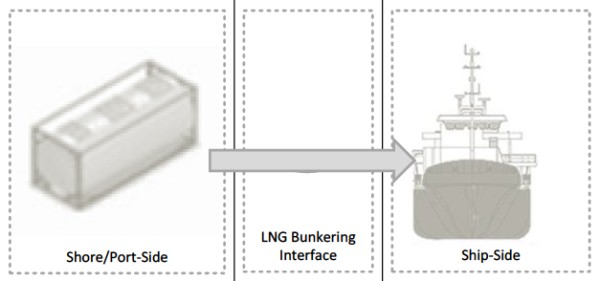 | Typical capacity: | Absence of interface bunkering operations. | Connections onboard need to comply with strict construction regulations. |
| ISO 20 ft: 20,5 m3 | Simplification by exempting operations from hoses and other operational aspects. | Limited volumes available in 20-40 m3 containers. | |||
| ISO 40 ft: 43,5 m3 | Potential advantages from intermodal possibilities. | Only suitable for a limited type of ships. | |||
| Leveraging of intermodal transportation. | Requires pre-installation of LNG fuel installation. | ||||
Depending on the LNG quantity needed and potential time constraints for the operation it is possible that different LNG bunkering modes are more applicable to different needs, from different ship types, operational profiles and LNG fuel Liquefied Gas Carrier Typesonboard storage capacities. Very likely larger ships, that potentially make use of LNG for longer voyages, will naturally require larger bunker volumes and, inevitably higher bunker rates. This is very likely the potential LNG bunkering characteristics for Very Large Container Ships, who stay at berth for the shortest time interval possible whilst potentially requiring the largest volumes of LNG bunkering. A suitable LNG bunkering method should therefore be provided for such needs. In addition to the capacity challenge.
| Table 5. Typical LNG bunkering per different generic ship type | |||||
|---|---|---|---|---|---|
| Vessel Type (Receiving vessel) | Bunker Quantity | Rate | Duration | Hoses or arm diameter (pol) | Adequate Bunkering Mode |
| Service vessels, tugboats, patrol boats and fishing boats | 50 m3 | 60 m3/h | 45 min | 2 × 2″ or 1 × 3″ | TTS |
| Small Ro-Ro and Ro-Pax vessels | 400 m3 | 400 m3/h | 1 hr | 2 × 4″ or 1 × 6″ | TTS/STS |
| Large Ro-Ro and Ro-Pax vessels | 800 m3 | 400 m3/h | 2 hr | 2 × 4″ or 1 × 6″ | STS |
| Small cargo, container and freight vessels | 2 000 – 3 000 m3 | 1 000 m3/h | 2 to 3 hr | 2 × 8″ or 1 × 12″ | STS |
| Large freight vessels | 4 000 m3 | 1 000 m3/h | 4 hr | 2 × 8″ or 1 × 12″ | STS |
| Large tankers, bulk carriers and container ships | 10 000 m3 | 2 500 m3/h | 4 hr | 2 × 10″ | STS/PTS |
| Very large container ships and oil tankers | 20 000 m3 | 3 000 m3/h | 7 hr | 2 × 12″ | STS/PTS |
All LNG bunkering modes share several fundamental aspects of concern that need to be carefully addressed in order to have safe and successful operations:
- Risk Analysis and Safety Management, intrinsically different depending on the method chosen for bunkering.
- Permitting, which will be needed for the different operations, from the relevant competent authorities.
- Training of all personnel involved, both onboard and ashore.
LNG Bunkering Equipment, Ships and Infrastructure
As identified in the previous sections, LNG bunkering can assume very different shapes in terms of LNG supply chain and LNG bunkering mode. This will relate to the particular aspects of bunkering location, receiving LNG vessel characteristics and BFO service portfolio. Inherent to the different bunkering options and modes it is possible to consider different equipment, ships and infrastructure elements that compose the different LNG bunkering solutions. Section below, includes these relevant elements with an indicative description for information.
LNG feeder vessels are small to medium-sized LNG carriers used for regional transport of LNG with a view to its use as ship fuel or the industrial use of Challenges Developing Natural Gas Infrastructurenatural gas in remote places.
LNG Feeder Vessels
LNG feeder vessels currently in operation or under construction are double-hulled gas carriers with a capacity of 7 500 – 30 000 m3. The size and main dimensions of the vessels will depend on market demand and the physical limitations of the intended unloading location, such as dimensions of the berthing site and draught at the jetty.
The figures below show some examples of LNG feeder vessels with different capacities.
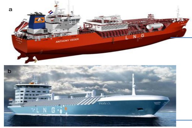
a – LNG Feeder vessels – “Coral Methane” (7 500 m3); b – “FKLAB L2” project (16 500 m3)
LNG feeder vessels can be loaded at large LNG import terminals. Loading takes place via fixed cryogenic pipes and flexible hoses or fixed arms at the typical rate of 1 000 – 6 000 m3/h (depending on the size of the feeder vessel). The LNG vapour displaced from the ship’s cargo tanks is returned to the terminal via a vapour return line.
It will be interesting: Guidelines for Automatic Cargo Tank Overfill Protection Aboard Gas Carriers
Unloading of the vessel at a bunker terminal or bunkering station is also done using fixed cryogenic pipes and flexible hoses or fixed arms. The LNG is pumped to the terminal by the submersible pumps fitted in the ship’s cargo tanks at a typical rate of 1 000 – 6 000 m3/h.
LNG Bunker Vessel
LNG bunker vessels are small LNG ships used for the direct supply of LNG fuel to ships inside or outside a port. During bunkering, the LNG is pumped from the bunker General Overview of LNG Cargo Tanks (Typical Operations)vessel’s cargo tanks directly into the fuel tanks of the ship being supplied. LNG bunker vessels are identical in design to LNG feeder vessels and typically have a capacity of 500 – 20 000 m3.
LNG bunker vessels represent today a key role in the ability of LNG bunkering to grow in capacity whilst avoiding the difficulties of shore side/quay operation. Bunkering from the opposite side to the quay will allow to design bunkering an port operation in a more flexible.
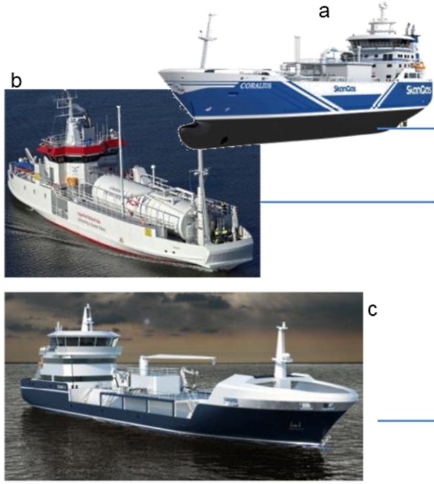
a – LNG bunker vessels – “Coralius” (5 800 m3); b – AGA “Seagas” (187 m3); c – “FKLAB L2” project (16 500 m3)
Small LNG bunker vessels (500 – 3 000 m3) are usually equipped with one or two cargo tanks. These are mainly A Study on Support Arrangement of a Cargo Tank for Tank Type-A Liquefied Petroleum Ships
cylindrical cargo tanks with a design pressure of 3 to 4 barg (IMO type C tank) and an individual tank capacity of 500 – 2 000 m3 of LNG.
LNG bunker vessels can be loaded at small to medium-sized bunker terminals or large LNG import terminals. Loading takes place via fixed cryogenic pipes and flexible hoses or fixed loading arms at a rate of 200 – 3 000 m3/h (depending on the size of the bunker vessel).
Bunkering is done using flexible hoses or fixed arms at a rate of 60 – 3 000 m3/h depending on the size of the fuel tanks on the receiving vessel.
Rules applicable to LNG bunker vessels are typically IGC Code unless the bunker vessel is operating only in inland waterways, outside the scope of IMO IGC Code applicability. Here the applicable instruments would be defined at National Administration level. In the EU context the ADN agreement, Directive 2016/1629 or RVIR regulation would apply.
Details of certification elements required for barges included in article Guide to Certification, Accreditation, and Equipment Standards for LNG Bunkering“Certification & Accreditation” of the present Guidance.
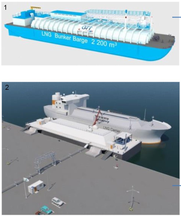
LNG Bunker Barge
LNG Bunker Barges are, essentially, the non-propelled version of LNG bunker vessels. All types of different LNG capacities and containment systems are possible, with a growing number of designs being developed.
Mobility of these barges is subject to push-pull tug arrangements or to any other external propelling unit that deliver the barge the ability to be moved around the port area, responding to different LNG bunkering needs in potential different LNG Ship to Ship Bunkering Operations of the Liquefied Natural Gasbunkering locations.
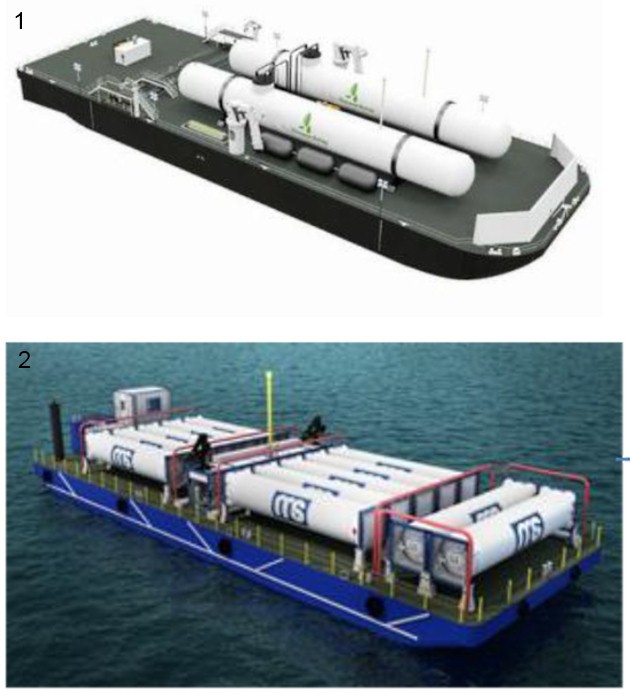
1 – barge with 2 (two) type-C tanks above deck; 2 – Transport barge with ISO 40’ LNG containers
The use of a tug or external unit for mobility represents, on one hand, a clear flexible option that allows moving different floating units with one propelling craft. On the other hand, it may represent a challenge for manoeuvrability in higher traffic waterways.
Read also: LNG System Features and Controls
Barges can have integral LNG tanks or, as in the cases presented in the figures to the left, tanks above main deck.
Whilst rules have been developed for LNG bunker vessels, mostly derived from IGC and IGF Codes, barges seem not to have a dedicated of of rules that apply directly to the carriage LNG fuel and bunkering services In general, barges intended for the carriage of liquefied gases in bulk are to comply with the International Code for the Construction and Equipment of Ships Carrying Liquefied Gases in Bulk (IGC Code) as appropriate, or other national standard, as applicable to the non-propelled status of the vessel. A special certificate attesting to the degree of compliance with the above codes or national standard may be issued upon request. For manned barges, consideration is to be given for full compliance with the code. In all cases, it is the Owner’s responsibility to determine the requirements of flag Administration and port Administration.x. This may impose a challenge in the harmonization of these floating craft that should be taken into consideration by PAAs.
1 – LNG bunker barge with membrane tank, equipped with rigid LNG transfer arm and; 2 – LNG Bunker barge, here seen as a berthing interface, similar to a floating storage unit (FSU) for LNG bunkering service
Details of certification elements required for barges included in article “Certification & Accreditation” of the present Guidance.

- Study on the completion of an EU framework on LNG-fuelled ships and its relevant fuel provision infrastructure, LOT 1 Position paper: Towards harmonized EU LNG bunkering guidelines, DNV-GL, 2016.
- Study on the completion of an EU framework on LNG-fuelled ships and its relevant fuel provision infrastructure, LOT 1 Final Report, DNV-GL, 2016.
- LNG Bunkering Guidelines IACS Recommendation n. 142, on LNG Bunkering, IACS, 2016.
- ISO/TS 18683:2015. (15-Jan. 2015). Guidelines for systems and installations for supply of LNG as fuel to ships. Technical Specification.
- Society for Gas as a Marine Fuel (SGMF). (2015). Gas as a marine fuel, safety guidelines, Bunkering. Version 1.0, February 2015.
- ISO 20519:2017. Ships and marine technology – Specification for bunkering of gas fuelled ships. (International Standard).
- IEC 60079-10-1. (2015). Explosive atmospheres – Part 10-1: Classification of areas – Explosive gas atmospheres.
- Directive 1999/92/EC – ATEX of the European Parliament and of the Council of 16 December 1999 on minimum requirements for improving the safety and health protection of workers potentially at risk from explosive atmospheres (15th individual Directive within the meaning of Article 16(1) of Directive 89/391/EEC)
- API RP-500. 1997. Recommended practice for classification of locations for electrical installations at petroleum facilities classified as CIass 1, Division 1 and Division 2. Washington. D.C: API.
- API RP-505. 1997, Recommended practice for classification of locations at petroleum facilities classified as Class I, Zone 0, Zone 1 and Zone 2. Washington, D.C. API.
- NFPA 497. 2012, Recommended practice for the classification of flammable liquids, gases or vapours and of hazardous (classified) locations for electrical installations in chemical process areas. Quincy, MA: NFPA.
- IEC EN 60079-10-1 Ed.1.0, 2008. Electrical apparatus for explosive gas atmospheres – Part 10-1: Classification of areas – Explosive gas atmospheres. International Electrotechnical Commission.
- Commission Decision 2010/769/EU of 13 December 2010 on the establishment of criteria for the use by liquefied natural gas carriers of technological methods as an alternative to using low sulphur marine fuels meeting the requirements of Article 4b of Council Directive 1999/32/EC relating to a reduction in the sulphur content of certain liquid fuels as amended by Directive 2005/33/EC of the European Parliament and of the Council on the sulphur content of marine fuels (OJ L 328, 14.12.2010, p. 15).
- USCG CG-OES Policy Letter 02-14 – Guidance Related To Vessels And Waterfront Facilities Conducting Liquefied Natural Gas (LNG) Marine Fuel Transfer (Bunkering) Operations.
- ADN – European Agreement concerning the International Carriage of Dangerous Goods by Inland waterways (Update version ADN January 2017).
- ADR – European agreement concerning the International Carriage of Dangerous Goods by Road (Update version ADR January 2017).
- Rhine Vessel Inspection Regulations (RVIR).
- EU general risk assessment methodology (Action 5 of Multi-Annual Action Plan for the surveillance of products in the EU (COM(2013)76) – Document 2015-IMP-MSG-15 – 16 October 2015.
- Safety Study, Chain analysis: Supplying Flemish ports with LNG as a marine fuel, Analysis of safety aspects, June 2012.
- EN 1160 – Installations And Equipment For Liquefied Natural Gas – General Characteristics Of Liquefied Natural Gas, NBN, 1st edition, August 1996.
- ESD Arrangements & Linked Ship/Shore Systems for Liquefied Gas Carriers, SIGTTO First Edition 2009 – SIGTTO.
- M. Kofod & S. Hartman, T. Mundt – Review of Recent Well-to-Wake Greenhouse Gas Studies evaluating the use of LNG as a marine Fuel, IMO MEPC/INF.15.
- LNG Access Code for Truck Loading for The Zeebrugge LNG Terminal – Based on version approved by the CREG on September 19th 2013 – Applicable as of January 1st 2014 – FLUXYS.
- Guidance for the Prevention of Rollover in LNG Ships – SIGTTO – First Edition 2012.
- Wang, Siyuan & Notteboom, Theo – The role of port authorities in the development of LNG bunkering facilities in North European ports, 14 January 2015, World Maritime University 2015.
- Verhoeven P (2010) A review of port authority functions: towards a renaissance? Marit Policy Manag 37:247-270.
- Society for Gas as a Marine Fuel (SGMF). (2017). Gas as a marine fuel, safety guidelines, Bunkering. Version 2.0, February 2015.
- COM(2003) 515 final – Communication from The Commission concerning the non-binding guide of good practice for implementing Directive 1999/92/EC of the European Parliament and of the Council on minimum requirements for improving the safety and health protection of workers potentially at risk from explosive atmospheres, Brussels, 25.8.2003.
- Davies, P. (2016) – Bunkering LNG: Setting the Safety Zone, 7th Motorship Gas Fuelled Ships Conference, November 2016.
- International Association of Oil & Gas Producers. (1-Mar 2010). Risk Assessment Data Directory – Process Release Frequencies. Report No. 434 – 1, 1 March 2010). Pertinent data from this report is summarised in: Davies & Fort, (Sept 2012), LNG as Marine Fuel – Likelihood of LNG Releases, Journal of Marine Engineering and Technology.
- PGS2 – TNO Yellow Book – Methods for the calculation of physical effects, due to releases of hazardous materials (liquids and gases) – CPR 14E (3rd Edition, 2005) – TNO – The Netherlands Organization of Applied Scientific Research.
- OECD Guiding Principles for Chemical Accident Prevention, Preparedness and Response, Guidance for Industry (including Management and Labour), Public Authorities, Communities, and other Stakeholders – 2nd Edition (2003) – OECD Environment, Health and Safety Publications.
- DNVGL-RP-G105 Edition October 2015 – Development and operation of liquefied natural gas bunkering facilities, Recommended Practice, DNV GL, 2015.
- USCG CG-OES Policy Letter No. 01-17 – Guidance for Evaluating Simultaneous Operations (SIMOPS) during Liquefied Natural Gas (LNG) Fuel Transfer Operations.
- LGC NCOE Field Notice 01-2017 – 14-Aug-17 – Recommended Process For Analysing Risk Of Simultaneous Operations (SIMOPS) During Liquefied Natural Gas (LNG) Bunkering.
- An Overview of Leading Software Tools for QRA, American Society of Safety Engineers – Middle East Chapter (161), 7th Professional Development Conference & Exhibition, March 18-22, 2005.
- Walter Chukwunonso Ikealumba and Hongwei Wu (2016) Some Recent Advances in Liquefied Natural Gas (LNG) Production, Spill, Dispersion, and Safety School of Chemical and Petroleum Engineering, Curtin University.