The present section is focused on the aspects that make today LNG as fuel a viable technical option for ships, from the very own fuel characteristics, to the value chain, different bunkering options and concepts. LNG characteristics are presented with a focus on its physical properties. The LNG value chain is then broadly addressed with a view to identify the main general transformation and distribution links from LNG production to LNG transfer into an LNG fuelled ship.
In addition, LNG Bunkering is defined, with different options presented as to how LNG fuel chain can be designed within a Port Area. How the LNG/NG arrives to the Port, how it is stored or processed, distributed, and finally how it is transferred/bunkered to an LNG Fuelled Ship.
LNG as Fuel – General Aspects
LNG as fuel for shipping, as an emerging market segment, is already shaping new ship design, technical options and operations. Mostly driven by first-front demand and higher risk-taking funding/investment initiative, LNG bunkering has incorporated increasingly complex and customized solutions.
This is the case for ship design, with more ambitious LNG fuel systems, capacity and technology wise, but also for operations where the need to have Simultaneous Operations, along with LNG bunkering, is one of the essential elements for the viability of LNG fuel option for some types of ships (e. g. containerships or RO-PAX ferries). The market has developed recently, even in the verge of a particular context driven by increasingly lower oil fuel prices. More LNG fuelled projects are developing and, in parallel, LNG Bunkering Guide – What It Is and How to Use ItLNG bunkering options being characterized by an increasing higher-capacity portfolio of solutions.
Figures 1 to 8 show examples of significant ships or relevant LNG bunkering options which are considered as well representative of LNG as fuel for shipping.
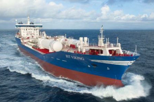
The vessel is outfitted with an LNG fuel system comprising two LNG storage tanks with combined storage capacity of 1 000 m3. The storage tanks are located on the vessel’s deck. This also allows the bunkering of LNG at a rate of 430 m3 an hour.
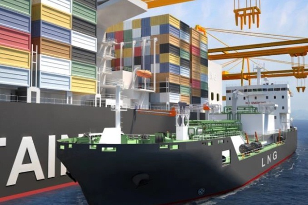
This specialized ship will have a capacity of 6 500 m3 and will be capable of fuelling 1 000 m3 of LNG per hour. As the market for LNG as Fuel increases in demand and LNG fuelled ships grow in LNG fuel capacity, the demand for LNG bunker barges will also naturally increase, with much higher capacities and available bunker rates when compared to LNG Trucks.
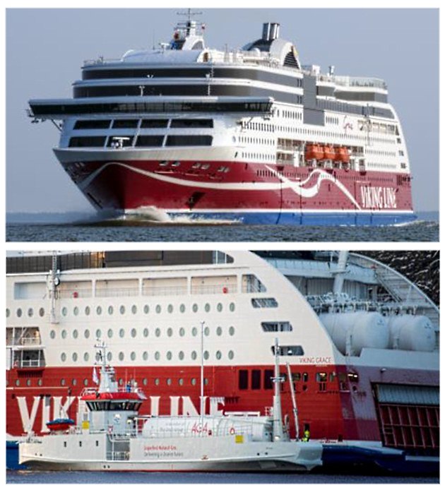
To note the LNG fuel tanks on the stern of the ship. The binomial “Receiving-Bunkering ships” is here seen as a clear indication of an LNG bunkering market in early stage of development. In the presented case the Seagas bunker vessel is dedicated to LNG supply to the Viking Grace. With a very significant number of successful operations conducted, the presented case is the example of a customized LNG bunkering solution has resulted in an exemplar safety case.
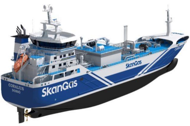
Bunker vessel with a cargo capacity of 5 800 m3 and is 99,6 meters long. She holds a Finnish/Swedish Ice Class 1A and is classed “LNG gas carrier IGC type 2G -165 °C, 500 kg/m3“. Larger volumes of LNG are transferred at high rates with Coralius representing a new paradigm in flexibility for higher and diversified LNG bunkering demands.
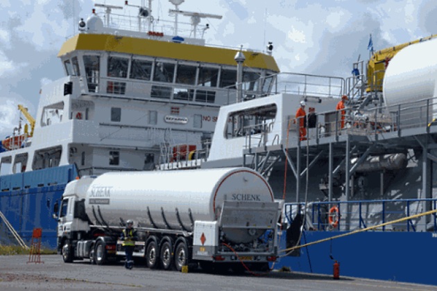
By far the most common method used today, representing an option that has allowed flexible operations and experience to build up. Notwithstanding adequate for limited LNG quantities LNG trailer trucks are typically limited to around 25ton of LNG (around 50 m3).x truck-to-ship LNG bunkering is unable to respond to higher demands in capacity or LNG transfer rates. As ships become more demanding for higher LNG volumes the transition to LNG bunker vessels or fixed LNG bunkering facilities will naturally take place.
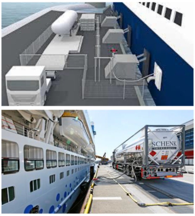
Variations of typical LNG Functional and General Requirements for LNG Bunkering Operationtruck-to-ship bunkering have also been developed, remarkably on what is called in the present guidance of LNG “feeding”, as presented in these two images, one artistic impression and another one, on the right, of actual operation. With LNG feeding the ship, otherwise with no LNG storage capacity on board, receives LNG directly from a truck trailer to consumption onboard. This allows the Health, Environment and Safety Management for LNG Transportships environmental profile at berth to be significantly improved, consuming cleaner burning natural gas, instead of oil fuels in port generators.
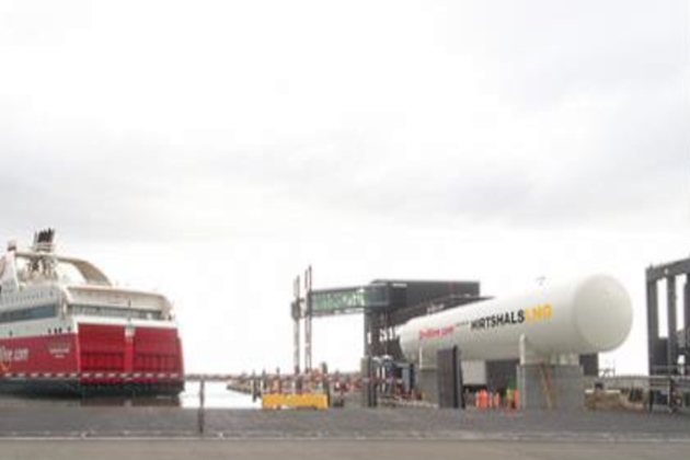
Having presented mobile LNG bunkering facilities, in Fig. 7, above, a fixed LNG bunkering location is shown, with type-C LNG tank. EU TEN-T co-financed pilot fixed LNG bunkering installation of 200 tonnes/445 m3 tank capacity Max Flow rate delivery of 200 m3/hour.
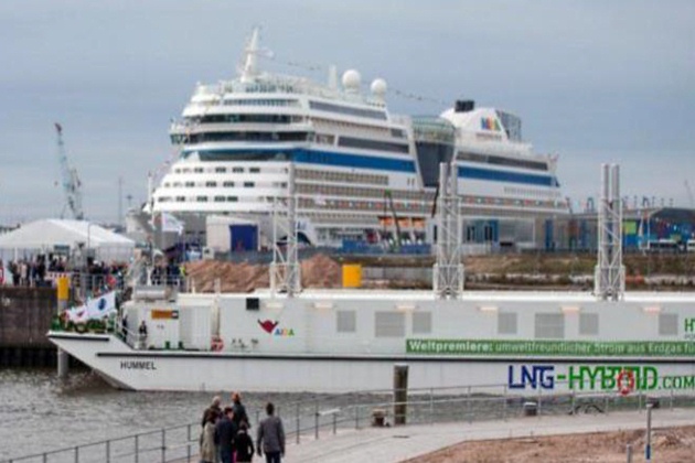
Even though not an LNG bunkering typical scenario, LNG fuelled electricity supply is also included in the context of this document. It involves typically mobile units such as the one presented – power barge supplying electricity from gas dual-fuel generators onboard, directly to the cruise vessel alongside in a close position.
Even though outside the scope of this document, the LNG bunkering market development is an important aspect that PAAs will have to consider. On one hand the number of ships that can be expected in a near future to be built, converted, or prepared for LNG as fuel.
Read also: Floating LNG Terminals General Overview
Currently it is possible to obtain information on the prospects of LNG as fuel from different sources, not only on the number of ships built and operating on LNG but also on the infrastructure development. These two aspects are often regarded as interdependent and should, from a practical point of view also be considered as relevant information elements to PAAs evaluating, promoting or assessing a prospective LNG bunkering facility project.
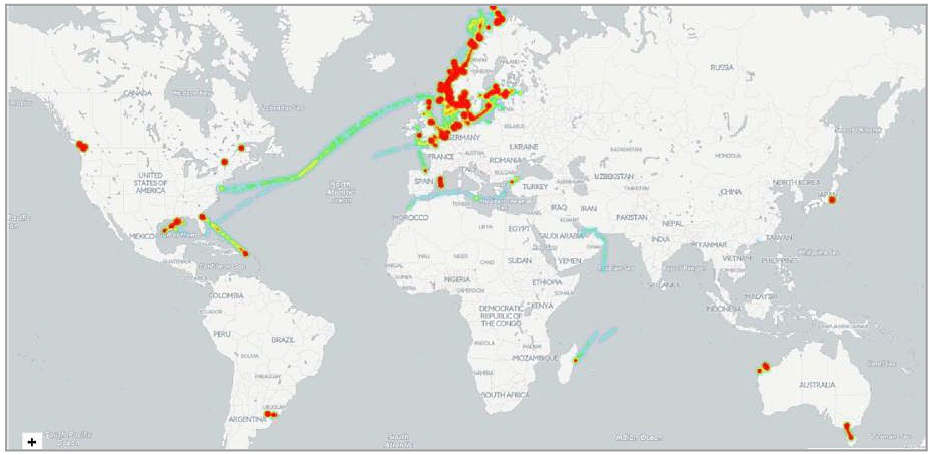
The number of LNG fuelled ships, in operation and on order is presented in figure 9, whilst figure 10 shows the areas of operation, based on AIS information, where LNG fuelled ships operate today.
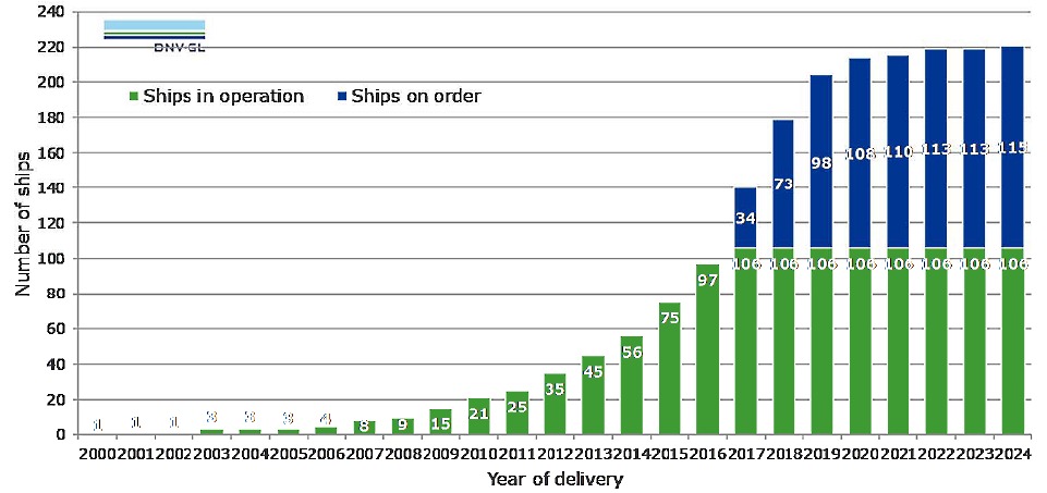
It does not go unnoticed from figure 9 that Ship conversion to use Liquefied Natural Gas as FuelLNG-fuelled ships in operation and on order have reached a maximum growing rate between 2014 and 2016, having recently stabilized mainly due to a reduction in oil fuel price driving shipowners to either delay the decision to convert to LNG or to choose another technical option for compliance with emission regulations. The future is however uncertain and, for the purpose of the present document, the important aspect to retain is that LNG as fuel will be an increasingly generalized option adopted in shipping. This reflects in the diversification of the LNG as an off-grid fuel solution for The business of LNG and historical involvement in maritime transportation of gasmaritime transport.
An important aspect for the development of LNG as fuel is the infrastructure. The small-scale developments are therefore important in the definition of LNG bunkering facility projects and, consequently, for the sizing and specification of the adequate LNG bunkering solutions within a port.
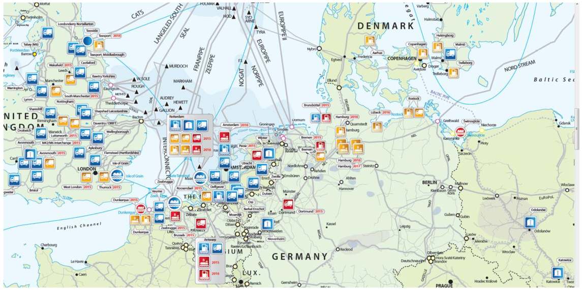
An adequate overview of the LNG small-scale infrastructure is therefore important to PAAs. The GLE small-scale LNG map provides the LNG industry and interested parties with an overview of the available, under construction and planned small-scale LNG infrastructure and services in Europe.
The GLE small-scale LNG map provides the following information:
| LNG import terminals offering new LNG services: | Reloading: Transfer of LNG from the LNG reservoirs of the terminal into a vessel. |
| Transhipment: Direct transfer of LNG from one vessel into another. | |
| Loading of bunker ships: LNG is loaded on bunkering ships which supply to LNG-fuelled ships or LNG bunkering facilities for vessels. | |
| Truck loading: LNG is loaded on tank trucks which transport LNG in smaller quantities. | |
| Rail loading: LNG is loaded on rail tanks which transport LNG in smaller quantities. | |
| LNG small-scale liquefaction plants: | LNG is produced in small scale liquefaction plants to respond to peak shaving demand or make available natural gas to regions where it is not economically or technically feasible to build new pipelines. |
| LNG bunkering facilities for vessels: | This stationary facility allows ships to bunker LNG to be used as fuel for the vessel. |
| LNG bunker ship: | This ship supplies LNG directly to LNG-fuelled ships or to LNG bunkering facilities for vessels. |
| LNG refuelling stations for trucks | This facility allows trucks to fill LNG to be used as fuel. |
| LNG satellite storage: | They enable to store LNG in small quantities in areas where there is no high pressure pipeline. LNG is delivered mainly by trucks (but also by small LNG ships) to these satellite plants where it is then stored and regasified into the natural gas distribution networks or used by an end user. |
LNG Characteristics
LNG Liquefied Natural Gas Commercial Considerations(liquefied natural gas) is the name given to natural gas that has been converted to liquid form by being cooled to a very low temperature. To attain a liquid phase, the temperature must be lower than the critical temperature (-82 °C in the case of methane). LNG is typically stored at near-atmospheric pressure at close to its atmospheric boiling point (-160 °C). In liquid form, natural gas occupies 600 times less volume that in a gaseous state, making it easier to transport over long distances and enabling a large storage capacity to be achieved in a relatively small space.
The main characteristics and hazardous properties of liquefied and gaseous natural gas are summarised in table 1 and discussed in the paragraphs below.
| Table 1. LNG Physicochemical properties | ||
|---|---|---|
| Properties | Notes | Value |
| Physical State | Cryogenic liquid under special PVT conditions | cryogenic liquid |
| Boiling Temperature at 1 bar [°C] | This is the temperature at which the vapour pressure of the material equals ambient pressure. Pure substances boil at specified pressure at a defined temperature. This temperature stays constant under continued addition of heat until all material is vaporised. Mixtures usually have a boiling range. | -161 |
| Density at 15 °C [kg/m3] | Density at (-160 °C, 1 bar) | 448 |
| Lower Heating Value [MJ/kg] At (-162 °C and 1 bar) | LHV gives a measure of the energy density by mass of the fuel. This parameter impacts on storage space in conjunction with density but can also provide an indication of the amount of heat released in a fire in conjunction with heat of evaporation. LNG has an LHV of 50 MJ/kg which 15 to 20 % higher than that of HFO and MGO. Thus approximately the same LNG fuel by weight must be bunkered to obtain the same energy on board. With respect to fire, the higher LHV of LNG implies that more heat will be released per mass of fuel as compared to MGO and HFO. | 50 |
| Vapour Density air = 1 | This parameter is interesting in order to gauge whether a vapour is likely to sink and accumulate in low areas or rise and accumulate in high areas. Methanol vapour density is very close to that of air, so it is near to neutral in buoyancy. The vapour density of anhydrous ethanol is 1,6, which is heavier than air. As LNG is at ambient conditions gaseous, but stored at less than -160 °C the vapour density discussion is more complex. Should a spillage occur the cold vapours may initially be heavier than air until they have warmed up sufficiently? Liquid density of LNG at -160 °C and 1 bar is 448 kg/m3. At 1 bar abs and -162°C pure methane is in subcooled condition. Gas density of pure methane at 0°C and 1 bar (normal conditions) is 0,71 kg/m3 (superheated condition). | 0,55 |
| Flash Point (TCC) [°C] | Flash point is the lowest temperature at which a liquid gives off enough vapour at the surface to form an ignitable mixture in air. Flash point is one of the valid indicators of the fire hazard posed by the fuel. The flashpoint of LNG at -175 °C is much lower than any oil fuel, and even much lower than other low flashpoint fuels such as methanol (12 °C) or even ethanol (17 °C). The challenge is therefore not to avoid formation of vapour due to heating of LNG but rather to manage, contain and, ultimately, use the generated vapour. | -175 |
| Auto Ignition Temperature [°C] | The auto ignition temperature is defined as “the temperature at which a material self-ignites without any obvious sources of ignition, such as a spark or flame. It is a function of the concentration of the vapour, the material in contact and the size of the containment. | 540 |
| Flammability Limits [by % Vol of Mixture] | Flammability limits give the range between the lowest and highest concentrations of vapour in air that will burn or explode [v]. Methanol’s flammability limits are wider than those of ethanol, LNG, and MGO | 4,5 – 16,5 |
| Min. ignition energy at 25 °C [mJ] | This is the lowest amount of energy required for ignition. This parameter is highly variable and dependent on temperature, amount of fuel and the type of fuel. Methanol, ethanol, and LNG all have minimum ignition energy below 1 mJ at 25 °C, whereas for MGO it is 20 mJ. | 0,29 |
| Flame temperature (°C) | Temperature attained to lean burning LNG pool fire | 1 875 |
Composition
LNG is typically a mixture of hydrocarbons consisting mainly of methane with smaller fractions of inter alia ethane, propane and nitrogen. The LNG imported to Europe typically consists of methane (90 weight percent) and ethane (10 weight percent). Components such as water vapour, carbon dioxide and heavier hydrocarbons have already been removed from the LNG.
It will be interesting: Guidelines for Automatic Cargo Tank Overfill Protection Aboard Gas Carriers
When the LNG is vaporised, it is methane that is first released as vapour. This is due the difference in atmospheric boiling point between methane and ethane. More precisely, the vapour will consist almost entirely of pure methane as long as no more than around 70 % of the liquid has been vaporised.
Physicochemical Properties
Methane is a colourless and almost odourless gas. When LNG is released into the environment, cold vapours are formed that result in condensation of the water vapour present in the air. This phenomenon means that LNG vapour is visible at low temperature due to the mist created.
The cold vapours formed by the vaporising of LNG are initially heavier than air and disperse close to the ground. As they mix with the ambient air, the cold LNG vapours gradually heat up and will behave neutrally at temperatures of around -110 °C, eventually becoming lighter than air under normal pressure and temperature conditions. At ambient temperature and pressure, Liquefied Natural Gas and Gas Contractsnatural gas has a density of around 0,72 kg/m3.
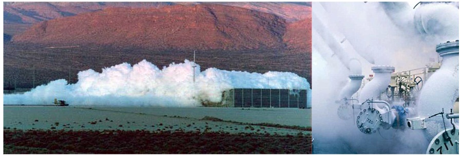
Figures 11 and 12 LNG cloud formation and progression (on the left) opposed to the condensation cloud formation around Pipelines in Marine Terminals: Key Considerations for Handling Liquefied GasLNG piping due to water vapour condensation in the air surrounding the cryogenic cold piping system
Condensation cloud formation around LNG piping, hoses, and manifolds is the result of water condensation surrounding cryogenic temperature elements of the LNG bunkering interface. The less insulated the bunkering lines are, and the more humid the surrounding atmosphere, the more condensate cloud formation and frost cap around piping will be generated.
Hazardous Properties
LNG vapour in air is flammable within specific concentration limits. As LNG vapour consists mainly of methane, the flammability limits of methane (4,5 – 16,5 vol. %) are generally used to estimate the size of the flammable clouds formed after an incidental release of LNG.
It should also be noted that free natural gas clouds, once ignited, burn at a relatively low speed, which means that only relatively small overpressures are likely to occur in an open environment (≤ 50 mbarg). Only if the flammable natural gas cloud formed is confined or is present in an installation with a high obstacle density may higher overpressures possibly occur in the surrounding area.
A pool fire or jet fire that occurs after an incidental release of LNG is characterised by a bright flame (little soot formation) and high radiation intensity (typically: 200 – 300 kW/m2). The effects of an LNG fire on nearby people or installations are therefore greater than those of fires that occur after an incidental release of conventional fuels such as petrol or diesel.
Finally, it should be noted that direct contact with LNG (as a cryogenic liquid) can result in serious freezing injuries. If LNG comes into contact with steel, the steel will embrittle due to the low temperature and a steel structure may fracture. Stainless steel retains its ductility at low temperatures and is therefore more resistant to contact with cryogenic liquids.
LNG Value Chain
From Natural Gas source to final consumers the LNG value chain can assume different shapes and be designed in different ways, depending on the needs for a variety of end-users. Figure 13 below shows a very simplified representation of a generic value chain, distinguishing between two different types of consumers:
- LNG;
- NG consumers.
These typically represent the transport and domestic/industrial users, respectively.
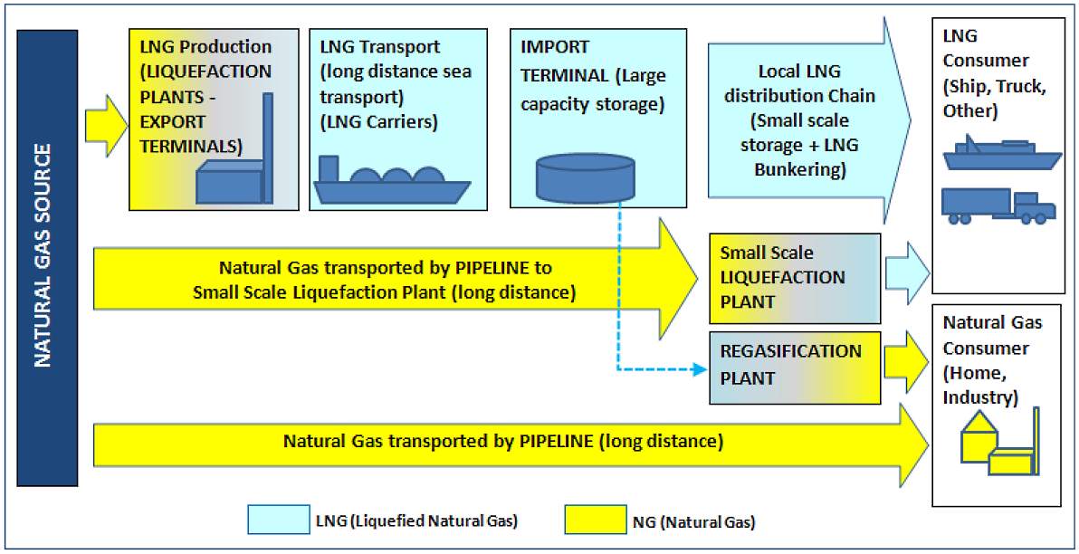
The chain is characterized by the liquefaction and re-gasification points where NG transforms into LNG and vice-versa. The need for LNG is associated with 2 (two) essential needs:
- the need to transport NG through long distances or;
- the need to provide NG for mobile users. Since LNG occupies 600 times less volume than NG it is also convenient for storage wherever limited space is available. This is obviously the case for ships, and other mobile units, but can also be the case for land-side developments, off-grid, potentially close to shore where LNG use may be convenient.
There are several aspects to be carefully considered when designing an LNG chain, but one main rule applies: The more interfaces, liquefaction plants, distribution links, the more likely it will be to have LNG accidental or operational releases. In Liquefied Natural Gas Reliquefaction Plantliquefaction plants LNG compressors are likely to have small LNG leaks leading to undesired methane emissions. In addition to the potential environmental impact it is also important to have safety into consideration, remarkably where the more transitions in phase and interface operations will represent also a potentially higher risk of accidental releases.
Read also: LNG System Features and Controls
Finally, it is important to note that a significant part of the LNG value chain can be contained within the boundaries of a Port and, especially if a multi-modal hub he tendency to have multi-modal hubs where LNG is supplied to different transport mode units will be potentiated by the TEN-T network, where EU core ports also represent relevant multi-modal nodes in the network.x is also included, it will very likely be seen the co-existence of different stakeholders in the port area. Port rules and local regulations should not only have this notion into account but also realize the different regulatory frameworks that may be relevant for different parts of the LNG chain. Fixed LNG bunkering facilities and mobile units may coexist, giving the exact expression to the versatility of LNG as fuel.
The LNG value chain, from an import grid or natural gas network distribution, can be further decomposed into different supply routes. Figure 14 exemplifies a possible representation of different supply routes.
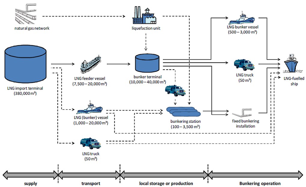
Different stages are considered which can be generically taken as the example from the figure:
- Supply;
- Transport;
- Local storage or production;
- and Bunkering.
We are only taking LNG fuelled vessels as the consumers in the diagram represented. In reality, however, this would be a multi-consumer environment that would be able to access LNG/NG from any point in the LNG chain.
LNG Bunkering, as an end-service within the LNG Value Chain will dictate, through demand, the shape of the local storage/production, whether trucks suffice, on a regular or spot delivery for bunker, or even whether local storage needs to be considered. Demand in terms of capacity (in total or per operation) will have to be considered, in this sense, at a very early stage. A careful consideration to the LNG Value Chain end, will avoid undesired operational losses, inadequate solutions and, ultimately, safety.
Elements affecting the LNG Value Chain
The following elements are considered as determinant in the shape and requirements for an LNG Value Chain:
- Consumer characteristics (location(s), consumption profile, cost vs. feasibility).
- Gas availability requirement.
- Supply (location(s), suitability, cost).
- Receiving terminals (need for break-bulk, location, type, sizes, investment cost).
- Shipping (vessels available, charter rate, fuel consumption).
- Boil-off gas (BOG) handling.
- Distance for LNG distribution (will dictate the distribution/transport mode for LNG) – the longer the distance for LNG distribution the higher should be the investment in insulation and, potentially, also the need for intermediate storage, liquefaction and refrigeration.
- LNG truck-trail loading in points where LNG road-rail mobile units load LNG for break-bulk distribution.
- LNG transhipment Transhipment – operation technically similar to simultaneous unloading and loading – can be used to divide a large cargo into smaller ones (break-bulking), or to optimise the LNG tanker fleet between the sellers and buyers of a cargo (ship swap). Transhipment may also be called “Ship-to-Ship” (STS), even if STS usually refers to offshore cargo transfer through flexible hoses between side-by-side vessels. Transhipment is not covered by this Guidance as it deals with LNG as cargo, even if it may represent the break-bulk of cargo into smaller feeder vessels. Some of these feeder vessels may however be involved themselves in the delivery of LNG broken bulk to LNG bunkering providers.x from larger scale LNG carriers to medium-smaller LNG feeder vessels or even LNG bunker vessels or barges.
- How far apart are end users/consumers from LNG Import Terminal? This will dictate how smaller scale LNG bunkering will develop and how will distribution of LNG be done to avoid losses and to minimize the number of transformation points.
Scale of LNG developments and facilities
In the context of this Guidance the scale of an LNG development/facility is often mentioned, in particular with reference to “small scale” LNG facilities. In the absence of exact criteria that would help to determine a separation between small, medium and large scale LNG developments, this Guidance establishes, as an indicative reference the single criteria approach, using for classification the LNG storage capacity of a given LNG facility. The whole scope of this Guidance is contained in the Small scale interval, with Shore Natural Gas Storage TanksLNG storage capacities involved, either in pressurized or atmospheric tanks well below 10 000 m3.
| Table 2. Scale of LNG developments and facilities (single criteria: storage capacity) | ||
|---|---|---|
| LNG Scale | LNG Storage capacities typically involved | Operations |
| Large | > 100 000 m3 | Liquefaction plant: A large-scale LNG operation typically includes production trains with single capacities between 1 and 6 MTPA (million metric tonnes per annum), and they can include multiple trains. Large liquefaction sites are always located in coastal areas since the only practical method of large-scale transportation is using LNG carriers, with capacities ranging from approximately 120 000 m3 (54 000 tonnes) for older vessels to up to as much as 267 000 m3 (120 000 tonnes) for the largest Q-max vessels. |
| Receiving terminal: Conventional receiving terminals (LNG hubs) in the large-scale LNG chain are also located by the coast so that LNG carriers can arrive and unload the cargo. Main hubs include LNG storage facilities, typically in the range of 120 000 m3 or larger, designed to receive at least the full capacity of the allocated LNG carrier. The LNG is regasified at the hub, and the main distribution channel for the consumers is normally a national, high-pressure, natural gas pipeline. | ||
| Medium | 10 000 to 100 000 m3 | A medium-size LNG logistics chain includes terminal up to 100 000 m3 in size, which are supplied by small-scale LNG carriers, starting from sizes of 1 000 m3 to up to around 40 000 m3. Here again, the vessel size and loading frequency play an important role in determining storage capacity. |
| Medium-scale liquefaction is not so common today, due to the challenge with high, specific production costs. In any case, these will probably play a larger role in the future for decentralised solutions, to which extending the large-scale logistic chain would not be feasible. | ||
| Small | < 10 000 m3 | A small-scale LNG logistics chain is comprised of LNG distribution to local users. In practice, this means highway truck transportation or small sea-going vessel distribution to the end-user’s local LNG tanks, which can be from the smallest container sizes of 20 m3 to up to a set of pressurised steel tanks with total capacities of up to a few thousands of cubic metres. |
| Small-scale liquefaction is becoming popular due to the liquefaction of biogas and other smaller pockets of stranded gas. Small-scale liquefaction can be modularised and, to some extent, standardised. The systems are similar to the re-liquefaction process used in large terminals to handle the BOG (boil-off gas). | ||

- Study on the completion of an EU framework on LNG-fuelled ships and its relevant fuel provision infrastructure, LOT 1 Position paper: Towards harmonized EU LNG bunkering guidelines, DNV-GL, 2016.
- Study on the completion of an EU framework on LNG-fuelled ships and its relevant fuel provision infrastructure, LOT 1 Final Report, DNV-GL, 2016.
- LNG Bunkering Guidelines IACS Recommendation n. 142, on LNG Bunkering, IACS, 2016.
- ISO/TS 18683:2015. (15-Jan. 2015). Guidelines for systems and installations for supply of LNG as fuel to ships. Technical Specification.
- Society for Gas as a Marine Fuel (SGMF). (2015). Gas as a marine fuel, safety guidelines, Bunkering. Version 1.0, February 2015.
- ISO 20519:2017. Ships and marine technology – Specification for bunkering of gas fuelled ships. (International Standard).
- IEC 60079-10-1. (2015). Explosive atmospheres – Part 10-1: Classification of areas – Explosive gas atmospheres.
- Directive 1999/92/EC – ATEX of the European Parliament and of the Council of 16 December 1999 on minimum requirements for improving the safety and health protection of workers potentially at risk from explosive atmospheres (15th individual Directive within the meaning of Article 16(1) of Directive 89/391/EEC).
- API RP-500. 1997. Recommended practice for classification of locations for electrical installations at petroleum facilities classified as CIass 1, Division 1 and Division 2. Washington. D.C: API.
- API RP-505. 1997, Recommended practice for classification of locations at petroleum facilities classified as Class I, Zone 0, Zone 1 and Zone 2. Washington, D.C. API.
- NFPA 497. 2012, Recommended practice for the classification of flammable liquids, gases or vapours and of hazardous (classified) locations for electrical installations in chemical process areas. Quincy, MA: NFPA.
- IEC EN 60079-10-1 Ed.1.0, 2008. Electrical apparatus for explosive gas atmospheres – Part 10-1: Classification of areas – Explosive gas atmospheres. International Electrotechnical Commission.
- Commission Decision 2010/769/EU of 13 December 2010 on the establishment of criteria for the use by liquefied natural gas carriers of technological methods as an alternative to using low sulphur marine fuels meeting the requirements of Article 4b of Council Directive 1999/32/EC relating to a reduction in the sulphur content of certain liquid fuels as amended by Directive 2005/33/EC of the European Parliament and of the Council on the sulphur content of marine fuels (OJL 328, 14.12.2010, p. 15).
- USCG CG-OES Policy Letter 02-14 – Guidance Related To Vessels And Waterfront Facilities Conducting Liquefied Natural Gas (LNG) Marine Fuel Transfer (Bunkering) Operations.
- ADN – European Agreement concerning the International Carriage of Dangerous Goods by Inland waterways (Update version ADN January 2017).
- ADR – European agreement concerning the International Carriage of Dangerous Goods by Road (Update version ADR January 2017).
- Rhine Vessel Inspection Regulations (RVIR).
- EU general risk assessment methodology (Action 5 of Multi-Annual Action Plan for the surveillance of products in the EU (COM(2013)76) – Document 2015-IMP-MSG-15 – 16 October 2015.
- Safety Study, Chain analysis: Supplying Flemish ports with LNG as a marine fuel, Analysis of safety aspects, June 2012.
- EN 1160 – Installations And Equipment For Liquefied Natural Gas – General Characteristics Of Liquefied Natural Gas, NBN, 1st edition, August 1996.
- ESD Arrangements & Linked Ship/Shore Systems for Liquefied Gas Carriers, SIGTTO First Edition 2009 – SIGTTO.
- M. Kofod & S. Hartman, T. Mundt – Review of Recent Well-to-Wake Greenhouse Gas Studies evaluating the use of LNG as a marine Fuel, IMO MEPC/INF.15.
- LNG Access Code for Truck Loading for The Zeebrugge LNG Terminal – Based on version approved by the CREG on September 19th 2013 – Applicable as of January 1st 2014 – FLUXYS.
- Guidance for the Prevention of Rollover in LNG Ships – SIGTTO – First Edition 2012.
- Wang, Siyuan & Notteboom, Theo – The role of port authorities in the development of LNG bunkering facilities in North European ports, 14 January 2015, World Maritime University 2015.
- Verhoeven P (2010) A review of port authority functions: towards a renaissance? Marit Policy Manag 37:247-270.
- Society for Gas as a Marine Fuel (SGMF). (2017). Gas as a marine fuel, safety guidelines, Bunkering. Version 2.0, February 2015.
- COM(2003) 515 final – Communication from The Commission concerning the non-binding guide of good practice for implementing Directive 1999/92/EC of the European Parliament and of the Council on minimum requirements for improving the safety and health protection of workers potentially at risk from explosive atmospheres, Brussels, 25.8.2003.
- Davies, P. (2016) – Bunkering LNG: Setting the Safety Zone, 7th Motorship Gas Fuelled Ships Conference, November 2016.
- International Association of Oil & Gas Producers. (1-Mar 2010). Risk Assessment Data Directory – Process Release Frequencies. Report No. 434 – 1, 1 March 2010). Pertinent data from this report is summarised in: Davies & Fort, (Sept 2012), LNG as Marine Fuel – Likelihood of LNG Releases, Journal of Marine Engineering and Technology.
- PGS2 – TNO Yellow Book – Methods for the calculation of physical effects, due to releases of hazardous materials (liquids and gases) – CPR 14E (3rd Edition, 2005) – TNO – The Netherlands Organization of Applied Scientific Research.
- OECD Guiding Principles for Chemical Accident Prevention, Preparedness and Response, Guidance for Industry (including Management and Labour), Public Authorities, Communities, and other Stakeholders – 2nd Edition (2003) – OECD Environment, Health and Safety Publications.
- DNVGL-RP-G105 Edition October 2015 – Development and operation of liquefied natural gas bunkering facilities, Recommended Practice, DNV GL, 2015.
- USCG CG-OES Policy Letter No. 01-17 – Guidance for Evaluating Simultaneous Operations (SIMOPS) during Liquefied Natural Gas (LNG) Fuel Transfer Operations.
- LGC NCOE Field Notice 01-2017 – 14-Aug-17 – Recommended Process For Analysing Risk Of Simultaneous Operations (SIMOPS) During Liquefied Natural Gas (LNG) Bunkering.
- An Overview of Leading Software Tools for QRA, American Society of Safety Engineers – Middle East Chapter (161), 7th Professional Development Conference & Exhibition, March 18-22, 2005.
- Walter Chukwunonso Ikealumba and Hongwei Wu (2016) Some Recent Advances in Liquefied Natural Gas (LNG) Production, Spill, Dispersion, and Safety School of Chemical and Petroleum Engineering, Curtin University.