Future of Liquefied Natural Gas Industry is very bright, because increasing LNG demands from many parts of the world because LNG is now considered safe and is less polluting. The demands are to be met by an increase in new liquefaction plants that are based on the unconventional gas and new discoveries. The new liquefaction plants under consideration will be built with higher efficiency in an environmentally responsible manner. This means the whole LNG supply chain, from the well heads, gas treatment, liquefaction, transportation, and regasification must be designed and configured with low emissions and high efficiency. Additionally, there is also a drive to lower the cost of natural gas liquefaction and improve the value of the LNG regasification plant.
- Introduction
- Innovations in LNG liquefaction
- Larger trains
- Main exchanger size
- Liquefaction pressure
- NGL recovery
- Liquid expander
- Matching drivers
- Colder climate design
- Future LNG plants
- Gas turbines
- CO2 emissions
- Performance impacts from ambient temperature changes
- Application to LNG industries
- Emissions from ship propulsion system
- Electric motor drive
- Combined cycle power plant
- Gas turbine inlet air chilling
- Gas turbine exhaust duct firing
- Modularization
- LNG regasification
- LNG industrial complex
- LNG wobbe index
- LNG and CNG vehicle fuel production
- Integrated LNG regasification/power generation
- LNG ambient air vaporizer
- LNG new berthing designs: jetties and subsea pipelines
- Offshore loading and unloading hose
Introduction
The earlier LNG production plants were based on proven technologies and operation tracking records. There have not been significant changes in the LNG plant design. This is understandable as the investment risk with natural gas liquefaction is large, and conservative designs are necessary. With the escalating energy costs, as natural gas prices are now pegged to oil price, the emphasis is on efficiency and lower production cost. However, recent cost overruns with large LNG plants makes investors rethink the project economics of large plants, most likely refocusing on the less expensive mid-sized plants.
On the liquefaction technology, there are recent developments in driver technologies that will change the liquefaction unit design and configuration, such as more efficient gas turbine drivers, aeroderivative turbine drivers, proven large motors, and the efficient combined cycle power plant. There are also innovations in gas treating technologies in processing sour gases.
On the regasification side, there are also advances and developments. Floating regasification and storage carriers appear to be less costly than land-based facilities. Emphasis is on LNG cold utilization to improve the overall Offshore supply chain of Liquefied Natural GasLNG supply chain efficiency, such as cryogenic power generation, air separation plants, boil-off gas condensation, and integration to industrial complexes. The greenhouse gas emis-sions from fuel gas fired combustion vaporizers and the impact on marine life with cold water discharge from seawater vaporizers are environmental concerns. The use of ambient air vaporizers is now considered to be more environmentally friendly.
This chapter discusses the development, advances, innovations, and new ideas in the LNG supply chain. The focus will be on more efficient liquefaction technology, larger and higher efficiency drivers, improved liquefaction equipment design, NGL recovery, LNG regasification, and LNG cold utilization. The applications of some of these technologies may further improve the image of the LNG industries.
Innovations in LNG liquefaction
Larger trains
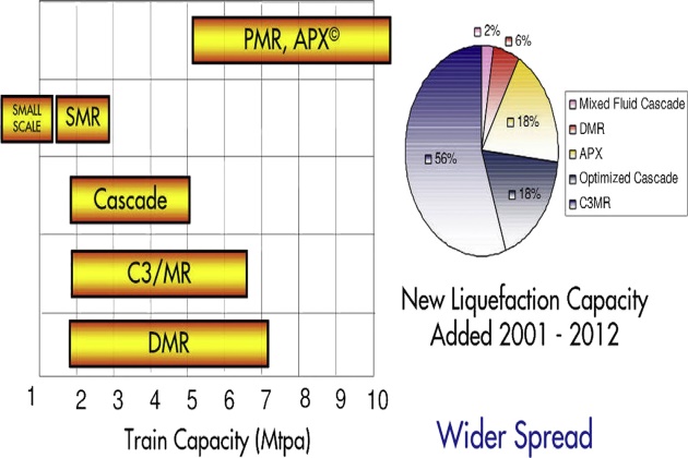
For economy of scale, the trend is to construct a larger train size. The LNG industry has taken a big step toward increasing train capacity with the implementation of the AP-XTM process in Qatar in 2008. Six trains were constructed, each with a nameplate capacity of 7.8 MTPA. Today’s APX trains are becoming even larger with more drivers and improved liquefaction design, as shown in Figure 1.
The AP-XTM process is an extension of the C3MR process, maintaining its proven performance while increasing the train capacity. The configuration of the cycle is shown in Figure 2. In this process, propane is used for precooling, while natural gas is liquefied and partially subcooled in the main cryogenic heat exchanger (MCHE) with a mixed refrigerant.

Final subcooling is accomplished by using a nitrogen expander loop. Nitrogen is compressed to a high pressure, cooled to ambient temperature, and further cooled by low pressure nitrogen before being expanded to a lower pressure. The nitrogen provides refrigeration for subcooling LNG. By using nitrogen to subcool LNG, the percentage of the total refrigeration load on the upstream C3MR section is reduced, allowing for greatly increased capacity in a single train without having to parallel major equipment. With today’s larger gas turbine drivers, and the large heat exchanger designs, a train size over 10 MTPA is now feasible.
The AP-XTM process is claimed to achieve high efficiency and low production cost by using all three refrigerant cycles to their best advantage. Bronfenbrenner et al. (2009) compared the thermodynamic efficiencies (power required/ton of LNG produced) of the main gas liquefaction process. On a relative basis, they claimed that the C3MR, AP-X and DMR processes offer the highest efficiencies, with POCLP (Phillips Optimized Cascade LNG Process) offering about 90 %, SMR offering about 80 %, and expander technologies offering about 70 %, respectively, of the effi-ciencies achievable by C3MR and others. On the other hand, thermal efficiency studies conducted by ConocoPhillips on the POCLP disagree with such findings.
Read also: International trade of Liquefied Natural Gas in maritime industry
Thermodynamic efficiencies of the refrigeration cycles are frequently compared among different processes. But the meaningful comparison should be made in consideration of the overall utility consumption instead of the cycle, particularly when high efficiency cycles are considered.
Main exchanger size
Several years ago, the maximum main cryogenic exchanger size was limited to a diameter of 4.6 m and a maximum exchanger weight of 310 tonnes. This was the maximum exchanger size necessary in order to achieve the required LNG train production, which had been limited by the power available from the compressor drivers. As the drivers keep increasing in size, larger train capacity has been developed to take advantage of the driver power. Improvements have been made to the manufacturing technique, and currently the maximum exchanger diameter increases to 5.0 m, and the exchanger weight increases to 430 tonnes. These larger exchangers play a key role in increasing capacity of the liquefaction train beyond 8 MTPA.
Liquefaction pressure
Higher tube-side design pressure allows for higher operating pressures, which results in increased production and lower specific power for the same size heat exchanger. An increase in liquefaction pressure from 65 barg to 80 barg can increase the production by about 6 % and reduce the specific power by about 2 %.
NGL recovery
An NGL recovery plant can be integrated to the LNG liquefaction process using a scrub column design. However, the NGL recovery is low compared to a standalone unit. NGL recovery can be integrated to the LNG process using the more advanced NGL process. In the Qatargas II LNG project, Qatar Petroleum and ExxonMobil selected the conservative design using Ortloff SCORE process for propane recovery.
Each of the two 7.8 MTPA LNG trains receives feed gas from the North Field, which is the largest nonassociated gas field in the world. The onshore NGL plant extracts LPG (propane and butane), which is fractionated and exported from Ras Laffan. Lean LNG production was targeted for the UK market, which requires a lean LNG.
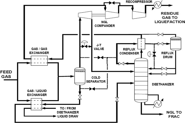
The NGL recovery used the SCORE (Single Column Overhead REcycle) process licensed by Ortloff Engineers, Ltd. This is an expander-based cryogenic process that has been applied in numerous plants worldwide. The NGL plant accomplishes the function of scrub column in a typical liquefaction process-for removal of C5+ prior to liquefaction. Accordingly, no scrub column is included in the LNG plant design. As a consequence, the liquefaction unit cannot operate without the NGL plant. Rich LNG production will still be possible by injecting the C3 and C4 back into the gas stream prior to liquefaction. Figure 3 shows a simplified process flow of the SCORE process for Qatargas II.
Ortloff’s SCORE process is primarily utilized as an efficient propane recovery technology. Propane recovery typically exceeds 97 %, with 99 % or higher easily achievable, while rejecting all the ethane. If ethane recovery is desired in addition to high propane recovery, SCORE can be operated in a partial ethane recovery mode by adjusting the amount of heat input to the column. This “incidental” ethane recovery mode is usually limited to about 40 % ethane recovery.
Liquid expander
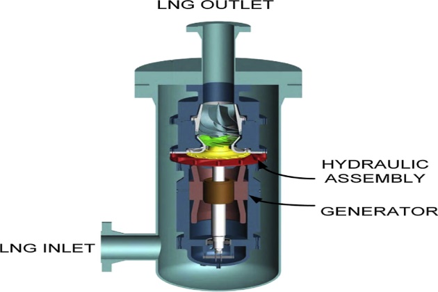
Liquid expander has been used in the gas processing industry for decades for the recovery of power and production of refrigeration. In the traditional LNG process, pressure reduction is typically by a Joule- Thomson valve, in refrigeration units or in the last stage of the end-flash process. Only recently, liquid expanders have been introduced to the LNG industry and are now accepted in new liquefaction plants and in retrofit of existing facilities, starting with MLNG (Tiga Liquefaction Complex in Bintulu, Malaysia) in 1996. The liquid expanders are essentially pumps that are run backward that allow a subcooled liquid to be expanded. Work of the expansion is extracted from the fluid as shaft power that can be used to drive a pump or generate electricity (Figure 4). The recovery of power is valuable, but more importantly, when the fluid expands, it also lowers the fluid temperature. This is particularly important when the fluid, either refrigerant or LNG, can be chilled to a lower temperature, reducing the amount of vapor flashing at the lower pressure, lowering the vapor compression requirement.
According to Cryostar, with the cryogenic liquid turbine, the total plant savings are between 1.5 and 5 %, depending on plant size and the process design, considering the additional production of liquid and the production of electricity.
Matching drivers
Optimizing the process/machinery configuration has played a major role in increasing LNG train capacity. Traditionally, the propane compressor and the mixed refrigerant compressors were driven by separate drivers (typically gas turbine drivers). Since operators prefer to use the same gas turbine drivers for maintainability, this driver configuration is not conducive to fully utilizing the available gas turbine power. In the recent liquefaction designs, such as RasGas Trains 3, 4, and 5 and Segas, the same driver is used to drive multiple refrigeration services and has improved the overall operability and cycle efficiency, making the process less dependent on driver selection.
With the advances of large motors, the gas turbine drivers can now be replaced with motors. Motors are available from different manufacturers and come in different sizes. This flexibility allows more optimum Development of Natural Gas Liquefaction Cycles based on Energy and Exergy Analysesliquefaction cycle designs, and the thermal efficiency is expected to be higher, consequently producing less emissions.
Colder climate design
Ambient conditions, such as air and water temperature, have significant effects on plant design. Plants have been located mostly near the equator, but newer facilities are now located in Arctic climates such as Norway and Russia. As ambient conditions change during the year, the LNG production is con-strained by limitations of mechanical equipment. The power produced by a gas turbine is also a function of the inlet air temperature, while the efficiency of the refrigeration system also improves with a lower ambient air temperature. For the colder climate areas, the average ambient temperature could be around 0 °C, but the yearly temperature swing can be from -40 °C to 30 °C.
The cold climate temperature influences the gas turbine power split between the propane refrigeration section for precooling and the mixed refrigerant section for liquefaction and subcooling. Typically, the equipment is designed for high ambient temperature, say 60 °F, and the power split is about one third for precooling and two thirds for liquefaction and subcooling. At 0 °C ambient, the split will shift to about one fourth for precooling and three fourths for liquefaction and subcooling. The challenges are in designing the heat exchanger equipment to fully utilize the higher power output from the gas turbines as well as the deeper chilling during the cold ambient months.
Future LNG plants
Large trains in the range of 8 to 9 MTPA can be justified only in locations with very large gas reservoirs. It is likely that trains in the capacity range of 3 to 6 MTPA will become more important in the future as the LNG plants are likely to be located in more areas and offshore and there is more emphasis on flexibility, efficiency, and operating and capital costs.
Most of the LNG train designs built in the past decade use single cycle heavy-duty gas turbines both as refrigeration compressor drivers and in the power generation plant. The waste heat from the gas turbine exhaust is used in steam generation for power generation and process heating. Any excess waste heat, if not used by the process, is rejected to the atmosphere.
Most of the earlier processes also use seawater for cooling, which is now known to have significant impact on the ocean environment. A more environmentally friendly approach is to use air instead of seawater for cooling even though it will increase the energy consumption by liquefaction.
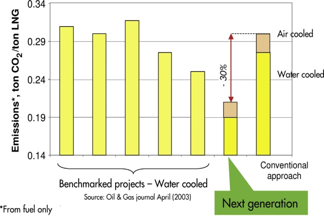
Today, the focus of innovation is shifted toward increasing energy efficiency, minimizing CO2 emissions and lowering overall environmental impacts. Large equipment sizes and higher capacities may no longer be the solution. The next generation of LNG liquefaction plants will have a lower carbon footprint using the high efficiency gas turbines, combined cycle power plants, large motor drives, and more efficient NGL/LNG integration (see Chapter 2). Air cooling should be used where possible to minimize impact on the ocean environment. Nonproprietary and more efficient heat exchanger equipment will be readily available from manufacturers from different countries. More liquefaction process choices will be available as the LNG industry moves toward the less costly but efficient mid-scale LNG plants.
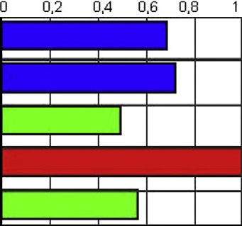
These advances in LNG production plant were predicted to be able to reduce CO2 emissions in the next generation LNG plants by at least 30 % as shown in Figure 5.
Gas turbines
Traditionally, industrial gas turbines are used as drivers for the refrigeration units. Aero-derivative gas turbines are thermally more efficient than industrial gas turbines and have been applied to power plant design. However, they have not yet been used as mechanical drives in LNG plants until recently. A list of the aero-derivative gas turbines and industrial gas turbines is shown in Table 1.
There are several advantages of the aero-derivative gas turbines. Aero turbines are lighter in weight and more compact than industrial gas turbines, which are favorable attributes for offshore installation. They are multishaft variable-speed machines, and can start under settle-out pressure without using starter/helper motors.
CO2 emissions
The higher efficiencies can be translated into lower CO2 emissions. Figure 6 shows the CO2 emissions from industrial gas turbines and aero-derivative gas turbines. The aero-derivative gas turbines, being more efficient, produce lower CO2 emissions than industrial-type gas turbines.

However, when the gas turbine exhaust is recovered and used in power generation or heating, the combined cycle power generation efficiency can approach 60 % (Section 10.2.12), which makes it the most efficient power plant in today’s technology.
Performance impacts from ambient temperature changes
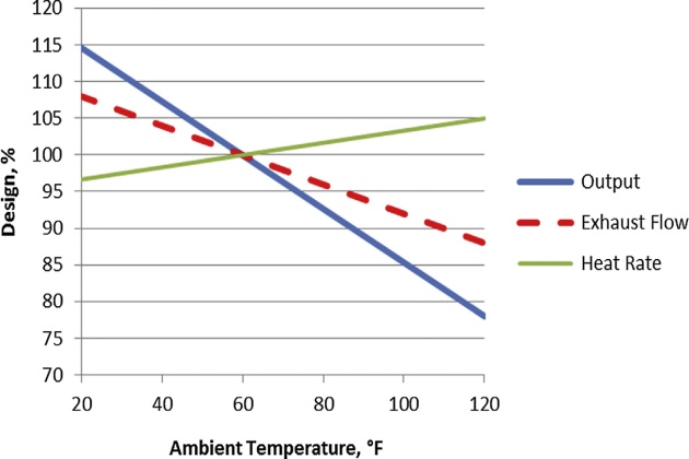
The power output of gas turbines varies with ambient temperature. Power output typically drops by about 0.3 % to 0.5 % for each °F increase in ambient temperature. Aero-derivative gas turbines are more sensitive to ambient temperature change than industrial gas turbines as shown in Figure 7.

Industrial gas turbines are less sensitive than aero-derivative turbines to ambient temperature changes. Typically, industrial gas turbines operate at lower pressure ratios than the aero-derivative counterparts. They also operate with a much higher air flow; consequently, temperature changes have less impact on power output. For example, on a 90 °F day, the power output of a frame unit operating at a pressure ratio of around 10 to 1 will decline by 8 or 10 % (from its standard 59 °F nameplate rating) as compared to a 15 % drop for an aero-derivative gas turbine operating at a 30 to 1 pressure ratio. In actuality, each gas turbine model has a unique power-temperature curve specific to its aerodynamic design that determines the power output, heat rate, and exhaust flow and conditions.
High ambient temperatures usually coincide with peak demand periods, which are especially detrimental during hot summer days when the reduction in power output is greatest. Inlet cooling offers a cost effective solution to offset power loss at high ambient temperatures. The effect of air cooling on power output is shown in Figure 7. As an example for a generic aero-derivative turbine, lowering the gas turbine inlet air temperature from 60 °F to 40 °F increases its power output by about 14 %. On the other hand if the air temperature is raised to 100 °F, the power output drops by about 30 %. The impact in power output is less for the industrial turbines since their firing temperatures are lower and are less efficient. For this reason, modern power plants installed in hot climate areas are equipped with an ambient air cooler in order to maintain the power output.
Gas turbine air cooling also helps to reduce degradation in heat rate, as shown in Figure 8. The heat rates are lower at the lower temperatures, which means less fuel is consumed and less CO2 emission is produced.
For example, reducing the inlet temperature from 60 °F to 40 °F reduces the heat rate by about 2 % or fuel efficiency by the same amount. At the same time, the exhaust flow from the gas turbine is increased by about 4 %, which means more waste heat is available for steam generation in the HRSG (Heat Recovery Steam Generation), further increasing the power output from the steam turbines.
Application to LNG industries
At the present time, aero-derivative gas turbines can achieve thermal efficiencies over 25 % higher than industrial gas turbines. This can result in a 3 % or higher increase in overall plant thermal efficiencies. The use of aero-derivative gas turbines to improve plant output or reduce greenhouse is very attractive. The drawbacks are the maintenance costs for an aero-derivative gas turbine and their lower reliability than industrial gas turbines. But as time passes, with more in operation, the costs and reliability are expected to improve.
Aero-derivative gas turbines were successfully deployed in the optimized cascade liquefaction trains of the Darwin LNG facility. Positive aspects are the improved plant availability as a result of the ability to completely change out an aero-derivative gas turbine generation set in less than three days versus 14-plus days that could be required for a major overhaul on an in-dustrial gas turbine .
Emissions from ship propulsion system
The CO2 emissions or energy efficiencies from the available engine choices for an LNG carrier propulsion system are given in Table 2. The use of steam turbines for propulsion is the least efficient method and emits the most pollutants. They were used in the earlier ships but are no longer used. The operation of a steam system also generates significant amount of waste water, which must be processed prior to discharge to the open sea.
The demand for larger and more energy efficient LNG carriers has resulted in rapidly increasing use of the Questions and answers to Crew Evaluation System Test about Sulzer Medium Speed Diesel Enginediesel engine as the prime mover, replacing traditional steam turbine propulsion plants. Two alternative propulsion solutions have established themselves on the market to date: low speed, heavy fuel oil burning diesel engines that can be combined with a reliquefaction system for BOG recovery and medium speed, dual-fuel engines with electric propulsion.
A further low speed direct propulsion alternative, using a dual-fuel two-stroke engine, is also available: high thermal efficiency, flexible fuel/gas ratio, and low operational and installation costs are the major benefits of this alternative engine version. The engine utilizes a high pressure gas compression system to supply boil-off gas at pressures of 250 to 300 bar for injection into the cylinders.
For many years, the LNG market has not really valued the boil-off gas, as this has been considered a natural loss and typically is burned in the steam boiler for the steam turbine movers. Generally, emission considerations favor the selection of the dual-fuel engine over the HFO (Heavy Fuel Oil) engine and, with today’s fuel prices, the dual-fuel gas injection engine is found to be an economical option. However, project specific factors, such as a requirement for a fixed amount of LNG to be delivered, need to be considered in specific cases, and may influence the balance between the gas injection engine alternative and the HFO engine alternative.
Electric motor drive
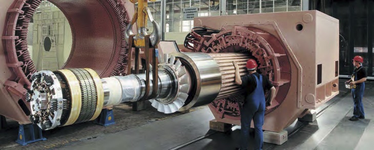
Traditionally, refrigeration system drivers are either by gas turbines or steam turbines. Motor drive is used for starter or helper motors in a large gas turbine driver. The helper motor drive for a GE Frame 7 the motor sizes are approaching the 100 MW range, motor drives are becoming cost competitive with mechanical drivers. The electric driven design is particularly attractive in the 5 to 8 MTPA capacity range. Electric motors of 65 MW have been developed for LNG service (see Figure 9), and motors up to 80 MW are now feasible.
Electric motor drives are more expensive than mechanical drives but have the following advantages:
- Electricity can be supplied from a combined cycle power plant, which is the most energy efficient power generation process, and can lower greenhouse gas emissions. The liquefaction process configuration is now independent from the gas turbine drive selection;
- Combined cycle power plants can be sourced from many manufacturers. Competitive design and equipment pricing are readily available;
- The dominance of a few liquefaction suppliers that ties to specific gas turbine drives is over. There are competitive designs that will lower the cost of the liquefaction plants;
- The plot plan of the refrigeration system is significantly reduced since the gas turbines and heat recovery equipment are located away in the power plant;
- The process safety is improved since there is no combustion equipment within the liquefaction plant;
- Motor drive is more reliable, eliminating downtime and shutdown/maintenance required by the gas turbine drive;
- Electric motor variable speed drive (VSD) provides turndown flexibility, reliability, and efficiency, which are important in LNG plants;
- Compared to gas turbine drives, motor drives are not sensitive to ambient temperature changes. Process design can be maintained as constant throughout the year.
Combined cycle power plant
The size of the combined cycle power plant is an important parameter in determining the LNG plant size. The larger plant sizes benefit from economies of scale (lower $/kW) and higher thermal efficiency. The combined cycle units can also be designed to produce extraction steam to supply steam to the process heating. A block diagram of an integrated combined cycle plant and LNG plant is shown in Figure 10.
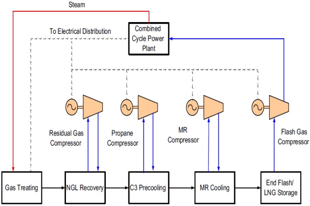
Figure 11 depicts a combined cycle power plant, courtesy of Siemens. The discharge from the gas turbines that are housed in a building is piped via a duct to the HRSG located in a structure on the left side.
There are several design configuration options for a combined cycle power plant:
- In a single shaft combined cycle plant, a gas turbine and a steam turbine can drive a common generator;
- In a multishaft combined cycle plant, each gas turbine and each steam turbine has its own generator;
- The multishaft design enables two or more gas turbines to operate in conjunction with a single steam turbine, which can be more economical than a number of single shaft units;
- A larger steam turbine also allows the use of higher steam pressures, more reheat stages, resulting in a more efficient steam cycle.
Thus the overall plant size and the associated number of gas turbines have a major impact on whether a single shaft combined cycle power plant or a multiple shaft combined cycle power plant is more economical.
Large gas turbines of over 150 MW size are already available by at least four separate groups: General Electric and its licensees, Alstom, Siemens, and Westinghouse/Mitsubishi. Combined cycle units are made up of one or more such gas turbines, each with a waste heat steam generator arranged to supply steam to single or multiple-steam turbines, thus forming a combined cycle block or unit. Typical combined cycle block sizes offered by these major manufacturers vary slightly but they all can achieve close to 60 % thermal efficiency. Their performances are compared in Table 3 using the GTPRO program from Thermoflow Inc., based on the gas turbine’s iso-conditions (60 °F). Note that actual power plant outputs from the manufacturers are expected to be slightly different and are also dependent on site conditions.
More recent combined cycle designs, especially the larger units, have higher thermal efficiencies than the earlier designs. The development of high gas turbine combustion temperature 1 370 °C (2 500 °F) has led to higher combined cycle efficiency. The advances are mainly due to the development of a dry low NOx combustor, which allows the combustion temperature to increase, and the gas turbine exhaust can be produced at over 13 00 °F. The high gas turbine exhaust provides a higher heat sink temperature that boosts the efficiency of the steam cycle. The steam cycle is designed to operate at over 2 200 psig steam pressure, and with steam turbine reheat, the steam cycle efficiency alone can exceed 35 % thermal efficiency.
As published on GE’s web site, GE has achieved 60 % efficiency in the combined cycle unit in Baglan Bay, which uses a GE H-technology gas turbine with aNEM 3 pressure reheat boiler, utilizing steam from the HRSG to cool the turbine blades. Similarly, Siemens AG announced in May 2011 it had achieved a 60.75 % net efficiency with a 578 megawatts SGT5-8 000H gas turbine at the Irsching Power Station.
Gas turbine inlet air chilling
The efficiency and power output of the combined cycle power plant can be boosted by chilling the turbine intake air. The optimum choice of technologies is largely determined by site weather conditions. There are several methods for cooling inlet air and they differ in installation costs and efficiencies.
Turbine inlet air can flow through a continuously wetted honeycomb type fibrous material evap-orating water off surrounding surfaces thereby cooling the air. In low humidity areas, the cooling can boost power output by up to 15 %, while in humid areas, the boost is more likely to be under 10 %.
Turbine air can also be cooled by fogging where fine droplets of water are sprayed into the inlet air. Fogging can cool the air up to 95 % toward saturation, and is slightly more effective than the wetted media method.
In humid regions, more effective cooling can be achieved with refrigeration. Ambient air is cooled by cooling coils installed in the gas turbine inlet using a chilled heat transfer fluid. Mechanical compression type refrigeration chiller or Lithium Bromide absorption chiller (driven by steam or hot water) may be used to cool the heat transfer fluid. With refrigeration, it is possible to cool ambient air below its web bulb temperature, typically down to around 45 °F, which will result in a significant increase in power output.
With the availability of refrigeration from LNG regasification, there is an opportunity to integrate the LNG and power plant to improve the power plant performance.
Gas turbine exhaust duct firing
With duct firing, the gas turbine exhaust temperature can be increased; subsequently increasing the steam production from the steam generator. During high ambient temperatures, the power plant output will drop and may not meet the power requirement of the LNG plant. The additional steam can be used to increase power to meet the power demands. The additional power may also be used to increase LNG production rate or liquefy a lower pressure feed gas. Alternatively, the additional steam can be used to supply heating to the process units, such as the amine regeneration and reboilers in the NGL frac-tionation unit.
Modularization
Modularization is a concept to design, build, and commission systems of equipment and piping in selfsupporting transportable structures. Modularization is necessary when plant site is located in a remote area especially in an area with a harsh and extreme climate, such as the North Slope and Sakhalin Island. Modules are built in large fabrication yards and are transported to the plant site. The use of modules basically moves the costly site construction hours to the fabrication yards where cost and quality can be better controlled.
However, because of the complexity of an LNG plant, there is yet to be an LNG facility that is fully optimized for modular design. In the Woodside Train V Expansion Project in Karratha, Australia, modularization was based on the same plant layout from an existing design for Train IV. According to the Woodside web site, the major problem was the modularization of the complex piping at the plant, which was reported to require 75 different large structures and there were difficulties in fitting the pipe work among different modules. As a result, this approach uses more structural steel than the existing train IV project.
The liquefaction portion of the Statoil’s Snohvit LNG project in Hammerfest, Norway was designed and constructed on a custom-built barge. Fabricated in Spain, the barge was towed to Norway and permanently fixed to the site. This strategy of prefabricating process units in an industrial location reduced the amount of construction hours that would have been required in an arctic location. However, the plant was reported to have huge cost overrun and schedule delays.
Modular design is quite different than a land-based design. The limitation of module size and weight require redistribution of the process equipment. The egress and safety design must be well planned because of the congested area. Consequently, the modular design will look and operate differently than a land-based plant. A successful module must be designed almost from the ground up. The delivery of modules and equipment must be coordinated with the on-site construction team. One drawback of a modular design is that revamping of the process is significantly more difficult than conventional design, due to the compact nature of the modules.
There are potentials of significant cost saving and advantages in modular design, but the application to LNG plants has not been successful in reducing the overall cost. However, innovation, development, and redefinition of the work flow are necessary for more cost effective modularization projects, including off-site modularization and prefabrication at all levels within the design, delivery, and installation activities. New tools and application models are now being developed to produce a more sophisticated modular design that can pack more equipment and use the “Fit for Purpose” materials and designs. A successful modular project is expected to produce the following results:
- Improved labor productivity and transfer effort hours from site to shop;
- Cost and schedule certainty;
- Reduced total installed cost (TIC);
- Improved safety;
- Improved quality;
- Improved environmental footprint;
- Enhanced operations and maintenance;
- Reduce startup times after module delivery to begin production quicker.
A successful modularization project must also have buy-in and cooperation from all project team members on the new execution approaches and not rely on their past experience:
- Agreement on the basic concept of modularization driving the plant layout. The process and piping design will need to be redesigned to fit into modules. In the past projects, modularization meant packaging a land-based process unit to a module, which was proven not to be cost-effective;
- Patents and innovations are necessary to facilitate new generation modularization design and installation;
- Design takes longer, but quicker plug-and-play scenario at the site means a shorter project schedule;
- Complete owner and early project team buy-in. The design cannot be finalized without definition of the details and extent of modularization and prefabrication methodology;
- Owner operations personnel to be involved from the start to ensure module configuration accounts for operations and maintenance requirements.
Future LNG plants most likely will use a combination of the innovations described under this sectiondadvanced efficient gas turbine drivers, combined cycle power plants, large electric motors, more efficient air cooling processes (Figure 12), and the application of the new approaches on modularization to reduce both capital and operating costs.

LNG regasification
LNG industrial complex
The cold energy in LNG can be utilized to produce power using an organic Rankine power cycle (as described in the following sections), or distributed to various cold users in an industrial complex. Use of LNG directly as a cooling medium is a more efficient use of the cold energy since chilling requires only a heat exchanger and incurs less thermodynamic losses. Osaka Gas in Japan has been adopting such a concept in their terminal and has developed an LNG cryogenic energy cascade process that is designed to supply refrigeration to the various users in an industrial complex that consists of LPG storage, power plant, petrochemical plant, and oil refinery. The concept of this process is illustrated in Figure 13.
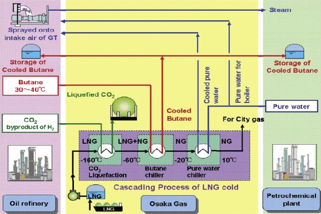
The cold energy users include an air separation plant, carbon dioxide liquefaction plant, propane and butane product chiller units, chilled water system, and gas turbine inlet air chiller. The system uses an intermediate fluid to transfer the cold energy from LNG to the different users in the industrial complex. The chilled water system is an effective method for distributing the cold energy to the processing units in the petrochemical plant and oil refinery. With a low-temperature chilled water supply, fractionation can be more effective and product yields and purities can be increased, consequently reducing the energy consumption and emissions from the integrated complex.
LNG wobbe index
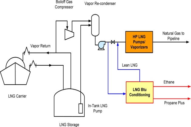
LNG import terminals typically receive LNG from different parts of the world and sometimes on a spot-market basis. The hydrocarbon content can vary depending on the gas fields and whether there is an upstream NGL recovery unit. As discussed in the section on LNG Quality and Gas Interchangeability in Chapter 1, the heating value and Wobbe Index of the LNG can vary widely, which may exceed the Wobbe Index specification of some countries, such as the United States and United Kingdom.
The most common method to reduce the Btu value of a gas is by diluting the vaporized LNG with nitrogen, up to the pipeline limit for inert content, usually 2 to 3 %. Nitrogen is an effective diluent for lowering the heating value and Wobbe Index, but would require the investment of a nitrogen plant, either a membrane type or a cryogenic separation type, which would not add any revenues to the facility. In addition, if the LNG supply is very rich, nitrogen dilution may exceed the maximum 3 mole % inert limit for pipeline gas.
Read also: Liquefied Natural Gas Plant and Regasification Terminal Operations
As an alternate to nitrogen injection, an LNG Btu conditioning unit can be installed that can be integrated to the LNG regasification plant as depicted in Figure 14. The conditioning unit can remove ethane and all the propane and heavier components from the LNG such that a lean LNG can be produced. The conditioning unit utilizes the cold energy from LNG for fractionation, and only a slip stream is required due to the high LPG removal efficiency. The LNG conditioning unit can also be designed for ethane products for a petrochemical plant. The blended LNG stream is further pumped and heated by LNG vaporizers to meet pipeline specifications. Since the LNG is leaner and is at a higher temperature, lower vaporization duty is required.
There are many patented processes that can be used to remove ethane and LPG components in an LNG terminal using LNG cold. One of the processes is the Fluor LNG Btu conditioning process shown in Figure 15. In this process, the LNG cold energy is used for cooling and refluxing the demethanizer and deethanizer. In addition, LNG refrigeration is also used for reliquefaction of the demethanizer overhead gas, which allows the liquid to be pumped to the pipeline pressure, eliminating gas compression equipment.

The Fluor process can recover over 97 % of the propane and 70 % of the ethane from LNG, pro-ducing a lean gas with a lower Wobbe Index, as shown in Table 4. The design feature of the Fluor process is the feed exchanger, E-1, which consists of two heat exchanger passes. The first heat exchanger pass uses the inlet LNG to cool and condense the lean residue gas from the demethanizer reflux drum. The second pass uses the residual cold to partially condense the demethanizer overhead to produce a lean, methane-rich reflux to the demethanizer column.
LNG refrigeration is also used to provide column reflux to the deethanizer. With lower overhead temperature, the deethanizer can operate at a lower pressure than conventional design. Consequently, less reboiler duty and smaller column size are required due to the more efficient separation process. The deethanizer produces an ethane overhead product and an LPG bottom product.
As shown in Table 4, with a rich LNG as feed, this process can produce 40,700 BPD of LPG product, 31,200 BPD of ethane, and 1,094 MMscfd of 1,021 Btu/SCF HHV pipeline gas.
LNG and CNG vehicle fuel production
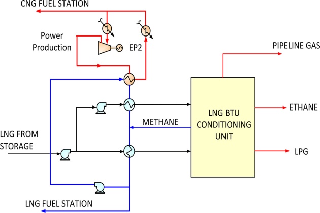
With the increasing higher oil prices, the use of LNG as transportation fuel is becoming economically attractive. Most terminals today have incorporated vehicle fuel stations for distribution of natural gas as LNG fuel or CNG fuel.
However, the presence of ethane and heavier components in LNG limits its use as a vehicle fuel, as most LNG is too rich to meet the vehicle fuel specifications. For vehicle fuel, a methane number of 80 is required for engine performance, which would require most of the nonmethane components to be removed. Figure 16 shows the configuration that can be used to coproduce vehicle grade LNG and CNG. LNG and CNG can be produced at the required pressure for the fuel filling stations. In addition, a cryogenic power generation facility using an expander cycle (EP2) can be incorporated in the design to supply power to the facility.
Based on the rich LNG feed, this integrated plant can potentially produce about 200,000 gallons per day of vehicle fuel quality, 51,000 barrel per day of LPG, and 59 MMscfd of ethane as shown in Table 5.
Integrated LNG regasification/power generation
The integration of an Process of Liquefied Natural Gas regasificationLNG regasification terminal with a power plant can significantly increase the power output and efficiency of power production while eliminating the heating requirement of an LNG facility. A conceptual design of an integrated plant is depicted in Figure 17.
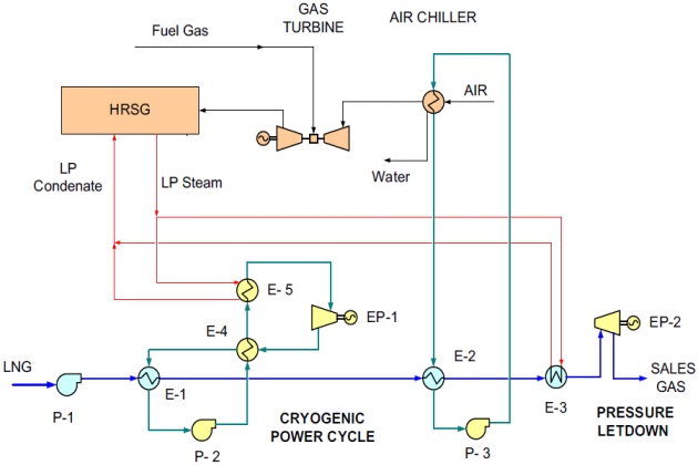
In this integrated plant, power is produced in three processes:
- Cryogenic power cycle;
- Pressure letdown from the vaporized LNG;
- Power increase from gas turbine inlet air cooling.
LNG cold is first used as a cold heat sink in power generation in an organic Rankine cycle using propane, butane, or mixed fluid as the working fluid. The working fluid is condensed in exchanger E-1, pumped by working fluid pump P-2 to a higher pressure, heat exchanged with the expanded working fluid in E-4, and further heated in E-5 to a higher temperature using low pressure steam from the power plant. Power is produced by expanding the high pressure working fluid to a lower pressure in EP-1.
LNG exiting from the cryogenic power cycle is further utilized in exchanger E-2 for gas turbine inlet air chilling. The LNG cold is transferred to the gas turbine inlet using a heat transfer fluid such as ethylene glycol water mixture. The cold glycol from E-2 is pumped by glycol pump P-3 and heat exchanged with inlet air to the gas turbine. When ambient air is chilled to 40 °F, almost all of its moisture content is condensed, and the air density is increased. The mass flow to gas turbine can then be increased resulting in a higher power output and efficiency. The condensate can be used as boiler feed water makeup to the power plant. The impact of lower gas turbine inlet temperatures on the gas turbine performance are further discussed in an earlier section.
Typically, a LNG high pressure pump is designed to deliver gas at 1 500 psig or higher, while the fuel gas pressure requirement in most power plant facilities is about 400 psig. The sendout gas can be heated to a higher temperature using waste heat and expanded with a second expander EP-2 to produce more power. Low pressure steam from the power plant can be used for heating. The expanded gas is then sent directly to the sales gas pipeline.
Availability of waste heat to the LNG regasification facility and cooling to the power plant must be considered in an integrated facility. The variations in power demand and sales gas demand must be evaluated to ensure both plants can operate independently from each other. This will require back-up facilities such as duct firing in gas turbines and a seawater vaporizer or SCV as backup system in the integrated facility.
LNG ambient air vaporizer
Ambient air vaporizers (AAV) are well known and are used in many cryogenic liquid plants to vaporize cryogenic liquids, such as liquid nitrogen. Typically, AAV heating duty is relatively small in these plants, which are not a limiting factor for the plot plan. On the other hand, the application to a base load LNG regasification facility is more difficult. The large heating duty would require a large number of AAV units and a large plot space, which makes the AAV option very expensive. For this reason, most of the existing regasification facilities use seawater or fuel gas for heating. However, with the environmental concerns on emissions from submerged combustion vaporizers and the problems associated with cold water discharge from seawater vaporizers, AAV is considered more environmentally friendly and is preferred in permitting.
AAV typically includes a number of individual multifinned heat transfer elements in serial or parallel configurations. Such a finned heat exchanger operation is limited by the ice buildup on the exchanger surface, which lowers the heat transfer coefficient. The LNG heating process must be stopped periodically and placed on the deicing cycle. To avoid cold air recirculation, the AAV must also be adequately separated, typically about 5 to 6 ft. The large number of AAVs and the plot requirement for a base load plant are very costly.
In the AAV design, deicing is done by natural draft convection, which is very slow. To reduce deicing time, force draft air fans may be used. However, such an operation reduces the defrosting time only marginally since heat transfer is still limited by the ice layer that acts as an insulator. To circumvent this problem, Fluor has developed a design method (patent pending) that uses a slip stream of the pipeline gas for heating the AAV that is placed on standby mode, as shown in Figure 18.
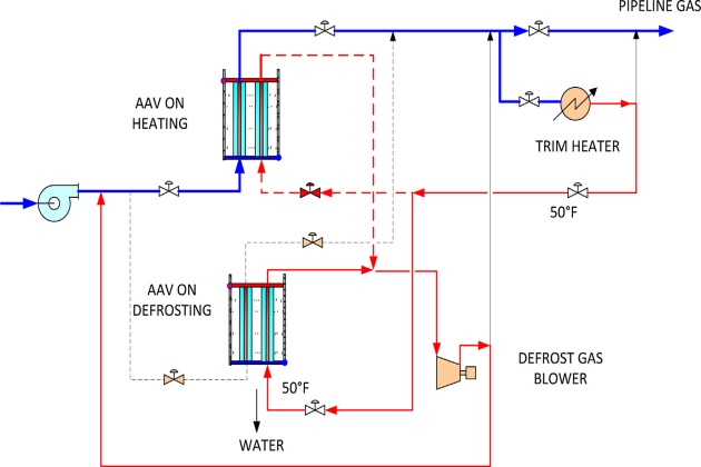
In the Fluor proposed design, a small blower is used to direct the pipeline gas to the bottom of the standby AAV. The hot gas will melt the ice on the inside of the exchangers, which will fall freely into the basin below by gravity. This hot gas deicing method can almost eliminate the standby time, and consequently can reduce the number of AAVs required. Consequently the plot space requirement for the AAV is reduced, improving the viability of the AAV economics.
LNG new berthing designs: jetties and subsea pipelines
The LNG terminal cost of service can be reduced by using a subsea transfer pipeline in lieu of a traditional jetty, which also offers the opportunity to save dredging costs as well as the cost of a jetty.
This part of the facility represents a major portion of the overall capital costs when one considers dredging, jetty construction, and process piping costs. The environmental impact of any required dredging is also a consideration. The LNG berth and jetty is required for the unloading of tankers. For locations with sufficient deep water access close to the coast, terminals may consist of jetty structures and breakwaters, where tankers can be moored and offloading can take place via the standard loading arms. Many locations require channel dredging and berth dredging to obtain the required water depths at berth and in the turning basin.
As an alternate to the trestle supported piping, subsea pipelines may be considered. A subsea pipeline can be used to transport the LNG to and from an offshore terminal, thereby eliminating the need and cost for a connecting trestle. With current subsea cryogenic pipeline designs, LNG can be efficiently transferred over distances of up to 20 miles. Buried subsea pipelines that have the proper designed cover are inherently safer from leaks and damage than exposed pipes. In addition, having buried cryogenic piping may improve the thermal performance of the pipeline in hot climates. By adding features such as real time monitoring of the performance of the pipeline for structural integrity, thermal performance and leaks using fiber optic technology, the safety of the subsea pipeline can be further enhanced.
Subsea cryogenic pipelines are emerging technologies that are essential for the new generation of offshore LNG loading and receiving terminals. A major issue for these systems is the pipe contraction due to the low temperature of the LNG. At present, there are mainly two methods to accommodate this contraction:
- Use of Invar or other alloys with an ultra-low thermal expansion coefficient;
- Use of bellows, one in each segment (about 50 ft long) of the pipeline, which is a self-contained pipe-in-pipe segment with vacuum insulation.
Although technically feasible, both methods suffer major disadvantages in cost, reliability, dura-bility, or maintenance requirement.
A new pipeline configuration (Patent Pending) has been developed to address these disadvantages. The configuration is the culmination of Fluor conceptual designs, which began in the 1970s with the design of a subsea LPG pipeline and continued into the 1980s with their first subsea LNG pipeline for an arctic LNG ship system. This new design, however, takes advantages of recent developments in insulation technology and uses a highly efficient thermal nano-porous insulation in the annular space between the inner and outer pipes (see Figure 19).
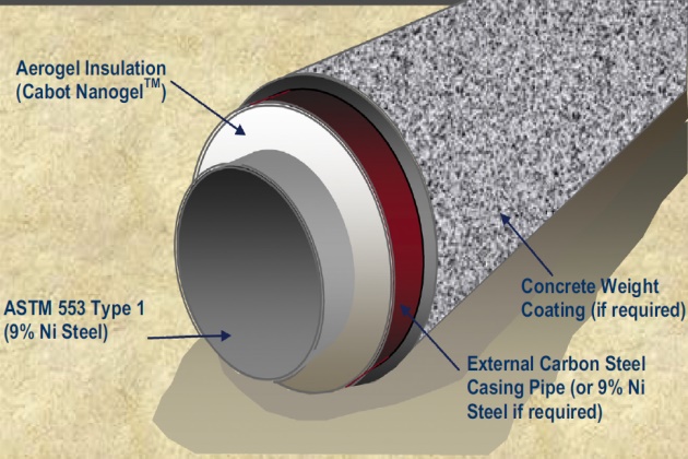
This material is kept in an ambient pressure environment, which is produced by sealing metal or nonmetal bulkheads. The bulkheads transfer the contraction induced axial tension load on the inner cryogenic carrier pipe(s) to the external jacket pipe. The resulting pipeline bundle is a structural element, which accommodates the thermal contraction and expansion loads without resorting to expansion bellows or ultra-low thermal expansion alloys. As an example, the LNG carrier pipe would be 9 % nickel steel, while the jacket pipe can be of carbon steel. The thermal insulation would be a high-performance nano-porous aerogel product, approximately 2 thick, in blanket or bead form installed within the annular space without vacuum and under ambient pressure.
Offshore loading and unloading hose
Open sea offloading of LNG cargoes to off-take carriers has been performed in a side-by-side configuration under benign environmental conditions. But because of potentially harsh sea environ-ments, the ship-to-ship transfer of LNG must be done in a tandem offloading configuration.
SBM Offshore has achieved certification for its Cryogenic Offshore Offloading and Loading (COOL) offshore LNG transfer system as well as qualification of the manufacturing process for the COOL hose and its connectors. The COOL system comprises a flexible cryogenic floating LNG hose and connectors designed to allow the transfer of LNG between vessels in a tandem mooring configuration.
The SBM hose design is based on a patented system, and comprises a well-proven outer marine hose with an inner composite LNG hose. The space between these two hoses is filled with insulating materials with excellent properties over the full range of ambient to cryogenic temperatures. The connector consists of both a structural and a fluid connector. It is a cryogenic quick connect/disconnect system that handles and connects the hose to the LNG carrier bow manifold and therefore facilitates LNG loading and unloading.