Unlock the full potential of Loran-C navigation with our in-depth guide. Discover key strategies for bias corrections, effective route planning, and practical tips to improve your navigation accuracy and confidence on the water.
- Introduction
- TDs Versus Latitude/Longitude: Reprise
- Bias Corrections
- Practice Often and in Good Weather
- Maintain a DR Plot and Cross-Check Fixes
- Exploiting Partial Information
- Use of the Route Function
- Cycle Stepping
- Plan Courses and Waypoints Considering Loran-C Accuracy
- Preplan Dockside and Cross-Check Data Entry
This article draws upon the material presented in other articles as a foundation for practical advice on the use of the Loran-C system.
Introduction
It presents additional information on the choice of coordinate systems, use of “bias” or “home port” corrections, use of Loran-C for HHA navigation, maintenance of navigation and performance logs, waypoint navigation, route selection and routing, and operation in fringe areas. Technical material is included, in this as well as other articles, to impart “know why” as well as “know how.”
As with Loran-C Receiver Features and Their Use“Understanding Loran Receivers: Features and Functionality”, the emphasis in this article is on marine users. Additional comments relevant to aviation users are also included.
TDs Versus Latitude/Longitude: Reprise
As noted in Loran-C Receiver Features and Their Use“Understanding Loran Receivers: Features and Functionality”, current marine Loran-C receivers have a coordinate conversion capability, so that either TDs or latitude and longitude can be used without having to refer to nautical charts for conversion. The use of the latitude and longitude coordinate system is familiar to most navigators, and many sources (e. g., the Light List and the US Coast Pilot) report the coordinates of navigationally important objects only in this coordinate system.
For this reason, many navigators prefer to use latitude and longitude exclusively. Provided that the mariner is prepared to accept the stated absolute accuracy of the Loran-C system or operates in waters where the absolute accuracy is greater than the system specification, there is nothing wrong with this practice. Indeed, this is undoubtedly how many mariners (and all aviators) use loran on a day-to-day basis. Nonetheless, there are some instances when greater accuracy – tens rather than potentially hundreds of yards – may be necessary or appropriate for safe passage. In these circumstances, TDs are to be preferred rather than latitude and longitude for marine applications. Guidance is offered below.
The process of automatic conversion from TDs to latitude and longitude is discussed in earlier articles. Basically this involves the use of mathematical models (imbedded in the loran receiver’s logic) for estimating the latitude and longitude corresponding to an observed set of TDs. This model includes allowance for PF, SF, and ASFs (refer to The Loran-C System: A More Detailed View“Understanding Loran Transmitters and Hyperbolic Systems”) on most receivers. As noted in Loran-C Position Determination and Accuracy“LORAN-C System: Accuracy and Position Determination”, however, there is presently no industry standard for this conversion process (though one is reportedly under development), and some receivers are much better than others in this regard. For applications requiring the greatest navigational accuracy, TDs are to be preferred to latitude and longitude. This section provides additional detail on this important topic.
The reader might be puzzled at the advice to use TDs in preference to latitude and longitude. Specifically, the reader might pose the following question:
I understand that the latitude and longitude of a position as calculated by the receiver might be in error (compared to “ground truth” or the vessel’s true geographic position), but if I use the same receiver toreturn to the same indicated position (in latitude and longitude coordinates) wouldn’t I be exploiting therepeat- able accuracy.of the system regardless of the coordinate system used? And if the loran is always used so as to take advantage of its repeatable accuracy, what is the reason for preferring one system of coordinates over another?
These are astute questions and deserve a careful answer. To begin, note that the receiver measures a set of TDs, and then calculates a latitude and longitude from these measured TDs using the ASFs stored in the memory (assuming that the receiver is programmed to include ASFs, as most are, and that the Auto ASF function is in use). Provided that the vessel (equipped with the same loran receiver) returns to a spot with the same indicated TDs (and is using the same secondaries), it is indeed true (if the Auto ASF function is engaged) that the displayed latitude and longitude will also be approximately the same. In this event, it would be solely a matter of convenience which coordinate system were used for the purpose of returning to a presurveyed waypoint.
However, remember that the ASF corrections are not only a function of the indicated position, but also (refer to The Loran-C System: A More Detailed View“Understanding Loran Transmitters and Hyperbolic Systems”) a function of the chain and secondaries in use. If, for whatever reason, the receiver were tracking different secondaries on the second visit, the ASFs would also be different, and so would the calculated latitude and longitude of a specific position. The problem arises if the assumption of the same rates is in error (Brogdon, 1991) – recall that receivers will sometimes use different secondaries at the same position (depending upon, inter alia, the respective signal strengths of the received signals from the various secondaries). Assuming that the same receiver is used, it is only if the same chain, the same secondaries, and the same ASFs are also used, that the mariner can assume that the latitude and longitude will be within the repeatable accuracy of the Loran-C system.
Moreover, there are two other circumstances where the correspondence between latitude and longitude and TDs will differ. Suppose first that the Auto ASF function is not enabled in the receiver. In this event, no ASFs will be applied to the observed TDs, and the latitude and longitude will differ from that determined if the ASF corrections were in use. Second, the mariner may be using a “home port,” “bias,” or “offset” correction (explained below) which also effectively alters the ASFs applied. In this instance as well, the correspondence between TD and latitude/longitude will be changed. Of course, the indicated latitude and longitude would also be slightly different if another receiver with different ASFs were used. For this reason, published waypoints are typically given in TD, rather than latitude and longitude, coordinates.
It is important to note that most loran receivers store waypoints in memory as latitude and longitude coordinates regardless of how these coordinates were actually entered into the receiver. In the process of storing these coordinates, ASFs then in use will be applied to the TDs to calculate the latitude and longitude to be stored in the receiver’s memory. If on a later visit, the same ASFs are applied to the same TDs, the latitude and longitude will also be the same. If, however, the Auto ASF is disabled or another chain and/or secondaries are in use, the positions may differ. Normally these differences will be small and within the published absolute accuracy of the system, but could nonetheless be substantially less accurate than the repeatable accuracy of this system.
The simplest way to deal with this situation (Brogdon, 1991) is to record the observed TDs corresponding to any waypoint of interest. In particular, it is useful to record all TDs – not just the two TDs in use Recall, however, that some receivers use more than two TDs to determine a position.x – so that, on a later visit, if the preferred secondaries are unavailable or unusable, the mariner can still find the waypoint using other TDs. When using the loran in navigation mode – i. e., when navigating to a waypoint using range and bearing information, the user should be careful to check that the same secondaries are in use and that the ASF correction function in use is the same as when the waypoint was originally entered in memory. Otherwise the accuracy of the system will be degraded.
Another aspect of ASFs and latitude/longitude conversion that should be noted is the receiver’s ASF logic when using the loran in a planning mode. The receiver can be used to convert the coordinates of a waypoint from latitude/longitude to TDs. In principle, the receiver should use the ASFs appropriate to the latitude and longitude of each waypoint for this conversion. However, published reports (Jones, 1989), indicate that at least one well-known receiver uses the ASFs corresponding to the vessel’s current position and not the ASFs corresponding to the actual waypoint location for the conversion.
This difference could be of little consequence if the waypoint were close to the vessel’s location, but could be quite significant if the waypoint were a long distance away. This difficulty is not inherent in the Loran-C system, but rather an artifact of the software used in at least one particular make. Incidentally, this peculiar feature was not covered in the owner’s manual. In the case related by Jones, the waypoints being converted were along the Maine coast and the vessel’s location at the time of conversion was in Massachusetts. Because ASFs change appreciably in this region, the converted positions were up to 0,5 miles in error – a figure in excess of the absolute accuracy specifications of the system. The point of this illustrationis that the user should become familiar with the specific features of the particular loran. Although Jones (1989) raised this point in connection with only one make and model of receiver, the above point is more general.
Whether or not the gain in accuracy achieved by using TDs or bias corrections (see below) is worth the effort depends very much upon the circumstances. Finding a fairway buoy marking the approximate centerline a “wide“ The word “wide” is put in quotation marks to indicate that it may have different meanings for different classes of vessels. The effective width of a “channel” would be substantially different for a tanker drawing 30 ft of water than a sailing vessel drawing 6 ft or a jet drive vessel drawing 1 ft.x channel in excellent visibility does not require pinpoint accuracy, nor are the consequences great if this buoy is missed. However, finding a lateral buoy marking the edge of a narrow channel with surrounding hazards on a fog – shrouded day requires very careful navigation and operation of the Loran-C receiver so as to maximize accuracy.
Bias Corrections
Most modem Loran-C receiver can accommodate ASF corrections in two ways. The Auto ASF function can be enabled or disabled. That is, prestored ASFs can be included or excluded. Most Loran-C receivers also have an additional feature, variously called a “bias,” “offset,” or “home port” correction by receiver manufacturers. To use this feature, the mariner travels to an accurately known location – often a dock at the marina – and manually enters these known coordinates into the loran, either directly, or as differences (called “deltas” in some owner’s manuals) or offsets to the known latitude and longitude. In this way, the observed position (in latitude and longitude coordinates) error will be forced to equal zero at this location.
This seems a simple and elegant way of “calibrating” the receiver in the local area and increasing the accuracy of the latitude and longitude readouts. Useful as this procedure is, the mariner should be aware of some limitations of this technique. In effect, the user is entering an “ASF-like” correction into the receiver’s memory toreplace (or supplement) the presto red values For example, there are several marinas located along the Delaware River in close proximity to bridges and one located directly under the Ben Franklin Bridge in Philadelphia, PA. A home port correction developed in this location could be seriously in error outside the zone of influence of the bridge.x. At best, this correction includes all the factors normally considered in ASF corrections, but also reflects a compensation for season, diurnal, and secular trends in signal propagation. In effect this represents a crude differential Loran-C adjustment. However, this correction is only exact for the particular calibration point used, and not necessarily for other, more distant, locations. Were this procedure repeated in another location, the correction would be slightly different.
Within what range is this “local area correction” valid? Table 1 provides a sampling of published estimates, ranging from approximately 10 miles to 100 miles from the point of calibration. Although these values are given for perspective, the mariner should determine empirically the limits in waters frequently cruised. The mariner should also give some consideration to the calibration point.
| Table 1. Approximate limits of applicability of “Home Port” or “Bias Corrections” as given by various sources | |
|---|---|
| Maximum Distance From Original Reference Point Where “Home Port” Correction is Applicable (NM) | Source |
| 10 | Practical Sailor, 1990 |
| 10 | Marinteck Owner’s Manual |
| 20 | Melton, 1986 |
| 25 | Voyager Loran-C Owner’s Manual |
| “Fairly Broad Area” | Raynav 570 Owner’s Manual |
| 100 | Gait, 1990 |
| 100 | Dutton’s Thirteenth Edition |
| Remember, these are only estimates, designed to be representative over a broad area. Mariners are cautioned to verify these estimates for frequently traveled waters. | |
For example, the mariner’s home port could be a marina neara metal bridge, overhead power lines, or other natural or man-made obstructions. In this event, the home port correction might be quite inappropriate for locations only a few hundred yards away For example, there are several marinas located along the Delaware River in close proximity to bridges and one located directly under the Ben Franklin Bridge in Philadelphia, PA. A home port correction developed in this location could be seriously in error outside the zone of influence of the bridge.x.
Even if the mariner’s home port is not affected by anomalies caused by bridges, powerlines, or other objects that produce localized distortions in the loran grid, the areal extent over which this bias correction is applicable is a function of how much the ASFs vary over the region of interest. And, as even acasual examination of DMAHTC’s ASF tables will show, the variation in ASF can differ significantly, depending upon the chain, secondary, and location. Therefore, none of the estimates given in Table 1 should be accepted uncritically.
Those who elect to use an offset correction should also be aware that the entry of this correction effectively alters the apparent locations of any waypoints stored prior to establishing this home port correction. Finally, users should refer to the owner’s manual fordirections on how to enter this correction and for other relevant particulars. For example, on some lorans, the home port correction is automatically deleted if the set is turned off, on others, the correction is retained in memory until it is deliberately erased.
Even if the vessel remains in the same waters, there is some benefit to reentering home port corrections from time to time. Recall from material presented in Loran-C Position Determination and Accuracy“LORAN-C System: Accuracy and Position Determination” that TDs have seasonal, diurnal, weather-related, and possibly secular components. Periodic recalibration can, in principle, remove some of this variability and increase accuracy in a local area.
If the vessel strays from the local area, the bias should be changed when the opportunity pesentsitself for an accurate fix. DePree (1987), for example, claims that daily site-specific bias corrections enabled Loran-C position accuracies of 0,5 miles or better when cruising in the Bahamas. This area is not included in the coverage diagrams for the 7980 chain, and uncorrected fix errors of five miles or more are common in these same waters. This “poor man’s dynamic differential Loran-C” is sound in principle, but the mariner should allow an extra safety margin when entering waypoints to guard against the possibility of degraded accuracy. Moreover, every opportunity should be taken to verify Loran-C position information by other means – a point emphasized below and throughout this Loran-C Handbook. The United States Coast Guard does not encourage the sole use of any one navigation system in any potentially hazardous waters, much less when operating in areas outside the defined coverage area of a navigational system.
Finally, the mariner should be aware that a bias or home port correction will cease to be appropriate if the loran receiver switches secondaries or chains. May (1987) recounts just such an experiencewhich occurred off Monomoy Island near Cape Cod, MA. According to this account, the vessel operator just happened to be looking at the loran when it switched secondaries This probably occurred because the vessel was in the vicinity of the Xray baseline extension of the NEUS (9960) chain.x and noticed that the indicated position “jumped” out of the channel and moved to a nearby shoal! The mariner had entered a bias correction which was no longer appropriate when the receiver changed secondaries.
There are two lessons to be learned from this cautionary tale. First, bias corrections should not be used in or near areas where chain or secondary switches may occur – such as in the vicinity of a baseline extension. The second lesson to be learned is that the mariner should systematically record the secondaries in use whenever a fix is taken (see below). May’s account does not mention that this procedure was used – rather, it gives the impression that the observation of a rate switch was entirely fortuitous. If, however, the mariner noted the rates in use whenever a fix was recorded, the rate switch would have been detected and the bias correction could have been removed.
Practice Often and in Good Weather
Mariners should become thoroughly familiar with the operation and performance characteristics of their loran receivers. The best way to ensure the required familiarity is by frequent practice. As noted in other articles, loran manuals are not always well written, and many loran sets have idiosyncracies that are not thoroughly documented in the owner’s manual. The only way to learn about a particular receiver is to practice in “benign” conditions (e. g., in good weather and in an area relatively free of hazards to navigation) when errors are not critical, and there is time to read (and reread) the owner’s manual while underway. This practice can be put to good use when weather or other conditions deteriorate and there is no time for such a deliberate approach.
Part of the reason for this practice is to become familiar with the purely “mechanical” aspects of operation of the loran receiver. But another important reason is to gather useful data on such elements as loran accuracy (both repeatable and absolute), typical SNRs, waypoint coordinates, etc., in areas frequently traveled. The material on these topics in this Loran-C Handbook is as complete as possible, but cannot reflect all relevant site-specific information. For example, SNRs measured at the receiver are a function of the distance from the various transmitters (as noted in Loran-C Position Determination and Accuracy“LORAN-C System: Accuracy and Position Determination”). In principle, these distances could be used to calculate contours of constant SNR on generalized charts. But SNRs are also a function of the receiver make and model, adequacy of grounding (see Installation and Related Matters of Loran-C“Complete Guide to Loran-C Installation and Related Matters”), local interference aboard ship, receiver placement on the vessel, weather, and other factors that cannot easily be generalized or presented as “typical” values.
Therefore, it makes sense for the vessel operator to maintain a “performance log” which summarizes these data for the particular installation. Even a procedure as simple as noting in a performance log the SNRs of the various TDs when the vessel is tied at the dock can be useful. Figure 1 shows such data in the form of a statistical control chart Readers unfamiliar with statistical control charts will find details in any elementary textbook on statistical quality control, for example, Duncan, A. J. Quality Control and Industrial Statistics, Third Ed., Richard D. Irwin, Homewood, IL, 1972, or Grant, E. L., Statistical Quality Control, Third Ed., McGraw-Hill Book Company, New York, NY, 1964.x for the Yankee secondary of the NEUS (996) chain for 22 days during the summer of 1991. Data plotted are in units of the two-digit SNR codes displayed by the receiver, rather than the actual SNR.
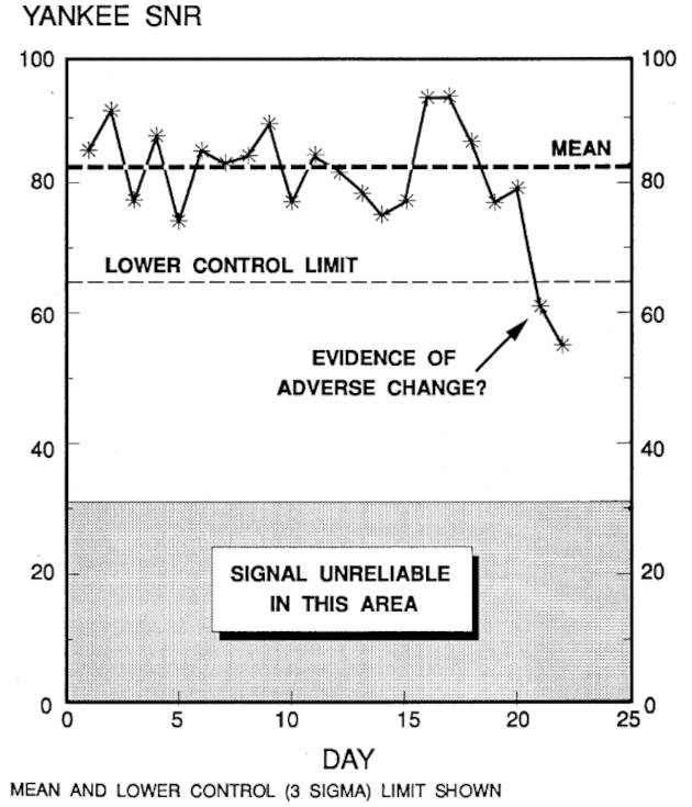
These data were taken with a hand-held loran receiver (without an external ground) on an aluminum patrol facility in the upper Delaware River, docked at a fixed Search and Rescue Detachment (SARDET). The dashed line in this figure represents the average of the SNR readings of the Yankee secondary over the first 20 of the 22 days, and the dotted line the lower control limit. Although statistical techniques beyond the scope of this handbook were used to compute the lower control limit, it should be clear from visual inspection of the plot given in Figure 1 that “something happened” after day 20 in the sequence. Note that the SNR exceeded the manufacturer’s minimum SNR for reliable signal reception (denoted by the shaded area in Figure 1) throughout this period, but the trend evident in these data points to some adverse development that should be investigated. Such a drop in SNR could have been caused by a failed alternator filter, the installation of new equipment aboard the vessel, weather in the last 2 days or other factors – see Installation and Related Matters of Loran-C“Complete Guide to Loran-C Installation and Related Matters” – but the point of this example is that these data can be used to advantage.
Entries in the performance log should indicate the vessel’s position, SNR, an accuracy measure (if provided by the receiver), known weather (e. g., a thunderstorm at the location), a listing of the status indications or alarms at the time, and a list of other electronics (e. g., radar, depth sounder) in operation. The important thing is to record these data systematically so that performance norms can be established. Later, actual readings can be compared with these performance norms to detect anomalous conditions and begin a search for an “assignable cause.” For ease of exposition, the performance graph shown in Figure 1 was deliberately simplified. In practice, SNRs from the master and all usable secondaries would be recorded and plotted, not just data for the Yankee secondary.
Yet another reason for noting SNR measurements is to help detect “cycle slips” that can occur in fringe areas, high noise environments, or if the receiver is not installed properly (see Doyle, 1986). In these circumstances, the receiver may fail to track the appropriate point (3rd positive zero crossing in the pulse, see The Loran-C System: A More Detailed View“Understanding Loran Transmitters and Hyperbolic Systems”) and instead track another zero crossing which differs by an integer multiple of 10 usec (e. g., 10 usec, 20 usec, 30 usec) from the correct tracking point. If this occurs, the measured TD(s) (and thus the vessel’s apparent position) would be in error by an equivalent amount. Therefore, it is important to detect this condition should it occur.
Most receivers are programmed to automatically detect (normally by comparing the amplitude ratio of the peaks on either side of the tracking point), display (via a cycle alarm or status indicator), and ultimately correct this condition. For most (but not all) makes and models these alarms and status indicators work well. However, the user should also be alert to the potential for this problem to arise – particularly in fringe areas or in other circumstances where cycle slip is more likely. It is mentioned in this context because when cycle slip occurs, so too does the SNR. Referring to the pulse envelope shape discussed in The Loran-C System: A More Detailed View“Understanding Loran Transmitters and Hyperbolic Systems”, note that the signal amplitude increases as the tracking point is “slipped” further into the pulse. Cycle slips, therefore, will be associated with a change in the SNR of the received signal. Other methods for detecting these slips are reviewed below. If the mariner systematically records the SNR when the vessel’s position is fixed, cycle slips may be evident in changes from these preestablished norms. SNR measurements can also be used to determine if a secondary is “off-the-air.”
Practice sessions with the loran can also be used to record the coordinates of desired waypoints (entered in the receiver and in a separate waypoint log) so that the loran’s repeatable accuracy can be used when in “instrument” conditions. The vessel operator can practice “blind” approaches (of course with competent lookouts aboard to avoid collisions and ensure that the vessel does not stray from safe water) to key harbors or anchorages to gain familiarity with the waypoint sequencing options and confidence in the capability of the loran system. The mariner might also wish to evaluate the utility of “home port” corrections (discussed above) and the likely accuracy to be attained with these corrections.
Maintain a DR Plot and Cross-Check Fixes
It is physically possible to navigate a vessel entirely by electronic means, but this is not a prudent course of action. In particular, navigators should never abandon the practice of maintaining a DR plot. Methods and graphical conventions for construction of a DR plot are beyond the scope of this handbook, but can be found in any text on coastal piloting or navigation. Absent sophisticated interfaces between the loran, fluxgate compass, and a speed sensor, the only way the navigator can estimate the set and drift of the current is by comparing the vessel’s DR position with a contemporaneous fix. Therefore, one major purpose of the DR plot is to enable estimation of set and drift – and derivatively determining a course to steer to compensate for the current.
Another purpose of the use of the DR plot is to provide at least a gross “reality check” on the positions determined by the loran. Figure 2 illustrates how this might be done. The figure itself shows the DR plot, estimated position after one hour, intended track and loran fix. The inset shows a stylized replica of the loran display at the time of the fix.
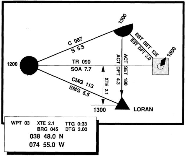
In this example, a mariner estimates the current set and drift to be 135 degrees and 3,0 knots respectively. Assuming a speed through the water of 5,5 knots and a desired track of 090 degrees to the waypoint indicated by the buoy, the navigator determines that an appropriate course to steer would be 067 degrees, and that the estimated speed of advance would be approximately 7,7 knots. After one hour in this example (in actual practice fixes would be more frequent) the navigator notes the loran fix (denoted by the triangle in Figure 2) and calculates the actual set and drift to be 180 degrees and 4,3 knots respectively. The mariner can use this information to help assess the plausibility of the loran position. Cycle slip, for example, might be detected by this method. If cycle slip were suspected, several possible loran positions could be plotted by sequentially assuming that one or both of the TDs were +/- 10 usec in error. If any of these alternativepositions were much more consistent with the estimated set and drift, the hypothesis of cycle slip might be supported.
The navigator should also maintain a DR plot because the loran may become inoperative. As noted in Introduction and Overview of Loran-C“What is Loran-C? Exploring Its Role in Marine Radionavigation”, the Loran-C system availability is excellent – better than 99,7 % availability for any given triad. However, the availability of the onboard receiver may not attain these levels – particularly if it is subject to direct contact with seawater, varying input voltages, and other environmental challenges to reliable operation. A DR plot would be invaluable if the loran became inoperative.
Along with maintaining a DR plot, the navigator should establish a definite interval for recording fixes. The loran receiver is continually updating the vessel’s position (every few seconds or so), but the advice here is torecord the loran fixes in the voyage log or navigator’s workbook and to plot the fixes on the nautical chart. (Before the advent of coordinate converters, mariners had to plot the TDs to determine a position on the chart, but automatic converters eliminated this requirement.) The fix information should include the coordinates, secondaries in use, SNRs, and a notation describing any pertinent status indicators (e. g., SNR or cycle flags). Not only is this fix information necessary for computing current set and drift (from a comparison with the DR position) but also writing down and plotting the fix information could be quite useful in the event that the loran fails. The appropriate interval between fixes is a function of the vessel’s speed, frequency of course and/or speed changes, and the navigational hazards posed by the route. Appropriate fix intervals could range from every 3 minutes or so (for a fast moving vessel or one in a narrow channel) to once per hour for a sailboat or power vessel in the open waters well removed from HHAs.
Three practical ideas
- Always maintain a DR plot.
- Record Loran positions in a log according to a definite schedule.
- Verify Loran fixes using all other available methods.
Finally, the mariner should attempt to confirm any loran fix by other methods-particularly if the fix is “critical.” One obvious method for checking a fix is to note the water depth at the time of the fix. When the fix is plotted, the observed depth can be compared (after adjustment for the tide height if necessary) with the charted depth at the fix to verify the fix. Of course, if the water depth does not vary appreciably over a broad area, this validation method would not be useful. Visual bearings can also be taken in pilot waters, and buoys are also helpful inverifying positions. Certainly, spotting a buoy in the wrong position (Humber, 1991) ought to alert the navigator to the need for special vigilance.
Exploiting Partial Information
Normally, a loran receiver is either working satisfactorily or it is not. However, it sometimes happens (see Dahl, 1986 or Gait, 1990 for examples) that partial loran information is available. For example, the receiver may be able to display TDs, but the latitude/longitude conversion and navigation functions may be inoperative. Alternatively, only one TD may be available or usable. Although only one TD would not be sufficient to provide a fix, it does determine an LOP which could be crossed with a visual or RDF bearing or by some other means (e. g., a depth contour or a celestial sight) to determine a fix. Alternatively, depending upon the angle of the TD to the intended track, the TD might be “followed” to a point closer to the shore where visual bearings could be used. Obviously, limited infomation should be regarded with healthy suspicion, but should not be disregarded entirely.
Another example of the use of limited information is as follows. It frequently happens in the HHE/HHA phase of navigation that loran cannot be used as a primary navigation system (say because either absolute or repeatable accuracy is insufficient to navigate a narrow channel), but that loran information can be a valuable supplement. In the narrow channel example above, it may well be the case that loran could not be used to determine whether or not the vessel were in the channel, but the loran readout (in conjunction with the observed position in the channel) could be used to determine a fix. In essence visual observation would determine one coordinate of a fix, while the other coordinate would be supplied by the loran. Moreover, even in this circumstance the loran’s ground speed readout would be usable.
Use of the Route Function
As noted in Loran-C Receiver Features and Their Use“Understanding Loran Receivers: Features and Functionality”, many loran receivers have a route function that enables the navigator to link waypoints together into an overall route. Operating details vary by make and model of receiver, so these points are omitted here. Refer to the owner’s manual for this information. Waypoints used can be entered by actually visiting each and using the receiver’s “save” capability (this has the advantage of exploiting repeatable accuracy), entered directly as latitude/longitude or TDs, or selected from among the available waypoints previously stored in the receiver’s memory. Routes are stored in memory, as are waypoints, and must be planned with applicable memory limitations in mind.
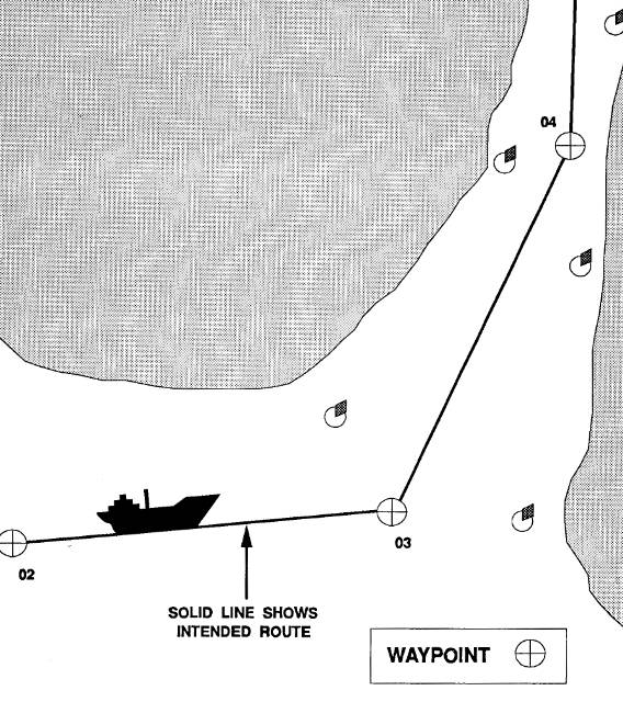
Usually, the waypoints in a route are arranged so that these correspond to points where thevessel’s course or speed needs to be changed. Figure 3 illustrates a route consisting of several waypoints (denoted by circles with crosshairs and a waypoint number in this diagram) for traversing a harbor entrance. If the channel were narrow, it might be necessary to have visited the waypoints earlier to ensure that the repeatable accuracy of the loran was attained. Of course, the same effect could be achieved by sequentially entering waypoints as the vessel proceeds along the route, but the advantage of using a route function is that the receiver will automatically switch from waypoint to waypoint as the vessel passes each in sequence. Moreover (see below), it is good practice to minimize the number of keystroke entries that have to be made while the vessel is underway.
It sometimes happens that the navigator wishes to by-pass any individual waypoint in the route sequence. Figure 4 illustrates this situation. The route originally planned consisted of the waypoints 02, 03, 04, 05, etc. But, after reaching waypoint 02, the mariner decides to travel directly from 02 to 04 (along the track indicated by the dotted line) rather than visiting waypoint 03 as programmed in the original route sequence. The route function of most receivers enables this to be done without having to enter in an entirely new sequence of waypoints – a handy feature. However, this feature must be used with care, and only after the navigator has determined that the direct leg between waypoint 02 and 04 (in this example) can be traversed safely.
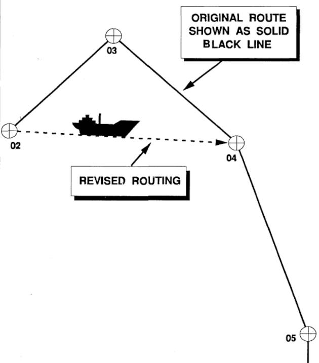
Remember, the loran receiver has no idea of the hazards to navigation or water depths along any route. There may, in fact, be an island between waypoints 02 and O4! It is the mariner’s responsibility to lay out each route on the nautical chart and assess whatever hazards lie along the route. Although this would almost seem too obvious a point to mention, groundings have occurred for this very reason. Automatic features are intended to facilitate navigation, not to eliminate the need for common sense.
In some cases a route may have been defined but, for one season or another, the navigator may have permitted the vessel to dnft off the intended track. The vessel operator has two choices:
- Steer a course to return to the original track;
- Or restart the route and travel directly to the next waypoint in sequence after “zeroing out” the cross-track error.
Most loran receivers enable the route to be restarted from any point, eliminating the need to return to the original track to obtain useful navigational information.
Most receivers with a route function enable any route stored in memory to be traversed in either direction. For example, a mariner departing a harbor in good weather can save waypoints along the way to define a route and merely run this route in reverse waypoint order to return safely to harbor.
Cycle Stepping
In The Loran-C System: A More Detailed View“Understanding Loran Transmitters and Hyperbolic Systems”, and elsewhere in this category, it is noted that the Loran-C receiver is programmed to track on the third positive zero crossing of the loran pulse – 30 usec into the pulse. This tracking point has been selected based upon an engineering compromise. On the one hand, the further into the pulse (on the leading edge) the sampling or tracking point is placed, the greater the signal strength – until a point approximately 60 usec from the start of the pulse. Therefore, setting the tracking point further into the pulse will (other things being equal) increase the SNR. On the other hand, “advancing” the tracking point increases the likelihood of skywave contamination – and consequently of incorrect TDs. The 30 usec tracking point strikes a practical compromise – the SNR at this point is sufficiently good for most navigational purposes, and the likelihood of skywave contamination is small.
However, navigators who venture into “fringe areas” – areas near the limits of Loran-C coverage – may find that the SNR at the normal tracking point is insufficient for reliable navigation. Popular cruising areas which could be termed “fringe areas” include the Bahamas, Bermuda, portions of the Gulf of Mexico, and the area south of San Diego, CA, on the West Coast, particularly the Baja Peninsula. Although skywave contamination is a threat, mariners who cruise in these fringe areas may wish to take a calculated risk and alter the tracking point in order to have a sufficiently strong signal for navigation. USCG cannot assume the responsibility for Loran-C fix accuracy if cycle-stepping is used.
Many receivers permit this tracking point to be altered by a technique known as cycle stepping. Simply put, cycle stepping advances the tracking point of the pulses received by the master and the secondaries so as to provide a greater SNR. Deliberate use of skywaves is another approach to navigation in fringe areas discussed in Use of Skywaves for Navigation“Harnessing Skywaves for Navigation With Loran-C”. Again, the owner’s manual for the specific make and model of receiver should be consulted for the specific “mechanical” steps (i. e., the sequence of buttons to push) necessary for cycle stepping.
The conceptual procedure for cycle stepping is straightforward. First, it is necessary to determine the vessel’s position as accurately as possible, noting the correct TDs (from a loran overprinted chart) corresponding to the vessel’s position. Second, it is necessary to disable the ATS function of the receiver and manually select the GRI and secondaries for use. Next, it is necessary to override the automatic tracking function. Once these three steps have been completed, the tracking point on the master and secondaries can be advanced (in 10 usec increments) until an acceptable SNR results.
Usually, the master signal is cycle stepped first (by, say, 10 usec or 20 usec), and then the secondaries are stepped the same number of cycles. If both the master and the two secondaries are advanced by the same number of cycles, the observed TDs will not be changed. Advancing only the master will decrease the measured TDs, while advancing only the secondaries will increase the measured TDs. If the master and the two secondaries are cycle stepped by the same amount, the vessel’s indicated position will return to the position originally noted, or to the vessel’s “actual” position (give or take the basic loran accuracy). If the master and secondaries are not stepped by the same amount, the difference must be applied as a correction to the observed TDs. For example, if the tracking point of the master were advanced by 20 usec, while those for the two secondaries were advanced by 10 usec, 10 usec would have to be added to each TD to determine the vessel’s correction position.
Users should bear in mind that the limits of loran coverage are calculated based upon both SNR and accuracy criteria. Operating outside the limits of the published coverage diagram not only increases SNR problems, but also operates the vessel in areas of decreased loran accuracy. Recall from Loran-C Position Determination and Accuracy“LORAN-C System: Accuracy and Position Determination” that the absolute (and repeatable) accuracy of the loran is a function of geometry (i. e., gradients and crossing angles). Areas of low SNR (for which cycle stepping may be required) are also likely to be areas of “poor” geometry where the accuracy of the system is degraded.
Cycle stepping may be appropriate if there is no viable alternative, but operation in areas of low SNR must be done cautiously – and with due allowance for the fact that accuracy may be considerably degraded or compromised by either geometry or skywave contamination. Obviously, positions so determined must be regarded with particular suspicion, and should be verified by all other available means.
Plan Courses and Waypoints Considering Loran-C Accuracy
As noted in many places in this document, the absolute accuracy of the Loran-C system within the defined areas of coverage is between approximately 0,1 and 0,25 nautical miles – repeatable accuracies are significantly better. One obvious consequence of these accuracy limitations is that courses should be planned with these limits in mind. Where possible, survey the waypoints to take advantage of the repeatable accuracy of the loran. If visiting an area for the first time, ensure that courses (and alarms) are set with due regard for the limitations of this system. In many cases this is quite easy to do, and amounts to nothing more than laying out courses and waypoints that provide an adequate margin of safety and allow the vessel to remain well clear of charted hazards to navigation. If this cannot be done, because the channels are too narrow or for other reasons, the loran should be assigned a supporting role, and other methods of position fixing (e. g., optical bearings and ranges, or radar) should be used as the primary means of navigation.
Arrival alarms (if utilized) should be set at a distance which enables the lookouts to have sufficient advance warning of an approaching waypoint in cases where this waypoint is a physical object, such as a buoy or light tower. Cross-track error alarms should be set if hazards to navigation require more precise navigation. But these alarms should be set with a safety margin to allow for Loran-C error.
Figure 5 illustrates this point. Here the waypoints, route, and cross-track error alarm distance are laid out so that the vessel will have ample clearance from the two shoal areas. The appropriate amount of safety margin is a matter ofjudgment, and should consider whether or not waypoints 04 and 05 are known to within the repeatable or absolute accuracy of the system.
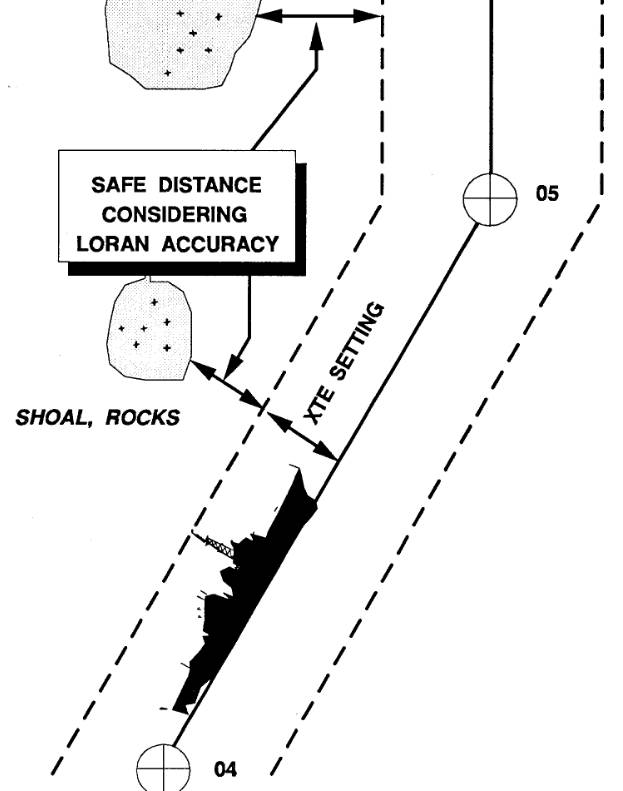
If physical constraints (e. g., shoals to the east) do not permit a sufficient safety margin, then use of buoys, range markers, danger bearings, radar fixes, etc., should be planned.
Preplan Dockside and Cross-Check Data Entry
Operator error accounts for the majority of accidents or incidents caused by faulty navigation. This holds true for use of all navigation systems, including loran. Human errors associated with loran use include conceptual errors, such as a failure to understand the accuracy limitations of the system or the use of bias corrections in an area far removed from the point of calibration, and operational errors, such as entering the wrong coordinates for a waypoint, and allowing this error to go undetected because of insufficient cross-checks among various navigational systems. Such errors underscore the need for constant vigilance in navigation. The following ideas may prove useful to reduce the likelihood or consequences of human error.
Entering data into a loran receiver (e. g., waypoint coordinates,routes, adjusting the ASF corrections, etc.) is much easier at dockside, when the vessel is not rolling or pitching and the operator is not distracted by other duties, than while underway. This is particularly important in small craft where the operator is also the navigator. Indeed, the vast majority of the data entry (aside from storing waypoints underway or switching “pages” in the receiver display) can be completed well before the mooring lines are cast off at the beginning of a voyage.
Where possible, have someone else cross-check data entries, such as waypoint coordinates. Often the person entering the data will miss certain types of errors (particularly transposition errors, as latitude 41 04,6 in place of latitude 41 40,6) that are more easily detected by a second person. Commercial aviators do this when loading coordinates into inertial navigation systems as a matter of routine – the co-pilot checks entries made by the captain. Distances and bearings from waypoint to waypoint taken from the nautical chart can be matched against the receiver display as an added check on data entries.
Carrying a second loran receiver (independently programmed) furnishes another check on he vessel’s position and also reduces the likelihood of both receiver’s being inoperative. Prices of lorans have fallen to levels so low that carrying a second receiver as a backup is a very cheap form of insurance. Carrying an entirely independent navigation receiver, such as GPS, would protect the mariner against system failures of either system. This would be a costly option given present prices for GPS receivers, but these prices will decrease in the future.

- Abramowitz, M., et al. “Approximate Method for RapidLoran Computation,” Navigation; Journal of the Institute of Navigation, Vol. 4, No. 1, March 1954, pp. 24-27.
- Alexander, G. “The Premier Racing Tool,” Ocean Navigator, Issue No. 20, Jul/Aug 1988, pp. 37, er seq.
- Anonymous. “Loran: Installation Pitfalls, and How Friendly Should Your Loran Be?” Practical Sailor, Vol. 11, No. 24, December 15, 1985, pp. 1, et seq.
- Anonymous. Manual on Radio Aids to Navigation, International Associationof Lighthouse Authorities, Nouvelle Adresse, 13 Rue Yvon-Villarceau 75 116, Paris, 1979.
- Appleyard, S. F. Marine Electronic Navigation. Routledge and Kegan Paul Ltd., Boston, MA, 02108, 1980.
- Ashwell, G. E., B. G. Pressey, and C. S. Fowler. The Measurement of the Phase Velocity of Ground Wave Propagation at low Frequencies Over a Land Path. Proceedings of the Institute of Electrical Engineering (London) 100 Part III, 1953.
- Bedford Institute of Oceanography. Loran-C Receiver Performance Tests, Bedford Institute of Oceanography, P. O. Box 1006, Dartmouth, NovaScotia, Canada, B2Y 4A2.
- Blizard, M. M. et al. Harbor Monitor System Final Report, CG-D-17-87, ADA 183 477, Dec. 1986, Available through the National Technical Information Service, Springfield, VA, 22161.
- Blizard, M. M., Lt. and CWO 3 D. C. Slagle. Differential Loran-C System Final litter, Draft, United States Coast Guard, January 1987.
- Blizard, M. M. and D. C. Slagle, “Loran-C West Coast Stability Study,” Proceedings of the Fourteenth Wild Goose Technical Symposium, Wild Goose Association, Bedford, MA, 1985.
- Brogdon, B., “Loran Expansion,” Ocean Navigator, Issue No. 42, SeptfOct 1991, pp. 87, et seq.
- Brogdon, W. “Loran Hook, a Little Known, Foible Explained,” Boating, August 1991, p.42.
- Brogdon, W. “Electronic Errors,” Ocean Navigator, Issue No. 40, June 1991,pp. 70, etseq.
- Brogdon, W. “Pathfinders,” American Hunter, Vol. 19, No. 7, July 1991.
- Burt, W. A., et al. Mathematical Considerations Pertaining to the Accuracy of Position, Location, and Navigation Systems, Part I, Stanford Research Institute, 1966. Available from National Technical Information Service, AD-629609, US Department of Commerce, 5825 Port Royal Road, Springfield, VA 2215 1.
- Canadian Coast Guard, Aids and Waterways Branch. A Primer on Loran-C, Ottowa, Ontario, Canada, 1981.
- Connes, K. The Loran, GPS & NAVICOMM Guide, Butterfield Press, 1990.
- Culver, C. “A New High Performance Loran Receiver,” Proceedings of the Sixteenth Annual Technical Symposium, The Wild Goose Association, 20-27 October 1987, pp. 282, et seq.
- Dahl, B. “Adopting Loran-C to Everyday Navigation,” Cruising World,May 1983,pp. 40-45.