Emergency Shut Down (ESD) arrangements are critical for ensuring safety in various operational environments. These systems are designed to quickly halt operations in the event of an emergency, minimizing risks to personnel and equipment. An effective risk assessment supports safe working practices by identifying potential hazards and evaluating their impact.
- Desirable Features
- Emergency shut down (ESD) arrangements
- Example of Risk Assessment in Support of Safe Working Practice
- Assessing the hazards
- Appendix 3
- Appendix 4
- The Outcome of Hazard Analysis
- Effect distances from the Rotterdam Study
- SIGTTO’s guidelines for hazard analysis as an aid to management of safe operations
- Management role
The outcomes of hazard analysis, including effect distances from the Rotterdam Study, provide valuable insights for implementing safety measures. Additionally, SIGTTO’s guidelines serve as a vital resource for management, aiding in the development of robust safety protocols and ensuring compliance with industry standards.
Desirable Features
Emergency shut down (ESD) arrangements
LGCs are required by IMOs IGC Code to have emergency shut down systems which, in response to an overfilling of a tank, will result in the closure of valves, such that the flow of cargo to a tank is automatically stopped in a manner that avoids excessive surge pressures within the ship. If they are in operation at the time of an ESD, cargo pumps and compressors are also shut down. This information can be inferred from an absurdly cross-referenced sequence of regulations involving paragraphs 5.6.1.1; 5.6.1.3; 5.6.3; 5.6.4 and 13.3.1 of the IGC Code.
Similar requirernents exist for shore establishments. Industrial associations such as OCIMF and SIGTTO have for many years augmented national regulations. More recently the EU’s Comité Européen de Normalisation has begun to bring in standards which will be effective at least within the European Union. The general standard prEN 1473 supports prEN 1474 in giving prescriptive guidance on ESD arrangements.
Apart from the question of automatic shut down of the Custody Transfer Measurement System (CTMS) on Liquefied Gas Carriersliquefied gas transfer system on overfill of a ship’s tank, it has also been recommended that the entire transfer system, both on ship and ashore, be shut down automatically by sensing a variety of dangerous conditions. These arrangements are backed up by facilities which permit manual intervention from either the ship or the shore to close down operations. This entails coordination of two separate schemes. lf these two systems act independently, there are real dangers that surge pressures can be created by one system acting upon the other. This is particularly true for the shore installation.
The problem of surge pressures on ESD can be reduced if the terminal and the ship ESD systems are linked to act in combination such that, irrespective of whether ESD is initiated on ship or on shore,the terminal will shut down first during loading of cargo and the ship will shut down first on discharging. Typical marine loading and discharge system studies, undertaken for SIGTTO, indicate that excessive pipeline pressure can be generated by closure of a ball valve with a 15 second total valve closure time during loading and discharging. The studies show that considerable reduction in pipeline pressures can occur if the cargo transfer pump pressure is taken off the line at least one pipeline period before the valve commences its effective closure. Pipeline periods vary directly with the total length of the cargo transfer system and the speed of sound waves through the cargo. For example, for a 4 km transfer line, the pipeline period may vary from 6 seconds for ammonia liquid at -33 °C to 14 seconds for propane liquid at +20 °C. Thus, if an ESD signal is transmitted so as to stop the cargo transfer pump without delay, a 15 second ESD Total Valve Closure Time may be acceptable even in a 4 km transfer line.
These rapid pump stops may, if line pressure falls below the boiling point pressure of the liquid, result in liquid vaporisation. The usual precautions must be taken to ensure that the line would be re-primed slowly when the transfer pump is re-started.
The achievement of universal gas ship/shore ESD linking to ensure removal of pump pressure oninitiation of ESD substantially reduces surge pressures and allows final closure within 30 seconds of ESD initiation. This is a significant contribution to limiting spillage in the event of an emergency.
Acceptance of these principles by the LNG industry is practically universal, however the coupling arrangements are anything but standart. The link is formed in a variety of ways, intrinsically safe electrical connections, optical fibre links, pneumatic links and radio links all feature at the LNG ship shore interface.
The LPG and Chemical Gas trades differ considerably from the LNG business. Ships are not built for dedicated terminals and many of the manifold arrangements do not conform to the OCIMF standards.
SIGTTO recognised at an early stage that if the advantages of the ESD link were to be exploited within the LPG/Liquefied Chemical gas industry, then some form of standard was required. They researched the situation and concluded the intrinsically safe electrical link lent itself to standardisation more effectively that others.
in July 1987 SIGTTO made available two sets of guidelines. These were entitled Recommenaations and Guidelines for Linked Ship/Shore Emergency Shut-Down of Liquefied Gas Cargo Transfer and Guidelines for the Alleviation of Excessive Surge Pressure on ESD. Together, these publications explain the problem of surge pressure and how it might be controlled when the ESD system is activated. In the «Recommendations and Guidelines» a detailed specification is given for a standard link based on the intrinsically safe electrical coupling. An equipment manufacturer, Measurement Technology Ltd. from Luton in the UK, has taken this specification and manufactures the system.
Despite the efforts from SIGTTO and the continued sale of the guidelines, installation of the standard link has been a slow process. SIGTTO did suggest an interim solution which has been installed on some ships and at some terminals.
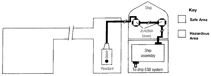
In this arrangement, discharge terminals require the ship to pass a pendant extension to the shore so that the shore operator can use the ship ESD system (Fig. 1) to stop the discharge, following a terminal ESD requirement.
Loading terminals pass an ESD pendant to the ship and encourage the ship operator to use the shore ESD system (Fig. 2) to stop the loading flow in a ship ESD situation.
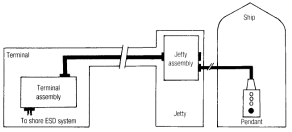
These arrangements ensure the correct shut down sequence if the relevant operator receives the ESD signal and is in a position quickly to operate the Linked ESD Systems at Both LNG and LPG Terminalspendant system. Such operators are trained to follow the correct operating/emergency procedures but much reliance is placed on rapid human intervention throughout the cargo transfer operation.
It must be emphasised that SIGTTO regards this set-up as an interim measure, and no substitute for the basic link which is represented in Figure 3.
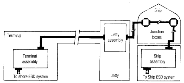
However the ESD is initiated, the link between ship and shore automatically allows selection and implementation of the correct shut down sequence. The human element, at this very stressful juncture, is removed.
In passing, it should be mentioned that LNG ESD systems are becoming progressively more extensive. Reference is now made to ESD-1 and ESD-2. ESD-1 refers to the traditional cross linked shutdown of cargo transfer, whilst ESD-2 is the terminal’s ability to disconnect the ship from the shore.
ESD-1 requires equipment to stop pumps and close valves, both in shore facilities and on the ship. Coordination of ESD-1 actions requires the interconnection of ship and shore ESD systems by means of the communication link. In other words, the basic system shown in Fig.3.
ESD-2 requires the provision of an Emergency Shut-Down and Emergency Releaseemergency release system (ERS) to disconnect the arms from the ship, each arm incorporating an emergency release coupler (ERC) to achieve disconnection with the minimum spillage of LNG (dry-break concept). Such systems may also embody a means to disconnect automatically the gangway and ship/shore links. As ESD-2 initiation is usually activated only from the shore ESD system, there is normally no need for a second ship/shore link.
Whilst such a level of sophistication is unlikely to be adopted by the LPG and Chemical gas trades, SIGTTO remains a strong advocate for the installation of the basic system (ESD-1 in LNG terms) within this sector of the gas industry.
Gas alarms
Also recommended are the use of gas alarms in terminals.
Locations for fixed monitoring detectors should be chosen carefully, with reference to possible sources of leaks (e. g. pump glands, flanges), possible ignition sources, the density of the flammable gas and prevailing winds.
In places where flammable gases should not normally be present, detectors should be set to sound an alarm at as low a level as possible, consistent with the avoidance of false alarms, since the presence of any flammable gas will show that there is a leak, pernaps some distance from the detector, which may present a serious risk. The alarm level will have to take account of the detector’s characteristics but in most cases a setting of about 10 % LFL should be enough to avoid false alarms. The greater the distance of the sensor head from the potential source of flammable gas, the lower the gas concentration that will be significant. Therefore, if there are large distances between sensors and potential leaks, it may be necessary to use a lower alarm setting and correspondingly more precise detectors.
Detectors should be constructed and tested in accordance with BS EN 50053 : 1991: Instruments for the detection of flammable gases. Detectors reading up to the lower flammable limit should satisfy the performance requirements of BS EN 50057 : 1991; BS EN 50058 : 1991 defines performance requirements for detectors reading up to 100 % gas concentration. Alternatively, detectors should be certified as complying with BASEEFA Certification Standard SFA 3007/1981; Instruments for measuring gas concentration. BS 6020 specifies standards of explosion protection by reference to BS 5501: Electrical apparatus for potentially explosive atmospheres; BS 4683: Electrical apparatus for explosive atmospheres; and Part 1 of BS 5345: Code of Practice for the selection, installation and maintenance of electrical apparatus for use in potentially explosive atmospheres.
Detectors should be certified by an established authority as conforming to an appropriate standard of explosion protection of electrical apparatus.
It is important to ensure that detectors are not only certified as explosion protected but that the explosion protection is appropriate to the atmosphere in which they will be used. For instance, flameproof equipment is’ certified as meeting the requirements of certain apparatus groups, defined in BS 4683, according to the characteristics of the gases they are likely to encounter. Equipment certified as belonging to a given apparatus group will be suitable for use in the presence of certain gases only and may not be safe for use in the presence of others.
Much useful general information concerning the use of flammable gas detectors is contained in a Guidance Note from the UK’s Health and Safety Executive. It is entitled Industrial use of flammable gas detectors and identified as Guidance Note CS1 under the Chemical Safety Services.
Example of Risk Assessment in Support of Safe Working Practice
Assessing the hazards
LPG and liquefied chemical gases have been shipped in bulk for over 60 years. This means that import/export facilities for these commodities have existed for the same period. Terminal layouts may therefore still exist which date back to the early period of liquefied gas shipments.
Terminals constructed today have sophisticated methods to assess risks associated with the handling of flammable and toxic gases which were not available when many of the older ports were built.
This does not imply older terminals are less safe than modern installations. Hazard identification has always been possible by competent plant designers and diligent operators. Modern risk analysis allows designers and operators to quantify the threat that hazards represent, making the decision to provide protective and preventative measures a more rational and logical exercise. It is certainly possible that older terminals are over-designed and have instituted procedures which cater for hazards which modern considerations would regard as unnecessary.
However, changes which can occur over time may present problems for older establishments. Shipping may increase within the vicinity, overflying may take place or other industries may move into the area. Those responsible for safe working must be aware of these changes and respond to them.
For operators at the ship/shore interface – essentially the manifold/loading arm connection – an understanding of the hazards which are currently being faced when handling liquefied gas cargoes and the likelinood of those hazards materialising into events, can lead to safer working.
The prime hazard at the ship/shore interface is spillage of cargo, either during the loading and discharging exercise or whilst the ship is in the vicinity of the shore interface. Circumstances which lead up to a release are caused by a series of uncontrolled events taking place. Once a spill has occurred the consequences create hazards which must be understood if an incident is to be brought under contro! and damage limited.
Release prevention requires knowledge of the capabilities of both ship and terminal and their limitations. These limitations will, to some extent, be site and ship specific. Operational procedures will be designed to prevent exceeding limits which lead to release of cargo. However, in the event these systems fail and a spill occurs, those responsible must know what difficulties they face.
With regard to quantifying the dimensions of hazards, a certain amount of pioneering work was conducted by the Port of Rotterdam authorities. In their study the main interest focused upon substances which are gases at ambient temperatures and liquids which have a high vapour pressure at normal temperatures and pressures. For the purposes of understanding the impact of a spill from the connection between ship and shore, the Rotterdam methods remain valid in as much as they are basically conservative.
In February 1992, SIGTTO published Guidelines for Hazard Analysis as an Aid to Management of Safe Operations. In the introduction, the objectives of the Guidelines are set out. Thev are quoted overleaf: These guidelines provide gas tanker and terminal operators with a well-tried and proven system to aid the management of safe operations in a cost-effective manner. Existing publications are primarily addressed to chemical process design and specification for new plant. These guidelines are addressed to the operators of existing gas tankers and terminals and go straight to these questions – «How may a release of flammable or toxic liquefied gas or vapour occur, how serious may the consequences be and how may the release be prevented?»
The SIGTTO Guidelines have used the methods described in the following sections to provide answers.
Concentrations of released material in Dense Gas clouds
Consider a release of LPG or a liquefied chemical gas. In order to evaluate the existing danger it is necessary to calculate the amount of the substance released in the gaseous or vapour phase.
A depressurised liquefied gas will quickly evaporate upon release, withdrawing heat from itself. The liquid can partially be entrained in the air as droplets and subsequently evaporate. The remainder of the fluid will evaporate by heat transfer from e. g. the underlying surface.
If the gas was liquefied by cooling, the liquid will form a cold pool, drawing in heat from its surroundings in order to evaporate. The boiling liquid forms a cold vapour cloud that slowly heats up prior to dispersion.
Due to diffusion and turbulence, a concentration of gas will eventually be dispersed in air. Depending on the duration and position of an observer, a source of leakage can be looked upon as instantaneous or continuous. Dispersion of both types of source can be described with a Gaussian distribution mcdel.
Much work has been carried out recently to predict the behaviour of dense gas clouds by means of mathematical models. This has been done since classical Gaussian formulae for passive gases have some limitations in describing the effects of gravity slumping, turbulence, presence of buildings and so on. The US Gas Research Institute published a report by Meroney & Lochmeyer in 1982 which identified five methods of modelling dense gas plumes. These were:
- Modified classical Gaussian plume developed for passive gases.
- Gravitational spread model establishing a plume prior to a passive gas diffusion phase.
- Volume integrated box model.
- Depth averaged slab model.
- Direct solution of three dimensional conservation equations using finite element approach.
At the time the report was written, the authors indicated that predictions of concentrations varied widely depending upon which method was adopted. Since that time, there has been a steady improvement in the correlation of the various approaches. Over a decade has elapsed during which theory has been continually modified by empirical results.
The Rotterdam study used modified Gaussian principles, the results of which were published by the Permanent International Association of Navigation Congresses (PIANC) in their Supplement to Bulletin No.49 (1985). This document is still available and entitled Dangerous Goods in Ports – Recommendations for Port Designers and Port Operators. According to PIANC the Rotterdam study considered two basic types of release – the instantaneous source in which a finite quantity is spilled and the continuous source which achieves a stable situation in vaporising a constant outflow of liquefied gas. PIANC points out that if a source has definite dimensions, a correction can be made by introducing a virtual distance. This virtual distance can be derived from the initial dimensions of the source. Calculations are performed with a point source (of adapted strength) at the virtual distance behind the actual source position.
The PIANC bulletin gives the mathematical expressions from which the Rotterdam results for cloud concentrations were derived. In the case of the instantaneous release, the expression is capable of identifying the concentration at any point within the cloud locatedby three coordinates and after an elapsed time. Continuous release formulae produce results for concentrations at any point within the cloud as do the instantaneous release equations: however, being under steady state conditions, the concentration in this instance is not time dependant.
Whilst these methods for calculating concentrations within gas clouds can be of use for those designing ports and terminals, they are not easy to use for those seeking to assess the condition of an existing plant for which they are operationally responsible.
Unfortunately, there is no simple solution to acquiring a knowledge of gas concentrations in clouds which are formed as result of accidental releases. This knowledge is, of course, fundamental in finding how far one must be from a spill in order to be safe both from a toxic point of view and a conflagration.
With the possible exception of ammonia, spills of LPG’s and liquefied chemical gases will result in heavier than air vapour clouds. As has been indicated, prediction of dense cloud behaviour is a developing science. The Rotterdam and US work has been continually refined as experience brings improvements to the empirical element and theoretical knowledge builds up. Industry, initially concerned with the handling of Hydrogen Fluoride (HF), developed a dispersion modelling tool which could evaluate the consequences of HF spills. From this project arose the HGSYSTEM which provides an openly available tool for HF and Hydrocarbon dispersion assessments. This work was sponsored by a group of some 20 companies from the chemical and petroleum industries.
Details of the HGSYSTEM are given in Appendix 3.
Appendix 3
HGSYSTEM version 3,0 information
HGSYSTEM is a package of computer models that can be used to carry out atmospheric dispersion calculations with emphasis on the dispersion of heavier than air gases over flat terrain. HGSYSTEM has been developed by Shell Research Ltd with the support and sponsorship of industry groups.
HGSYSTEM 1,0 (also known as version Nov ‘90) arose from an initial project to develop an HF dispersion modelling tool for assessing the consequence of HF spills. This work was sponsored by a group of some 20 companies from the chemical and petroleum industries in order to provide an openly available tool for carrying out HF and hydrocarbon dispersion assessments. HGSYSTEM 1,0 (and a later version 1,1 which contained no extra modelling capability) was distributed within the sponsoring companies and, for other parties, has been available on request from Shell Research Ltd/
There are no released versions of HGSYSTEM numbered 2.n.
HGSYSTEM version 3,0 adds significant capabilities to version 1,0 (1,1) and these are described below. It is again intended that the use of the programmes is not restricted to the sponsoring companies and that they are openly available for carrying out dispersion assessments. Accordingly, and until such time as improved arrangements can be made, Shell Research Limited will endeavour to supply HGSYSTEM 3,0 on request to:
- HGSYSTEM custodian.
- Shell Research Ltd.
- Shell Research Centre Thornton.
- PO Box 1.
- Chester CH1 3SH.
- UK.
HGSYSTEM requires an IBM compatible 486 (DX2/66 or faster recommended). DOS 3.3 or later, 4 MBytes of memory and 2.5 MB of free disk space. The user has to supply a text editor and graphing tools.
HGSYSTEM 3.0 contents
Shell Research Limited have developed HGSYSTEM: a package of PC-models to simulate the atmospheric dispersion of hydrocarbons and of HF.
The release scenarios which can be modelled are:
- from pressurised containment (steady state one or two-phase jets);
- from vents or stacks (steady state jet);
- from an evaporating pool (steady or time-varying dense gas plume);
- instantaneous release following vessel failure.
The HGSYSTEM modules can be used consecutively to give a source, near-field and far-field description of the dispersion process being studied. Each HGSYSTEM module can also be run as a stand-alone model. The models are suited to batch operation.
To help the new user an interactive programme is provided which guides the user through the different models and which assists in preparing the require input files.
For most modules of HGSYSTEM 3.0, two thermodynamical/chemical descriptions of the released pollutant are available to the user: full reactive chemistry and thermodynamics for an HF/water/inert gas system or a new general non-reactive multi-compound two-phase aerosol model. The latter is new to version 3 and makes HGSYSTEM applicable to a very wide range of problems.
Model description
The individual modules in HGSYSTEM version 3.0 are:
- Database programme.
- DATAPROP.
The multi-compound two-phase aerosol model needs the physical properties of each compound present in the pollutant mixture. DATAPROP generates the thermodynamical information needed by:
- AEROPLUME,
- HEGABOX,
- SPILL,
- LPOOL and HEGADAS.
The user only need specify the pollutant composition.
Source term models
SPILL
SPILL calculates the time-dependent release of a liquid, two-phase or vapour-only mixture from a
pressurised vessel. SPILL is new to version 3.
HFSPILL
HFSPILL provides time-dependent release rates for a reservoir filled with HF and is therefore the HG-specific counterpart of SPILL. Depending on the reservoir temperature and pressure, a pure vapour discharge, a pool discharge or a pressurised discharge (jet) occurs.
LPOOL
LPOOL has been contributed by EXXON. LPOOL describes the time-dependent spreading and evaporation of a liquid pool. LPOOL can handle boiling and non-boiling pools, both on land and water. LPOOL can treat two-phase, multi-compound mixtures of non-reactive species. LPOOL replaces the EVAP model.
Near-field dispersion programs
AEROPLUME/HFPLE
These models give a near-field description of steady-state pressurised releases for either a non-reactive multi:compound two-phase aerosol release (AEROPLUME) or a release of an HF/water/inert gas mixture (HFPLUME).
A unique feature of the models is that they can describe the transition from a fully airborne plume via a touchdown phase to a grounded (heavier-than-air) cloud of pollutant in one, fully integrated formulation.
Both AEROPLUME and HFPLUME also contain a reservoir/discharge model, which acts as a description of the pollutant release conditions.
AEROPLUME replaces the PLUME model.
HEGABOX
HEGABOX describes the near-field, time-dependent development of an instantaneous release of an heavier-than-air pollutant. A full thermodynamical description is available for two phase multi-compound releases, HEGABOX is new to version 3.0.
Far-field dispersion programs
HEGADAS
HEGADAS is a far-field heavy gas dispersion model, available for both steady-state (HEGADAS-S) and transient releases (HEGADAS-T). HEGADAS can be used as a stand-alone model, but will usually be run in conjunction with one of the near-field models. HEGADAS includes both HF and multi-component thermodynamic descriptions.
PGPLUME
PGPLUME is a Gaussian plume model used to give the far-field concentration distribution for an AEROPLUME or HFPLUME near-field simulation.
Utility programmes
HFFLASH
HFFLASH calculates post-flash properties (temperature, liquid fraction) of anhydrous hydrogen fluoride (HF) and generates data to be used by HEGADAS or HFPLUME.
POSTHS/POSTHT
These programmes facilitate parsing of the HEGADAS output files so that the user can plot results.
PROFILE
PROFILE is a post-processor that superposes a Gaussian profile upon the AEROPLUME top-hat concentration profile and so allows plume concentration iso-contours to be estimated.
GET2COL
GET2COL is a utility to retrieve any two columns from a data file whilst ignoring embedded text.
HGSYSTEM 3.0 DOCUMENTATION
A user manual and a technical reference manual are supplied with HGSYSTEM 3.0: The — technical reference manual emphasises new work specific to version 3.0. Copies of the technical reference manual to HGSYSTEM 1.0 will be available on request but will not be routinely distributed as part of the HGSYSTEM version 3 package.
These include the conditions under which the latest versions may be obtained. It must be said the system cannot at this stage be regarded as «user friendly» since it requires specialised knowledge to both input and to interpret results. The original sponsors are, in the main, major companies who use HGSYSTEM as an «in-house» tool. However, since HGSYSTEM can be obtained for only very modest administrative charges, a number of consultancies have acquired the system and are offering an assessment service for specific facilities. These organisations are known to the HGSYSTEM custodian identified in Appendix 3.
Because of its potential to become a neutral or buoyant gas, it is possible to estimate the effects of ammonia, at a point remote from the spill location, by using simplified methods. Details of this technique are given in Appendix 4.
Appendix 4
The far field effects of neutral or buoyant gases
In Essential Features for Safe Operations: Emergency Shut Down (ESD), Risk Assessment, and Hazard Analysis“Desirable Features”, the concentrations of released material in dense gas clouds are assessed. Whilst LPG’s and Liquefied Chemical gases will, save under exceptional circumstances, form heavier than air vapour clouds, Ammonia has the capability to form lighter than air clouds upon release in the liquid form.
It is possible to determine concentrations, remote from the spill point, when the gases resulting from a continuous release, are neutral or buoyant in air. Under these special conditions relevant mathematical expressions can be greatly simplified.
Standard Gaussian plume methods are appropriate and very easy to apply from tables or graphs. These give the variation of lateral and vertical dispersion parameters, σy, and σz, with both horizontal distance and stability class. The centre-line concentration can then be calculated from the formula:
where:
- Q = source release rate (kgs1);
- u = wind speed (ms-1);
- σy σz = cloud spread (m);
- C0 = concentration (kg m3).
Off-centre-line concentrations are obtained by assuming a normal distribution with standard deviations σy and σz, in the lateral and vertical directions respectively.
These expressions appeared in Volume 5 number 4, 1992 of the «Journal of Loss Prevention in the Process Industries» and were quoted from a much earlier work by R.H. Clarke entitled «A model for short and medium range dispersion of radionuclides released to the atmosphere». This is identified as an NRPB publication R91 dated September 1979. Details of standard deviations are to be found in that paper.
Gas concentrations are obviously affected by weather. Unless calculations are being made against a specific set of conditions it is normal, in the process of determining where hazards lie, to use weather categories classified by Pasquill. This regime is shown in the table below.
| Table 1. Stability categories in terms of wind speed, insolation and state of sky | |||||
|---|---|---|---|---|---|
| Surface Wind Speed (m/sec) | Insolation | Night | |||
| Strong | Moderate | Slight | Thinly Overcast or ≥4/8 low cloud | ≥ 3/8 cloud | |
| <2 | A | A-B | B | – | – |
| 2-3 | A-B | B | C | E | F |
| 3-5 | B | B-C | C | D | E |
| 5-6 | C | C-D | D | D | D |
| >6 | C | D | D | D | D |
| (for A-B take average of values for A and B etc.) | |||||
Strong insolation corresponds to sunny midday in midsummer in England, slight insolation to similar conditions in midwinter. Night refers to the period from 1 hr before sunset to 1 hr after dawn. The neutral category D should also be used, regardless of wind speed, for overcast conditions during day or night, and for any sky conditions during the hour preceding or following the night as defined above.
The foregoing illustrates that methods are available to determine the distribution of gas concentrations resulting from a spill at the ship/shore interface. The complex nature of assessing dense cloud dispersion and the continuous evolution of those methods have also been emphasised. The latest computer programmes dealing with dispersion have been identified. A definitive publication has very recently become available which covers the thermodynamics of cloud behaviour. This work is entitled «Loss Prevention in the Process Industries» and is edited by Frank Lees. It comes in three volumes and handles the subject matter in an advanced analytical fashion. Volume deals, inter alia, with cloud dispersion. The ISBN is 0750615478.
Spill and Cloud Effects
To evaluate the consequences of a release of liquefied gas, the effects of that release must first be defined.
(I) Toxicity
Toxic substances which when released, evaporate and are dispersed in the atmosphere can create health hazards over a distance, downwind of an incident. The most important mechanism for poisoning by toxic substances over large distances is inhalation. The degree of poisoning can vary from irritation via curable and incurable harm up to lethal damage. The gravity of the poisoning effect depends on exposure times, concentration of the toxic substance and the sensitivity of the victim.
As a hazard criterion for lethal effects, readings in excess of the LC lowest value (lowest lethal concentration) at a given distance, can be used.
The LC lowest Lethal concentration Lowest: the lowest concentration of a substance which has caused death to men or animals.x appears to be the most suitable system for identifying distances over which acute danger exists. The MAC MAC: Maximum Acceptable Concentration (over a long period of repeated exposure).x is ruled out since this value takes into account long term effects.
(II) Explosion
If ignition of a flammable substance occurs with some delay after release, the material can be diluted in air so as to form an explosive mixture. In this case the vapour cloud will usually deflagrate, causing a pressure shock wave. This overpressure Causes mainly indirect effects upon personnel, because people are buried under collapsing buildings or are hit by shattered glass. Some limit values for overpressure are given below:
| Table 2. Limit values for overpressure | |
|---|---|
| Incidental breaking of glass | 0,01 bar |
| Dangerously shattered glass (e. g. window panes) | 0,03 bar |
| Reparable damage to structures and buildings | 0,10 bar |
| Heavy damage to structures and buildings | 0,30 bar |
| Eardrum rupture, threshold of severe damage to facility, tanks and other equipment | 0,5 bar |
To estimate the effects of a vapour cloud explosion, first the amount of material between the explosion limits has to be calculated. Once this is known, the effect of deflagration can be derived by comparison with TNT-curves and using the energy available in the calculated amount. As a criterion for danger, the distance at which a maximum overpressure of 0,03 bar occurs is used.
Some limit values for heat radiation dose during short exposures are:
| Table 3. Limit values for heat radiation dose | |
|---|---|
| Threshold of pain | 65 kJ/m2 |
| First degree burns | 125 kJ/m2 |
| Second degree burns | 250 kJ/m2 |
| Third degree burns | 375 kJ/m2 |
If a person is exposed to radiation equivalent to 10 KW/m2 for a period of 40 seconds, a radiation dose of 400 kJ/m2, the results will be fatal.
Radiation levels of 16 KW/m2 will spontaneously ignite wood, while fires giving radiation at 32 KW/m2 will severely damage uncooled steelwork. Sources: PIANC & Arthur D. Little.
(III) Flammable Limits
In principle, a cloud will be flammable until it is diluted below the Chemical Composition and Physical Properties of Liquefied GasesLower Flammable Limit (LFL) applicable to the material within the cloud. However, concentrations near cloud boundaries tend to fluctuate. The half – LFL convention has been adopted in the USA and UK such that the flammable range occurs at a distance which is given at 50 % LFL by cloud dispersion calculations. Sources: PIANC & Arthur D. Litt.
The Outcome of Hazard Analysis
Text above confirms that it is possible to calculate gas cloud concentrations which result from a release of liquefied gas. «Spill and Cloud Effects» gives the effects of toxicity, deflagration and thermal radiation on people and property. An analysis can thus be made, which can first locate concentrations of hazardous material, then assess how far away from a release personnel and structures must be to avoid injury or damage.
The effects of incidents are therefore a function of the distance, in metres, over which certain hazards exist. Within, and to some extent without the boundaries of an installation, contours can be plotted which show areas always assessed as safe and those which, from time to time, might become dangerous. For materials which are both flammable and toxic, both sets of «effect» distances should be worked out using worst case weather conditions.
Effect distances from the Rotterdam Study
Effect distances: this is the distance from a spill, release or fire at which the event is of no consequence to life or property.
The Rotterdam Study was comprehensive in terms of the different cargoes which it covered. It devoted some time to LPG and chemical gases-with interesting results – particularly regarding differing spill rates.
For a hazard evaluation, it is necessary to choose a credible incident scenario. This choice is important for the outcome of any analysis.
In the study, four possibilities for release of material were chosen:
| Table 4 Material Release Options | |
|---|---|
| Partial failure of containment-aperture area of | 1 cm2 |
| Partial failure of containment-aperture area of | 5 cm2 |
| Partial failure of containment-aperture area of | 10 cm2 |
and total failure of containment.
An area of 10 cm? is roughly the largest hole that forms a restriction to outflow. For larger areas, the outflow can be looked upon as instantaneous and is hence comparable with total failure. The smaller areas were chosen to consider the effects of a restricted outflow, that is over a longer period.
In case of restricted outflow, as with partial failure, it was assumed that liquid gases emerge as liquid and flash into vapour immediately and completely. In case of total failure the assumption was made that initially just a fraction evaporates (adiabatic flash) and a pool forms.
Read also: Accident Prevention The Use of Hoses & Hard-Arms at Marine Terminals Handling Liquefied Gas
The Rotterdam Study used credible spill quantities which could be expected to occur between ship and shore. Although basically dealing with ruptured containers, the Rotterdam results could equally apply to loading arm incidents.
| Table 5. Toxic Gases | ||||||
|---|---|---|---|---|---|---|
| Product | Type of Containment | Mass of Contents (kg) | Distances (m) to Lethal Concentration (LC) lowest | |||
| < 100 | 100-300 | 300-500 | > 500 | |||
| Ammonia | Cylinder | 860 | – | 0 | + | – |
| Vinyl-chloride | Tank container | 16 000 | – | – | 0 | +(1 400) |
| Methyl-bromide | Tank container | 14 500 | – | 0 | – | +(800) |
| Hydrogen-chloride | Cylinder | 82 | – | 0 + (*) | – | – |
| Chlorine | Cylinder | 360 | – | – | 0 | + (800) (*) |
| 0: due to a leak through a cross sectional area of 10 cm2; +: due to catastrophic failure; (*); containment is emptied so fast when damaged that a leak through a cross sectional area of 10 cm2 causes an instantaneous spill. | ||||||
Using the calculation methods described above and the limits set down in above, the results can be summarised as shown in Tables 5 & 6.
| Table 6. Flammable Gases | ||||||
|---|---|---|---|---|---|---|
| Product | Type of Containment | Mass of Contents (kg) | Distances (m) to LC lowest | |||
| < 100 | 100-300 | 300-500 | > 500 | |||
| Propane | Tank container | 8 000 | – | 0 | – | + (565) |
| Vinyl-chloride | Tank container | 16 000 | – | 0 | + | – |
| 0: due to a leak through a cross sectional area of 10 cm2; +: due to catastrophic failure. | ||||||
In performing the analysis, a very stable atmosphere (Pasquill class F, see Table 1) and a wind speed of 2 m/sec was assumed. Further investigations showed that – for the Rotterdam area – Pasquill stability Class D (neutral) and wind speed 5 m/sec are more representative. This emphasises that ports should take into account locally prevailing atmospheric conditions when performing effect distance calculations.
The PIANC Bulletin No.49 used the Rotterdam method to analyse an event at the ship shore interface in the following way.
They acknowledge, with bulk cargoes, a typical incident is spillage due to rupture of the ship-shore connection. It is assumed that 90 seconds elapse before the spill is noticed and the emergency shut down system is activated; also that 30 seconds are required to fully close the ship and/shore valves. The amount of dangerous substances spilled can then be conservatively estimated from the following expression:
in which:
- QS = quantity spilled.
- PS = pump flowrate in m3 per hour.
The incident can be considered as an instantaneous release and its effects calculated using methods based on the Rotterdam study. Sample calculations have been made for two flammable gases; ethylene and propylene. The results are shown in Table 7.
| Table 7. Maximum allowable pump flowrate consistent with an effect distance of x metre | |||
|---|---|---|---|
| Product | Effect distance based on a two-minute spill | ||
| 100 m | 300 m | 500 m | |
| Ethylene | 50 m3/h | 250 m3/h | 1 000 m3/h |
| Propylene | 50 m3/h | 250 m3/h | 1 000 m3/h |
PIANC stressed that these figures only serve to illustrate the principles. The underlying calculations are based on a hypothetical accident scenario which may not be applicable in all ports or in a given situation.
The scenario used in this case contains the following assumptions:
- Climatic conditions: stability class F (very stable) and wind speed 2 m/s.
- Duration of spill 120 s based on closing time of valves = 30 s and reaction time of 90s.
- Ignition of flammable cloud when the amount of flammable gas-air mixture is maximum.
- lethal overpressure value set at 0,03 bar corresponding with dangerously shattering of window panes.
SIGTTO’s guidelines for hazard analysis as an aid to management of safe operations
The foregoing sections have chronicled the developments that have introduced risk assessment to the Ship/Shore interface as it relates to Liquefied Gas movements.
The Rotterdam Study set out methods which enable Designers and Operators to discover where dangers lie throughout the period when a credible incident is evolving to its eventual termination.
Although this work has been superseded by more accurate systems, the results are conservative and model a number of products which are not readily available.
SIGTTO’s Guidelines take a further step in providing information upon which management may act. As in the case of the Rotterdam studies, they identify the hazard and quantify its effects. In addition the Guidelines provide a means whereby the likelinood of a hazard developing into an incident can also be quantified. Management can, therefore, now identify the realistic risk scenario and concentrate upon its removal or reduction.
The Guidelines can, of course, be applied to all aspects of Gas Tanker and Terminal activity but they are of particular value if directed to the loading arm/ship’s manifold – an area many consider runs the highest risks.
Management role
It is recommended that terminal managers apply the method of hazard analysis proposed in SIGTTO‘s Guidelines to the ship/shore operation. Unlike earlier literature, prompted by the Rotterdam Study, the Guidelines show clearly how to recognise hazards and how to judge their impact as an incident via the concept of effect distances. Deriving effect distances has been made «user friendly» by the development of a series of characteristics from which this information can be obtained. The gases, for which details are available, are LNG, LPG and Ammonia. Chemical gases are not included. This Information Paper No.16 provides further details of the earlier Rotterdam Study results relating to certain chemical gases.
Effect distances offer comfort provided they are less than actual distances. Frequently this will not be the case. Under these circumstances management will need to assess just what is their exposure. Much can be done by comparatively simple means to alleviate risk. If windows are thought to present risk from flying glass, then toughened glass, plastic film, or repositioning may prove effective. Initial reactions concerning effect distances envisaged personnel remaining passively within the range of whatever radiation or toxic gases a potential incident might generate. Views on the actions of an informed workforce are now being taken into account when planning safety measures. People are no longer regarded as remaining stoically in a dangerous position; they are expected to be proactive and attempt to save themselves. This being the case, apparently modest protective measures can meet with success. This is particularly true of radiation hazards where even light shielding greatly reduces harmful effects.
Procedures can also play an important role in risk reduction. The clear instructions for purging loading arms given in Safe Working Practice at the Ship/Shore Interface with Particular Reference to Purging of Loading Arms“Instrument checks during loading and discharging”, iltustrate this point. LPG/chemical gas operations at the ship to shore interface follow procedures which are sufficiently robust to obviate the need to have instrument checks. Procedures for standard operations should be backed up by clear and concise instruction on what should be done to contain and limit the effects of a hazard materialising as an incident. Early action and alerting of emergency services will result in limiting injuries and damage.
This new sense of realism regarding the combatting of risk has been brought about by managements being able to actually come to grips with what can occur. They have become aware that they can take action to protect against some awesome event which hitherto could only generate a mood of fatalism.