Building on the general principles set out in the article «Philosophy and general requirements in the gas industryGas industry requirements», the purpose of this article is to provide information on actual systems Emergency Shutdown System in service. As the worked example in this article is intended to be as generic as possible, it contains references to a variety of elements that may be encountered in gas carriers. Because of this, some of the diagrams may show combinations of cargo machinery that would be unlikely in a single ship. For example, the first logic diagram shows both a gas fuel compressor (found in LNG carriers with dual-fuel steam or diesel-electric propulsion) and reliquefaction plant (found in LPG carriers and most LNG carriers without dual-fuel propulsion).
While this article also discusses shore facilities, this is only in the context of their interaction with the ship. The information on terminal equipment and systems is, therefore, more general. The design of shore systems is outside the scope of the IGC Code and of this article.
Although, in LPG ships, it is not usual to distinguish between ESD functions concerned with loading or unloading from those associated with other operations, LNG carrier designs commonly do so and this diagram is intended to show how the functions relate to one another.
a Based on the IGC Code core requirements centred on closure of ESD valves, the ESD-1 system handles cargo loading or unloading transfer operations and incorporates an ESD link to coordinate ship and shore actions.
b Other IGC Code requirements that are centred on protection of individual tanks from damage caused by overfilling, high pressure, vacuum, etc, are handled by the Tank protection system.
c Gas burning safety system – shuts down the gas fuel supply to the engine room of LNG carriers under certain emergency conditions.
Note that there is a degree of overlap between the functions so, for example, although the gas burning safety system is primarily seen as an «engine room system», it will also shutdown to protect Gas Freeing of Cargo Tanks on Liquefied Natural Gas Carriers cargo tanks against low vacuum.
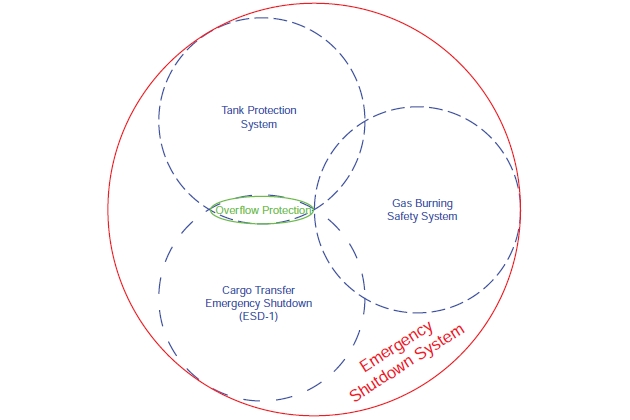
Although Overflow protection has an important role during loading, the risk is present whenever liquid is being transferred on board so it resides in both the ESD-1 and tank protection areas of the diagram.
Cargo Transfer Emergency Shutdown System (ESD-1)
As an example, the following Simplified Diagram of Loading Flow shows cargo flow at an export terminal as described in this article. Liquefied gas is pumped from shore tanks to the shore ESD valves at the edge of the loading platform – this distance can be considerable. The flow then divides, typically passing to the ship’s manifold via two or three liquid loading arms, and then to the ship’s tanks. This arrangement is similar for all gas carriers.
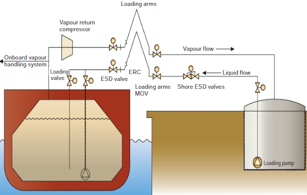
However, on the vapour side, the displaced vapour and boil-off may be managed in different ways depending on the product, the type of vessel and the trade. Common examples of this may include one or more of the following options:
- vapour return to shore, perhaps with the aid of a vapour return compressor as illustrated;
- increasing tank pressure, as in the case of pressurized tanks for example;
- onboard reliquefaction;
- combustion onboard.
General
Which system minimizes risks when pumping liquefied gases?
This is an ESD system that minimizes the potential risks during the transfer of liquefied gases between ship and shore loading and unloading installations. It provides a quick and safe means of stopping the transfer of cargo and isolating ship and shore cargo systems in a controlled manner, either manually or automatically, in the event of fault conditions that affect the ability of the operator to control safely the transfer of cargo.
Most export terminals, and an increasing number of import terminals, now have a second level of protection providing for the rapid disconnection of the loading arms from the ship.
These two levels of cover are known as «ESD-1» and «ESD-2».
As the receiving tanks are often several kilometres from the transfer pumps, the kinetic energy in the moving liquid can be considerable and the potential hazards of surge pressure must be considered. For this reason, coordination of ESD-1 actions requires the interconnection of ship and shore ESD systems by means of a suitable communication link.
The following diagram shows the basic components of a ship’s ESD-1 logic. The numbers 1-6 relate to the initiation signals described below.
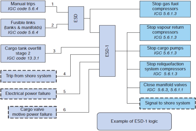
«Dashed» boxes represent functions that are not specifically defined by the 1993 IGC Code. Clause numbers in all logic diagrams in this article relate to the 1993 version of the Code and will be different in later editions.
The extra route, labelled «ESD» in this example, is to allow LNG carriers to maintain a path for the safe disposal of vapour by avoiding unnecessary disruption to gas burning or the GCU. It may also be appropriate, in the case of Contingency Plans for Liquefied Natural Gas CarrierLNG carrier reliquefaction plant, to treat this facility in a similar manner to the gas fuel system or GCU system. The gate is unnecessary in LPG carriers, signals 1 and 2 being input directly to the ESD-1 logic gate.
ESD Actions
ESD-1 (loading). Initiation of ESD-1 should cause visual and audible alarms together with the following actions:
| Ship Action | Shore Action | ||
| Transmit ESD trip signal via ship/shore link | → or ← | Receive ESD trip signal from ship | |
| Receive ESD trip signal from shore | Transmit ESD trip signal via ship/shore link | ||
| Trip ship’s vapour return compressors | Trip loading pumps and open spill-back valves | ||
| Close manifold valves in 25 ~ 30 seconds | Close shore ESD valves in 10 ~ 15 seconds | ||
The shore actions above are typical for export terminals and may vary to suit the design of the plant. In some ships different machinery may be involved in this trip, such as reliquefaction plant.
ESD-1 (unloading). Initiation of ESD-1 should cause visual and audible alarms together with the following actions:
| Ship Action | Shore Action | ||
| Transmit ESD trip signal via ship/shore link | → or ← | Receive ESD trip signal from ship | |
| Receive ESD trip signal from shore | Transmit ESD trip signal via ship/shore link | ||
| Trip ship’s cargo pumps | |||
| Close manifold valves in 25 ~ 30 seconds | Close shore ESD valves in 30 ~ 60 seconds | ||
The information relating to closure of shore ESD valves given here is for general information only and the actual arrangement will reflect the specific requirements of each terminal. Import terminals sometimes incorporate additional actions into their ESD-1 logic, eg trip return gas blower.
ESD-2 (loading or unloading). Initiation of ESD-2 should cause visual and audible alarms together with the following actions:
| Ship Action | Shore Action |
| None | Immediately initiates ESD-1 The purpose of this signal is to guarantee transfer pumps are tripped before arm release. Some terminals have alternative arrangements to ensure safe release.x |
| Closes loading arm ERS valves within 5 seconds | |
| Uncouples loading arm within 2 seconds of ERS valve closure |
No action is necessary on the ship but it is recommended that ESD-2 is signalled by a loud audible warning on the jetty to warn personnel to stand clear of the ship’s manifold area and the jetty working platform.
ESD-2 requires the provision of an emergency release system («ERS») to disconnect the arms from the ship, each arm incorporating a powered emergency release coupler («ERC») to achieve disconnection with minimum spillage (dry-break concept). Many terminals will incorporate a surge relief system. In the case of loading terminals, this may comprise a fast opening fail-safe dump valve that diverts liquid flow to a surge drum while the ERS and ESD-1 valves are closing, minimising surge.
At a few terminals systems may also be in place to disconnect the gangway automatically.
Although the ESD-2 logic is arranged as described above in the majority of LNG terminals, loading arms at some terminals are designed with an alternative logic, where an ESD-1 event triggers closure of the isolating valves within the ERC, potentially saving time if the situation then progresses to ESD-2 level. The disadvantage of this arrangement is that liquid is trapped within the ERC and in the ship’s manifold for what might be a protracted period. Although many LNG carriers are now provided with liquid relief valves in the section of manifold outboard of the ESD valve, it is only in recent years that the need for such valves has been recognised and so a significant number of gas carriers will not be fitted with them.
Comments on ESD-1 actions. The loading arm swivels are particularly susceptible to damage caused by overpressure and it is therefore important that closure times of ship and shore ESD valves are selected with due regard to flow direction so that surge pressure is controlled upstream of the loading arm. Shore ESD valves should therefore close before the ship’s manifold valves at export terminals, but after the ship’s valves at import terminals.
The IGC Code states that the ship’s manifold valves should be closed within 30 seconds of initiation. As it would be impractical to re-adjust closure times each voyage to suit the particular terminal, the ship’s manifold ESD valves are normally standardised so that they close in 25 ~ 30 seconds.
Cargo valve remote control systems on many gas carriers use hydraulic actuators and for ESD valves these should be provided with pressure and temperature compensation to ensure consistent closing time.
As many types of valve actuators require hydraulic or pneumatic pressure to both close and open, the IGC Code requires the designated ESD valves to fail-closed on loss of motive power. ESD valves with hydraulic actuators are often provided with local accumulators for this purpose; while in pneumatic systems, compliance is sometimes achieved by providing actuators with individual air reservoirs. Other alternatives include spring-to-close devices. The actual arrangement will depend on the specific type of actuator but, without such provision, the valves could stay open even though they received a «close» signal from the ESD system. The valves must be capable of local manual operation to ensure they can be closed in the event of malfunction of the actuator itself and should be provided with clear indication of valve position.
The loading of liquid nitrogen on gas carriers is now rare but, if the manifold is provided with an LN2 connection, then it is recommended that this also be closed under ESD-1 action, facilitating automatic disconnection under ESD-2 action at terminals so equipped.
Note that it may be only the vapour return gas compressors that are tripped as part of ESD-1 action.
Manual trips for gas fuel compressors in LNG carriers built to earlier versions of the IGC Code were usually separate from that required for the ESD system, as discussed in point «Gas Burning Safety System» below. This was chiefly to ensure that ESD-1 events, such as a trip from shore or cargo tank high level, did not also disrupt the safe disposal of excess pressure through the gas burning system. Although this meant that the gas fuel compressors were not tripped by the deck manual trips, they could still be tripped from the cargo control room or locally. However, the introduction of operations designed to supplement natural boil-off by forced vaporization of cargo means that LNG is now often present in deck pipelines at sea. It is therefore recommended that the ESD system manual trips and fusible links also trip gas fuel compressors as illustrated in the ESD-1 Logic Diagram in point below. A suitable test function should be provided to facilitate ESD-1 system testing without disrupting gas burning.
Where reliquefaction systems are installed the action on an ESD-1 trip will generally be to shut down the plant, together with any associated condensate return pumps. However, special consideration should be given in the case of an LNG carrier where boil-off gas compressors are also required to service the GCU.
In general, inert gas generators in LNG carriers are never connected to the Cargo System – Tank Construction cargo system when an LNG carrier is in the cold condition and connection to ESD-1 trip logic serves no useful purpose. Overpressure cargo tank protection by tripping the inert gas generator is therefore a function of the Tank Protection System described in the point «Tank Protection» below. This may be different to some LPG carriers where, if cargo pumps fail, the inert gas system can be used for the emergency discharge of cargo by pressurizing the tank. In this case it should be tripped by ESD-1.
ESD Initiation
Initiation Signals
An ESD-1 trip may be initiated by the following:
| Ship Initiation | Shore Initiation | ||
| 1 | Operation of manual trip | A | Operation of manual trip |
| 2 | Fire at tank domes or manifold area | B | Fire in terminal area |
| 3 | Overfilling of any cargo tank (HHL) | C | Overfilling of receiving tank (import terminal) |
| 4 | Shutdown signal from shore via link | D | Shutdown signal from ship via link |
| 5 | Loss of electrical power | E | Loss of electrical power |
| 6 | ESD logic failure | F | ESD logic failure |
| 7 | Loss of system pressure in the cargo valve remote control system | G | Loss of actuating power to the common loading arm manoeuvring system or to the ERS of individual loading arms |
| H | High level of liquid in surge drum (where provided) | ||
| I | Excessive movement of ship from berth (stage 1 – pre-alarm) | ||
| J | Activation of ESD-2 | ||
Some of these initiators will not apply at all terminals.
An ESD-2 trip should be initiated in the event of the following conditions:
| Ship Initiation | Shore Initiation | |
| Not activated from ship | K | Operation of manual trip |
| L | Excessive movement of ship from berth (stage 2 – disconnect) | |
Comments on ESD-1 Initiation Signals
Ship.
Signal 1Operation of manual trip. Will be derived from manual switches or push buttons. The IGC Code requires a minimum of two points, one of which must be in the cargo control room (or equivalent). Manual trips should be located so they can be reached reasonably quickly by anyone spotting a serious hazard. Consideration should be given to installing additional points where free access is restricted, by fore and aft pipelines for example. The optimum position is alongside primary escape routes. The manual ESD should not form part of any other shutdown system.
Signal 2 Fire in the cargo area. Will be derived from fusible links installed in the cargo area. The IGC Code requires sensors at the tank domes and the loading stations that will operate in the range 98 ~ 104 °C. Originally these comprised a pipefitting blocked with a soft metal plug that would melt on contact with fire, releasing air pressure from the air security pipework. They are often still called fusible plugs for this reason. This type of system is illustrated in the point «Linked ESD Systems at Both LNG and LPG TerminalsPneumatic ESD Link System».
The first electrical systems employed bi-metallic switches but these tended to be delicate and unreliable. Fault detection could be difficult and later systems often incorporated additional wiring to aid fault finding.
Thermal fuses are commonly used for this application. These devices are readily available in the appropriate temperature range and have the advantages of being both cheap and reliable. The usual arrangement is to bury the thermal fuse in a silicon mould using a gland nut as a former, as illustrated in the figure.
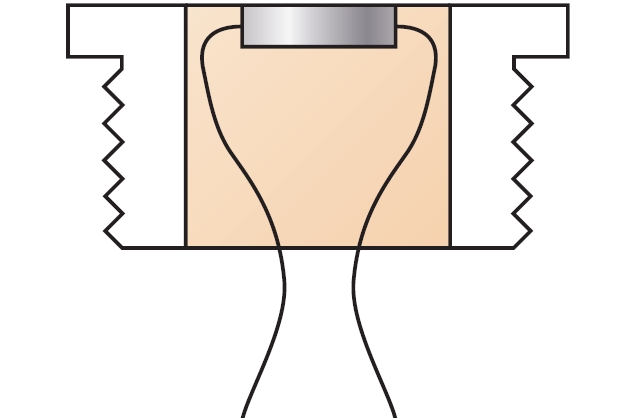
Two such modules, connected in parallel, can be installed in a 4-way junction box to create a standard fusible link unit. Fusible link units can then be series-connected and monitored by an IS relay mounted in the safe area.
The IGC Code requires that where separate gas and liquid domes are fitted, both should be protected.
Signal 3Overfilling of any cargo tank. In the system described here is derived from the higher of two «spot» level sensors in each of the ship’s cargo tanks. In this example this HHL sensor will be independent of the main level measuring system and arranged so that the operation of any one sensor will initiate ESD-1. This is covered in greater detail under «Cargo tank overflow protection» on below, where subjects such as two-stage overflow protection and signal blocking are also discussed.
Signal 4Shutdown signal from shore. Will be transmitted by means of a ship/shore link. These are discussed in the article «Linked ESD Systems at Both LNG and LPG TerminalsESD Terminal».
Signal 5Electric power failure. In the event of electrical supply failure, the ship’s cargo pumps and electric-driven gas compressors will shut down without any intervention from the ESD system. Depending on the actual arrangement, the ship’s manifold ESD valves could remain open until hydraulic pressure collapses. However, without signal 5 shore loading pumps and compressors would continue to run under ship’s blackout conditions.
Signal 6Loss of actuating power to the cargo valve control system. The source of this signal will depend on the type of valve actuators employed. For hydraulic or pneumatic systems the source should be a low-low pressure switch installed in the common supply line downstream of any isolating valve. Pre-alarms will also be fitted and signals should have suitable time delays.
Note: the primary purpose of this signal is to stop transfer in the event the operator loses the ability to adjust valves in the system, particularly tank loading valves or pump discharge valves. Therefore, the pressure being monitored must not be a maintained supply such as a manifold ESD valve accumulator.
Signal 7ESD logic failure. Historically, this signal was added when ESD systems started to rely on early electronic logic devices, such as programmable logic controllers, and was intended to cover an internal system failure (such as fuse blowing in the system). The necessity for such an input will depend on the type of logic and the level of redundancy but, with a robust DCS/IAS, a separate signal may be unnecessary.
It is recommended that the ESD system be designed to indicate positively the source of a trip.
Shore. For completeness, this short paragraph will cover some of the shore elements shown in the table at the beginning of this article. Many factors will determine the exact arrangement of shore ESD systems, not the least of which is whether it is an export or an Dynamic Simulation and Optimization of LNG Plants and Import Terminals import terminal. A detailed discussion of the inputs to shore ESD systems is outside the scope of this article, which is intended only to cover the parts affecting the gas carrier, ie the cargo loading or receiving system.
Signal IExcessive movement of ship away from berth. Is usually derived from a first stage signal of the loading arm apex angle and/or slew angle transmitter.
Signal JActivation of ESD-2. Is derived from interlocked monitoring circuits in the ERS and forces ESD-1 activation to ensure that in the event of premature release, cargo flow will have ceased.
The other signals listed are similar to their counterparts on the ship.
Additional ESD-1 Trips. The simpler the system, the easier it will be to understand, test and maintain and the ESD-1 initiators described above will normally be adequate. Advances in technology have opened up the opportunity to engineer a whole range of automatic initiators of linked ESD systems but great caution should be used when considering further initiators beyond those required by the IGC Code and mentioned above on ships and those currently established on shore. Any such proposals should be subject to rigorous assessment to ensure that there is a real benefit.
Cargo Tank Overflow Protection
Although IGC 13.3.2 deals with overflow control it is clear from the wording that the counter measures are aimed at preventing an overflow during loading. However, the majority of overflows have actually occurred during discharge due, for example, to a valve being left open to a full tank.
As stated earlier, in addition to an independent high level alarm, the IGC Code requires another level sensing device to close a valve to prevent tank overflow. The Code allows this to be either the «emergency shutdown valve» or «another valve». Although not stated, this infers that the valve should be on the tank filling connection. As the manifold valves are the designated ESD valves in LNG and many LPG carriers, the level of protection from solely closing the manifold valves would clearly be seen as inadequate. Perhaps the simplest way to enhance the basic requirements of the IGC is to also arrange for the tripping of cargo pumps as part of overflow protection. In many ships this provides an adequate level of protection. However, many vessels are generally equipped with level measuring and protection systems that allow a more sophisticated solution to be adopted. The «high level alarm» requirement is now typically met by duplicated sensors giving two independent alarm signals, while CTS systems generally provide up to four more «alarm» outputs.
Although the arrangement shown in the picture would not be practical in all types of gas carrier, it is often applied to LNG carriers and satisfies the IGC requirement for independent signals. This design has been used for many years and provides a proper level of protection with appropriate redundancy. For clarity, only three tanks are shown.
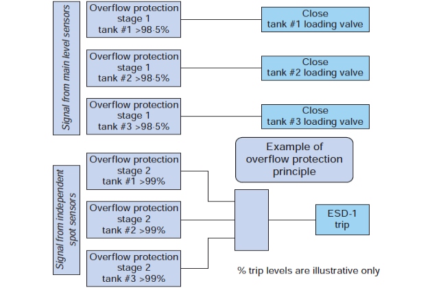
As the diagram shows, there are two stages of shutdown: firstly closing the tank loading valve in the affected tank and then, should the level continue to rise, initiating an ESD-1 trip to halt the entire transfer process. In addition, audible and visible alarms are given at appropriate points.
Main sensor refers to the primary CTS Read «main level gauge» in trades where no CTS is provided.x level gauge. Most systems provide up to four volt-free contacts for alarm purposes.
Spot sensors, which trigger at a specific level, operate independently of the CTS. There is one output per sensor and modern systems have two sensors per tank.
The following sequence will occur as the tank level rises:
- Pre-alarm – sourced from the lower of two independent «spot» sensors. It is recommended that this be set so that, when loading at maximum rate, it operates about 15 minutes before reaching normal filling level. In this example, this will be around 97 % volume.
- Close tank loading valve – sourced from main sensor and set at about normal filling level. Typically this will be 98,5 % for a membrane system or 99,5 % for a spherical tank, the actual figure being calculated to take into account trim and list and to avoid premature actuation.
- ESD-1 – sourced from upper spot sensor (HHL) to prevent the tank becoming liquid full. Typically settings are 99,0 % for membrane or 99,7 % for a spherical tank. Note that this will leave the tank overfilled and action will have to be taken to reduce the level to normal before sailing.
If allowed to continue, the above sequence would close each tank loading valve in turn before the level reached the HHL shutdown sensor. When the last valve closed, the effect would be to close against loading flow without ESD-1 initiation. To ensure that this is not possible, the control logic must be designed to initiate an ESD-1 trip if all loading valves are closed or, in the case of the last valve, are closing. However, even with this degree of sophistication, good operating practice would ensure that this critical stage of loading was only carried out under close direct supervision.
An advantage of using main CTS sensor for closing the loading valve is that the trigger point can be finely adjusted to suit the actual valve closing characteristics. By contrast, most spot sensors have very limited adjustment capability.
Reliability, rather than extreme accuracy, is more important to the ESD-1 signal, which the independent sensor provides.
Read also: Safety, Risks and Security Aspects in Liquefied Natural Gas Industry
As the main gauge is monitored throughout loading, the operator will have been alerted to any problems with this system that might exist and this gives reasonable confidence that the signal to close the filling valve will actually work. Similarly, sourcing the pre-alarm from the independent system increases the likelihood that any faults in that system will be revealed before ESD-1 level is reached, at the same time providing a cross-check of the accuracy of the two systems.
All level signals should have suitable time delays to avoid premature shutdowns caused by surface motions of the cargo.
Signal blocking. To avoid unnecessary alarms caused by the cargo motions, it is normal practice to disable («block») the level sensors at sea. The obvious danger with this is that someone will forget to unblock the signals before a transfer operation begins. Although the risk is mitigated to some extent by having prominent warning indicators, it is recommended to also have effective interlocking. For example, it should not be possible to simultaneously block both filling valve close signals and the ESD-1 trip level signals in the same tank, and it should not be possible to open the manifold valves when any ESD-1 trip level signal is blocked.
Blocking of individual sensors is also necessary in two other circumstances:
- if a tank becomes overfilled to the point that the upper independent sensor operates, this sensor will have to be blocked to enable cargo pump starting so as to reduce the level;
- the most positive way of testing the whole system is to deliberately overfill each tank by a controlled sequence of internal transfers for which selective blocking is necessary. To satisfy periodic survey requirements such a test is normally carried out at the end of loading the first cargo on delivery or after refit.
In service it is also common practice to temporarily block the filling valve close signal in the last tank to be filled while «topping off» and during line draining.
Custody Transfer and Independent Level Alarm systems may be provided with physical «block switches» and sometimes software blocking as well, and this may not be immediately obvious to the operator.
Testing. In the system described above, the lower independent spot sensor alarm and the normal filling level trip can be tested during routine loading. The operator can also gain confidence by observing the level at which these signals clear during discharge.
The upper (ESD-1 level) independent sensor should be tested on first cargo and following significant maintenance. This is described in the point below.
Testing of Linked ESD Systems for Gas Carriers
Testing should be carried out before installation (factory acceptance testing), after commissioning (dock and gas trials), before each cargo loading/discharge and at each dry-docking. This should apply to both ship and shore systems.
Testing should be both comprehensive and systematic to demonstrate compliance with design objectives. Required and actual test results should be recorded and copies provided to all involved parties for reference. In service testing should be recorded and the cause of any problems noted.
It should be recognised that programmable electronic equipment is inherently complex and that functional testing in no way guarantees that the system is free from defect. However, the use of suitably certified equipment and the observance of quality management during design should mitigate this risk to a reasonably practicable level.
Factory Acceptance Testing. Once the basic design of hardware and software has been finalised, the system should be tested in the presence of the customers’ representatives, typically the shipyard and prospective owner, and the recognised organisation responsible for issuing the Certificate of Fitness on behalf of the Administration.
The purpose of acceptance testing is to confirm that the equipment has been constructed and assembled to an acceptable standard and that the basic functionality meets the design intent. Testing should be carried out to a formal schedule based on the approved documentation, which should be made available for review in advance. It is likely that only the processing elements of the ESD system (logic solver, etc) will be available for acceptance testing at the supplier’s works. Therefore, input and output checks should use appropriate simulation techniques to verify that the system responds correctly. Testing requirements should be agreed in advance and incorporated into the test schedule.
Commissioning Tests. Once the system is installed onboard, it should be tested by the supplier to demonstrate that all connections have been properly made and the system as a whole is functioning correctly.
On the basis that the system should have been tested at the supplier’s works, the commissioning tests will focus on checking of loops to confirm that input sensors, push buttons, etc. are functioning correctly. Pressure switches and other such input devices should be adjusted and checked using calibrated test equipment. Similarly, the operation of ESD valves and other outputs should be checked prior to gas trials. These tests should be confirmed by the yard and the prospective owner. It is recommended that the system is tested in the presence of a Classification Society surveyor at the first loading.
In the case of overfill protection sensors, the methods of test will depend on the type of sensor. The supplier’s recommendations for testing and calibration of sensors in dry-dock should be followed. For example, it is accepted practice to test capacitance type probes for LNG applications using a manufacturer’s approved test fluid.
Gas Trials. The system should be tested on gas trials in the presence of the customers’ representatives, typically the shipyard and prospective owner, and the recognised organisation responsible for issuing the Certificate of Fitness on behalf of the Administration. This test constitutes the final acceptance of the ESD system prior to delivery, so all pending matters should be resolved at this time.
The design and installation should already be verified by virtue of factory acceptance and commissioning tests, so it remains to validate the overall system by proving that it can stop liquid and vapour flows between ship and shore within the requirements of the IGC Code. This should be achieved by initiating an ESD and confirming that the manifold valves close within 30 seconds, and that all consequential trip and signalling actions occur as intended by the system’s design.
It should be noted that if the gas trial has been carried out at an export terminal, the small quantities of liquefied gas typically loaded for trials purposes will be insufficient for testing tank overfill protection. Such tests may have to be deferred until the first cargo loading. If the sensor height is fixed then it will be necessary to fill the tank above the normal filling limit to prove that it is functioning properly in cold conditions, as described below.
Any remedial work carried out after gas trials should be strictly limited and verified as complete by all parties so that the Certificate of Fitness can be issued at the earliest practicable opportunity after delivery to the owner.
Testing of Cargo High Level Sensors. This point covers the testing of the type of independent high level sensor described in the example of cargo tank overflow protection in the point «Cargo Tank Overflow Protection» below.
The upper (ESD-1 level) independent sensor should be tested on first cargo and following significant maintenance. Some operators are reluctant to overfill the tank in order to test this sensor and have specified that the independent sensors should be removable in service. However, while this might allow in-service maintenance, testing then relies on simulation and would not necessarily detect a punctured float, for example. Sequentially filling each tank to the ESD-1 level, using one pump at a time, positively tests the complete overfill protection system in its normal operating mode. Provided that the test is planned in a logical manner and carefully controlled, it can be executed smoothly and safely. However, it should only be attempted with the manifold valves closed and Ship/shore interface for safe loading and unloading of LNG/LPG ship/shore link inhibited or disconnected.
After the test has been completed, and before sailing, the level in the final tank should be lowered such that the approved filling limit is not exceeded.
Routine Testing Prior to Cargo Operations. The IGC Code requires that cargo emergency shutdown and alarms systems involved in cargo transfer should be tested and checked before cargo handling operations begin.
The aim of this testing is to establish that the ESD valves will be closed automatically on ESD initiation within the required 30 seconds. It is not usually necessary to check each and every input to the system before every cargo transfer. It is, however, recommended that all inputs and outputs are tested over time to an appropriate schedule. The testing should not itself compromise the integrity of the system.
Certain designs of ESD valves do not have a positive connection between the actuator and the valve and it is possible for the valve to remain open while the actuator is in the «shut» position. If valves of this type are fitted it is essential that a test procedure is developed to ensure that the valve provides a positive shut-off.
It is recognised that it is not practical to test certain sensors while the ship is in service. However, loops should be checked by appropriate simulation methods, such as disconnecting the sensor and observing that an ESD is initiated by the open circuit condition. The system should be fully reinstated after any such checks. On systems where the high level alarm is combined with a float level gauge, it may be possible to lift the float switch by manually raising the level gauge.
It is not uncommon for fibre-optic links to suffer from signal attenuation problems as a result of small impurities/particles such as salt etc. getting lodged in the connectors, resulting in an unreliable link. As part of the routine testing prior to arrival, the cleaning of these connectors as per manufacturer’s guidelines should be considered «best practice».
Fibre-optic systems are usually provided with a dummy plug, or simulator, to enable testing of the optical circuits before arrival. Similarly, a test plug is provided with the SIGTTO link for pre-arrival testing of the hazardous area side of the electrical circuit. This procedure should be carried for both the ship and shore equipment.
Pre-arrival checks should include physical inspection of the ship/shore electric or fibre-optic cables and/or pneumatic hoses.
Post-arrival testing should include a function test of the link after connection but before commencement of cargo operations. This involves opening the manifold valves and proving they close by tripping the link. It is good practice to demonstrate proper valve movement in the cold condition by manipulating the valve at the end of arm cooldown. It is not essential to combine this cold valve test with a second ESD link test.
Dry-dockings. Dry-dockings provide an opportunity to gain access to tanks, overhaul valves and generally maintain the ESD system in good working order.
Level measurement sensors should be checked and recalibrated at this time by competent persons in accordance with the supplier’s instructions and, if appropriate, the requirements of fiscal authorities. At the same time, the opportunity should be taken to inspect and recalibrate any fixed independent high level alarm sensors in the tank.
All opened and overhauled equipment should be fully checked before being put back into service.
Where any loop has been disconnected or modified, full loop checking should be carried out to ensure that the system has been properly re-commissioned.
A function test should be carried out on completion of work to confirm that the system is working correctly prior to departure. Where agreed by the Administration, certain checks may be deferred until the first laden passage to confirm satisfactory operation under cold conditions.
Tank Protection
This system shuts down appropriate machinery to protect the cargo containment system against damage caused by over pressure, under pressure or overfilling. Overfilling was covered in the previous point. The system acts independently of ESD-1, although some functions may be shared to a greater or lesser degree depending on the type of gas carrier. This is particularly true in LPG carriers designed to handle two or more grades, which are often arranged so that all cargo machinery is tripped by the ESD irrespective of whether caused by an ESD-1 trip or tank protection trip.
The system depicted above, which has been simplified for clarity, represents a typical containment system that requires protection against vacuum in the cargo tanks and high differential pressure across the barriers or insulation spaces. Separate pressure switches (or equivalent) are required to provide alarm and trip signals to stop all machinery drawing suction on the tank. Although the diagram shows only Use of Cargo Pumps on Liquefied Gas Carrierscargo pumps, any other type of pump connected to the tank will also be tripped (eg spray pumps, LNG fuel pumps). Similarly, on the vapour side, the types of gas compressor actually fitted will depend on the type of ship. An LNG carrier with reliquefaction typically will have vapour return compressors and boil-off gas compressors, while refrigerated LPG ships may have only the compressors associated with the reliquefaction plant.
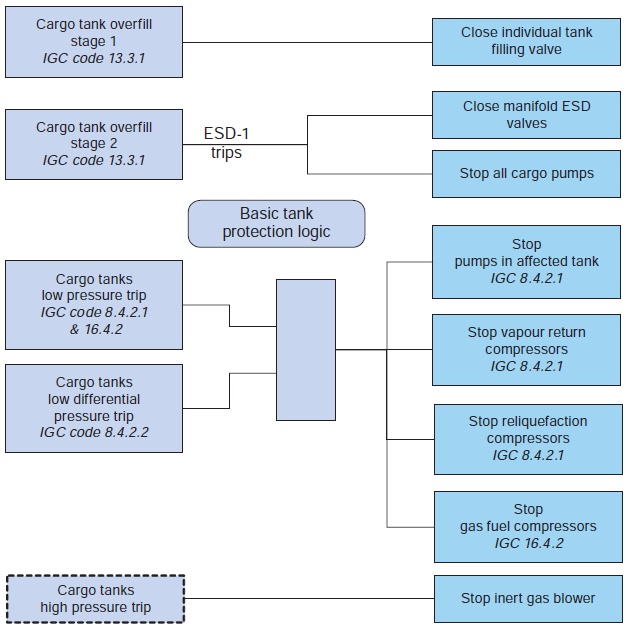
The diagram shows a high pressure trip. The necessity for such a trip will depend on the operating pressure and design of any inert gas plant installed. This trip will be set slightly below MARVS.
Gas Burning Safety System
A detailed treatise on these systems is outside the scope of this article and this point will just provide an overview, concentrating on the interface with the cargo system.
As the name implies, the purpose of this system is to protect the machinery spaces by closing off the gas supply under certain emergency conditions. Isolation of these spaces from the gas supply is achieved by tripping the master gas fuel valve, which is located in the cargo area. A basic requirement of the IGC Code is that there must be a manual trip point in the engine-room and automatic closure on ventilation failure or in the event of high gas concentration.
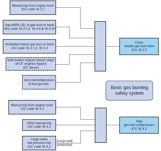
IGC 16.3.7 requires that the master gas fuel valve can be closed from within the machinery space and the more usual interpretation is that there should be a physical gas burning emergency trip «button» on the engine control console. It is recommended that this should be a self-latching device so that resetting requires a conscious and deliberate act. A hinged cover should be provided to reduce the likelihood of accidental operation.
It will be interesting: Personal health and safety crew members on board a gas carrier
IGC 16.4.2 requires that Gas Fuel Compressors «should be capable of being remotely stopped from a position which is always and easily accessible, and also from the engine-room». The latter is most easily fulfilled by using the same gas burning emergency trip device already described. As a core requirement of the fire control centre is that it is «always and easily accessible», this is an ideal location for the alternative gas fuel compressor trip point.
It is recommended that on detection of the master gas fuel valve leaving the full-open position, gas fuel compressors are automatically stopped and, on actual closure, the line downstream of the valve is automatically purged of gas by using nitrogen.
Unlike all other trips shown in this diagram, the purpose of the cargo tank low pressure trip is not for the safety of the gas burning system but for the cargo containment system.

- IMO, «International Code for the Construction and Equipment of Ships Carrying Liquefied Gases in Bulk» (IGC Code), 1993 as amended.
- IMO, «International Convention for the Safety of Life at Sea», 1974 – SOLAS, as amended.
- EN 1532 «Installation and equipment for liquefied natural gas – Ship to shore interface and port operations».
- EN 50020 «Electrical Apparatus for Potentially Explosive Atmospheres».
- SIGTTO, «Guidelines for Hazard Analysis as an Aid to Management of Safe Operations», 1992.
- SIGTTO, «Liquefied Gas Handling Principles on Ships and in Terminals», 3rd Edition 2000.
- SIGTTO, «Guidelines for the Alleviation of Excessive Surge Pressures on ESD», 1987.
- SIGTTO, «Recommendations and Guidelines for Linked Ship/Shore Emergency Shut-Down of Liquefied Gas Cargo Transfer», 1987.
- SIGTTO, «Accident Prevention – The Use of Hoses & Hard Arms».
- SIGTTO, «Ship Shore Interface – Safe Working Practice».
- OCIMF/SIGTTO «Recommendations for Manifolds for Refrigerated Liquefied Natural Gas Carriers (LNG)», 1994.
- MAIB report No. 10/2007 «Major LPG Leak from Gas Carrier Ennerdale».