Control Zones are an important topic in LNG Bunkering. For Safety, Security or Operation the need to establish control zones has been one of the important elements developed to mitigate the risks arising from potential hazardous releases of LNG or from the potential of external induce harm to LNG bunkering or small scale installations. Safely navigating the LNG bunkering Hazardous zone is crucial for ensuring the integrity of crew, equipment, and the environment during a liquefied natural gas fuel transfer.
This article addresses different control zones, seeking harmonization between existing international standards and industry guidance currently published. Both ISO/TS 18683 and ISO 20519 include a section on Safety Zones, in Annex, linked to Risk Assessment relevant provisions. The elements contained in both ISO documents are reviewed and taken as a departure point for the good practice suggested to PAAs in the present document.
Terminology used in this article will be directly consistent with ISO 20519, in particular to the number of control zones to be considered and their relative nomenclature.
In this article a generic overview is given, with the indication of the main relevant elements to consider in this context. Section “Hazardous Zone” is dedicated to Hazardous Zone, its definition, objectives, reference for the calculation of its extent, approval process and how to enforce it. The same approach is followed for both Safety Zone and Monitoring and Security area, respectively in articles Safety Zone“Safety Zone” and Security Zone“Security Zone”.
Read also: LNG (Liquefied Natural Gas) as Fuel
As a relevant initial note it is important to have in consideration, especially with regards to the Safety Zone definition, calculation, implementation and enforcement, the present Guidance does not prescribe distance values for any specific bunkering scenarios. Instead the path here followed is to advise on a good practice approach to PAAs evaluation and approval of Safety Distances. The core need for harmonization, in the interpretation given in this guidance document, is not for harmonized Safety Distance values but to a harmonized procedure for its evaluation and approval.
Controlled Zones in LNG Bunkering
Should an accidental loss of containment occur during LNG bunkering, LNG will be released and disperse under specific local conditions, subject to the intrinsic thermodynamic properties of LNG and to the dynamical behaviour of the LNG cloud. Once it achieves an air fuel mixture that will support combustion, it will burn when an ignition source is found. A safety zone designed to ensure that only essential personnel and activities are allowed in the area that could be exposed to a flammable gas in case of an accidental release of LNG or natural gas during bunkering shall be created. This annex provides guidance on the determination of that safety zone.
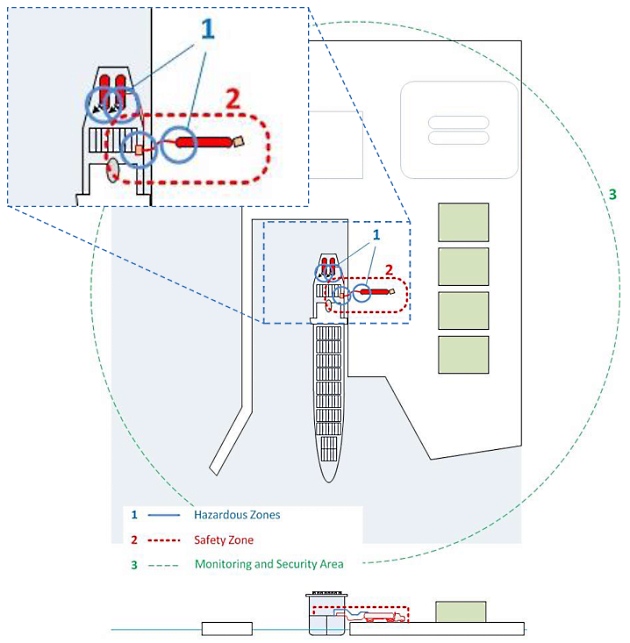
The safety zone will normally be inside the monitoring/security area and shall encompass hazardous zones defined by IEC 60079-10-1 or other relevant regulations. Figure 1 illustrates the relative location of the Safety Zone, the Hazardous Zone and Monitoring and Security Area related to the bunkering facility. The combined hazardous zones (including relief valve vent outlets) and safety zones for the LNG receiver and LNG provider shall be considered in the risk assessment, particularly if they are in the proximity of unsecured ventilation inlets.
The Monitoring and Security Area is a larger area that extends beyond the safety zone and is established to monitor vessel traffic and other activities that could be a threat during the bunkering operation, amongst other security relevant aspects. The monitoring and security area shall be established by the PAA, informed to the BFO and RSO. Other authorities, operators and intervening parts in the operational scenario should be well informed on the Security Area extent. Restricted areas within the port facility, required by the International Ship and Port Security (ISPS) Code, may constitute a portion of the monitoring and security area, however, are typically larger in extent.
The following Controlled Zones are defined in ISO/TS 18683 and EN ISO 20519 (figure 1, adapted from the ISO standards)
- Hazardous Zones.
- Safety Zone.
- Monitoring and Securing Area.
Sections “Hazardous Zone” to Security Zone“Security Zone” detail the relevant aspects relative to the Control Zones as presented. The graphical representation in figure 1 gives close reproduction to ISO diagram (figure B.1 in ISO 20519), with the three control zones defined represented in a generic way.
Recently SGMF has augmented the set of control zones from three to five, providing for a Marine Zone and an External Zone. The Monitoring and Security area is still considered according to ISO definition, added now with 2 extra monitoring zones.
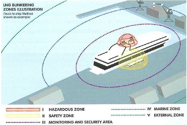
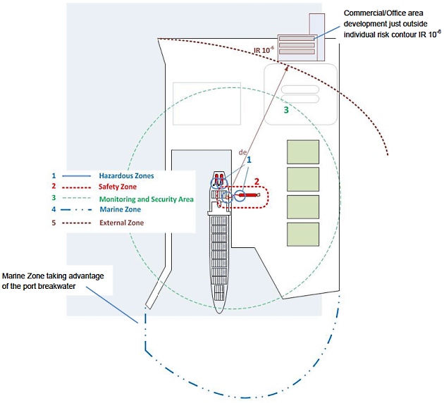
Definitions from SGMF are consistent with ISO for zones, with the three first, i) to iii), hazardous and safety zones and monitoring/security area, having the same definition. For the Marine Zone and External Zone, the new definitions for control zones brought by SGMF guidelines are illustrated in figure 2 and explained further in figure 3 below.
i. Hazardous zone: Three dimensional space where a flammable atmosphere may exist at any time.
ii. Safety Zone: three-dimensional area around the LNG transfer system determined from the result of a leak or emergency discharge of LNG or vapour return occurring. Exists during bunkering operation only.
iii. Monitoring and Security Area: an area around the LNG transfer equipment that needs to be monitored as a precautionary measure to prevent interference with the LNG transfer operation.
iv. Marine Zone: a zone of sufficient size to prevent passing shipping from impacting the LNG transfer operation.
v. External Zone: the distance to a defined risk level, frequently places where the public may be present as required by some regulatory regimes.
The relevance of bringing SGMF definitions together with ISO standard references (for both ISO/TS 18683 and ISO 20519) is related to the importance of understanding the control zones’ concept as a whole.
From 3 (three) ISO zones definition up to 5 (five) control zones in SGMF guidance, it should be important to establish the essential generic first principles that should be observed in all control zones determination:
- Define Control Zone;
- Check level of protection;
- Implement;
- Evaluate and, if, necessary;
- Re-define.
It will be interesting: Balancing Cleaner Fuel and Environmental Impact in LNG Emissions
- Bunkering parameters (pressure, temperature).
- Potential for excessive BOG generation.
- Weather factors (in particular wind).
- Other activities nearby (remarkably those involving also safety distances).
- Local infrastructure.
- Receiving ship characteristics.
- Implemented safeguards, resulting from risk assessment.
The diagram presented in figure 4, below, outlines a staged approach for the definition and implementation of Control Zones. In addition to the description of each stage, the responsibilities for each of the steps are also suggested as good-practice.
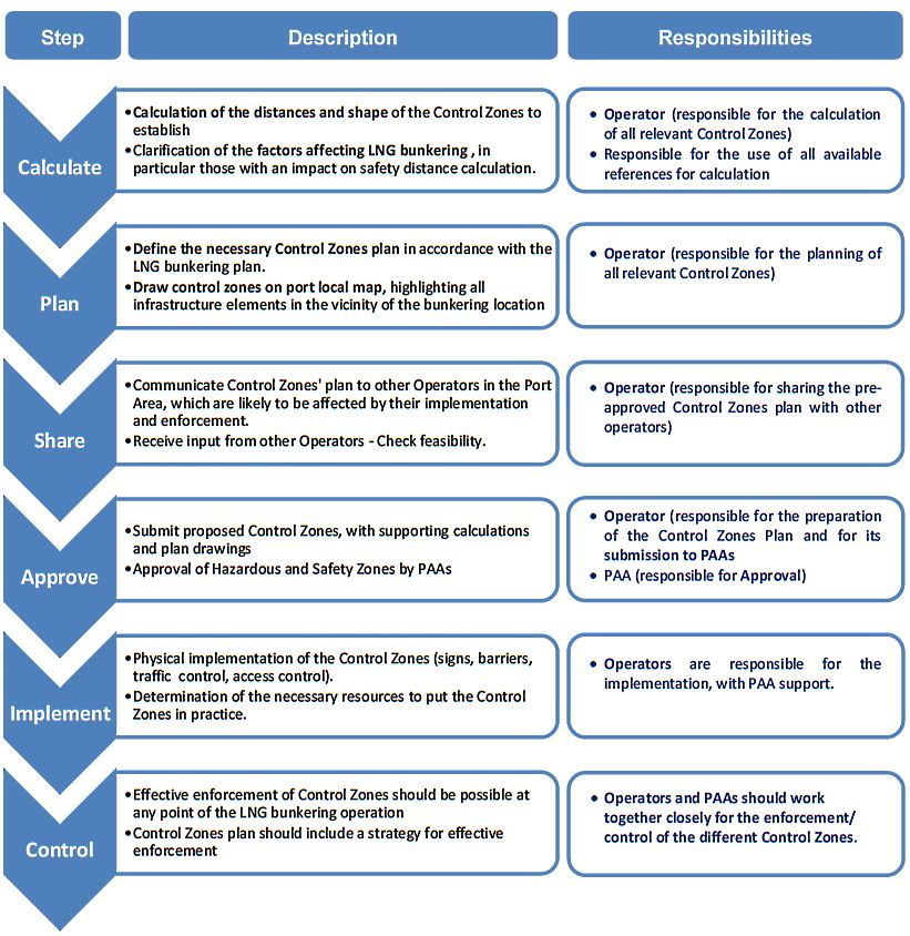
In addition to the first principles presented in the previous page, and to the general procedure suggested above, in the diagram of figure 4, the present Guidance Control Zones “minimum requirements” and “meaningful protection” should necessarily be considered together.
Minimum requirements will be derived directly from standards, direct/numerical calculations or modelling. References can be given for minimum required control zones and area definition.
Meaningful protection is based on the implementation of the minimum requirements, adding to it a critical iterative judgement of the situational scenario, infrastructure and local conditions at the time of LNG bunkering operation. This will be the concept further explored in section Concept of Meaningful Protection“Meaningful Protection”.
Hazardous Zone
References
The reference standard for the definition, calculation and implementation of Hazardous Zones is:
| IEC 60079-10-1:2015 – Explosive atmospheres – Part 10-1: Classification of areas – Explosive gas atmospheres | IEC | International Standard | Standard concerned with the classification of areas where flammable gas or vapour hazards may arise and may then be used as a basis to support the proper selection and installation of equipment for use in hazardous areas. It is intended to be applied where there may be an ignition hazard due to the presence of flammable gas or vapour, mixed with air. |
| adopted as European standard EN 60079-10-1 |
Other standards exist, remarkably the North-American:
- NFPA 497. 2012, Recommended practice for the classification of flammable liquids, gases or vapours and of hazardous (classified) locations for electrical installations.
- NFPA 70 – National Electrical Code (Informational Note: Although the scope of this Code indicates that the Code does not cover installations in ships, portions of this Code are incorporated by reference into Title 46, Code of Federal Regulations, Parts 110–113).
There are some significant differences between the American and European standards, especially with regards to the calculation approaches for Hazardous Zone area calculations.
Definition
Hazardous Zone is any three-dimensional envelope in which a flammable and/or explosive atmosphere may occur in quantities such as to require special precautions to protect the safety of workers, third- party personnel and material. Special precautions and measures for construction, installation and use of electrical apparatus should be followed, as given in IEC EN 60079-10-1.
Read also: The Role of LNG Bunkering Infrastructure
Hazardous zones related to installed equipment, LNG storage or other will be present even outside bunkering operations. They are design-related and a classification framework exists for the definition of different Hazardous Zone classes, corresponding to specific probability-frequency based criteria.
Objective
The objectives for Hazardous Zone implementation are:
- To allow the definition of adequate measures to mitigate fire and/or explosion risk in areas where a probability frequency for flammability/explosion conditions is known in advance.
- To develop the necessary safeguards against fire and explosion originated in know flammable atmosphere sources.
- Elimination of ignition sources in the classified areas.
- Minimization of the personnel involved in hazardous classified zones to the essential for safe operation.
- To restrict the use of electrical equipment to certified Ex-proof Ex-proof refers to a characteristic of electric equipment which conforms to the relevant IEC EN 60079 standard. Different protection types may apply, depending on the type of equipment.x equipment type. Different equipment will be subject to specific protection types Different protection types may be considered for different equipment classification.x (corresponding to different parts of IEC EN 60079.
- To allow for safe design even when the presence of flammable/explosive atmosphere cannot be completely eliminated.
Classification
Table 1, below, list the relevant Hazardous Areas, relevant in particular for LNG bunkering.
| Table 1. Hazardous Areas Classification | ||||
|---|---|---|---|---|
| Event | IEC EN 60079-10-1 IGC/IGF Definition (NFPA 70 Definition) | Frequency of Occurrence (from available literature) | Examples (for LNG Bunkering Scenario) | Reference distance |
| Zone 0: | Zone 0 | Explosive atmosphere for more than 1 000 h/year. | Inside the LNG Storage tank, of any type. Buffer storage tanks. | No applicable reference distance. Zones “0” are self- contained within tank boundaries. |
| An area in which an explosive gas atmosphere is present continuously or for long periods. | (Class 1 – Division 1) | |||
| Zone 1: | Zone 1 | Explosive atmosphere for more than 10, but less than 1 000 h/year. | Inside LNG bunkering transfer system (hose, transfer lines, transfer arm). Will only occur if inerting/purging haven’t been achieved successfully. This should happen both before and after bunkering. | No applicable reference distance. |
| An area in which an explosive gas atmosphere is likely to occur in normal operation. | (Class 1 – Division 1) | |||
| Zone 2: | Zone 2 | Explosive atmosphere for less than 10 h/year, but still sufficiently likely as to require controls over ignition sources. | Flanged connections for bunkering LNG transfer and vapour return Bunkering manifold groups. | Typically 3m around any of the equipment/systems/d esign features listed as example. |
| An area in which an explosive gas atmosphere is not likely to occur in normal operation and, if it occurs, will only exist for a short time. | (Class 1 – Division 2) | |||
Calculation
Calculation of Hazardous Zones is not a straightforward task. It is first important to underline the difference between Hazardous Zone and the Safety Zone:
- The Hazardous Zone will be a project characteristic, derived from the engineering judgement that “an explosive/flammable atmosphere will be present, at a given location, with a certain frequency of occurrence“;
- The Safety Zone, a different concept, will be the zone where dispersion of gas vapours are expected, following an incidental release of LNG.
Both zones may be compared with regards to the type of safeguard they provide, based on the estimation of a certain gas dispersion, with the flammability limits travelling over time and space, following leakage, spillage or any type of containment loss, either at flanges, connectors, overfilling, venting, PRV malfunction or any incidental breaches along the LNG bunkering line. The essential difference will be on the fact that Hazardous Zones will be present at all times, around equipment and elements where explosive/flammable atmospheres are expected with a certain frequency of occurrence.
Safety Distances are safeguards against an incidental unlikely event which, to achieve acceptable risk levels (qualitative or quantitatively perceived) must be in place. Elimination of ignition sources and mitigation of fire/explosion risks are the objective. Safety Distances are temporary in nature and are only present during LNG bunkering.
ISO/IEC Calculation
ISO/TS 18683 and ISO 20519 have no exact reference to the extent of hazardous zones, giving only indication that these are to be in accordance to IEC 60079-10-1 or other relevant regulations. In IEC 60079-10-1 a methodology is included for the calculation of Hazardous Zones, for both internal and external open-air locations. This methodology is firstly based in the determination of the Hypothetical Volume (Vz.), a parameter representing the volume over which the mean concentration of flammable gas or vapour will be either 0,25 or 0,5 times the LEL, depending on the value of a safety factor, k.
Methodology for hazardous zone estimation presented below.
The method developed allows the determination of the type of zone by:
- estimating the minimum ventilation rate required to prevent significant build-up of an explosive gas atmosphere;
- calculating a hypothetical volume, Vz which allows determination of the degree of ventilation;
- estimating the persistence time of the release;
- determining the type of zone from the degree and availability of ventilation and the grade of release using table B.1;
- checking that the zone and persistence time are consistent.
An important note is made in the standard, to the methodology developed:
In fact the objective of the methodology developed is to ultimately define the ventilation required for a given explosion-classified space. The standard emphasizes in this way that the hypothetical volume is not directly related to the size of the hazardous area, and stresses that for detailed recommendations regarding the extent of the hazardous areas in specific industries or applications, reference may be made to national or industry codes relating to those applications.
1 Determine the theoretical minimum ventilation flow rate of fresh air to dilute a given release of flammable material to the required concentration below the lower explosive limit:
where:
- (dV/dt)min – is the minimum volumetric flow rate of fresh air (volume per time, m3/s);
- (dG/dt)max – is the maximum rate of release at source (mass per time, kg/s);
- LELm – is the lower explosive limit (mass per volume, kg/m3);
- k – is a safety factor applied to the LELm; typically:
- k = 0,25 (continuous and primary grades of release);
- k = 0,5 (secondary grades of release).
- T – is the ambient temperature (in Kelvin, K).
NOTE: For converting LELV (vol %) to LELm (kg/m3), the following equation may be used for normal atmospheric conditions as given in 1.1;
2 The relationship between the calculated value (dV/dt) min and the actual ventilation rate within the volume under consideration (Vo) in the vicinity of the release can then be expressed as a volume (Vk).
where:
- C – is the number of fresh air changes per unit time (s-1) and is derived from:
where:
- dVo/dt – is the total flow rate of fresh air through the volume under consideration, and;
- Vo – the entire volume (within the control of the plant) served by the actual ventilation in the vicinity of the release being considered
3 Effective air exchange at the source of release will be lower than that given by C in equation (3), leading to an increased volume (Vz). By introducing an additional correction (quality) factor f to equation (2), the following is obtained
where:
- f is the efficiency of the ventilation in terms of its effectiveness in diluting the explosive gas atmosphere, with f ranging from f = 1 (ideal situation) to, typically f = 5 (impeded air flow).
4 Open-Air Vz estimation: In an open-air situation even very low wind speeds will create a high number of air changes. IEC 60079-10-1 uses the example of a hypothetical cube with side dimensions of 15 m in an open area. In the case presented a wind speed of approximately 0,5 m/s will provide an air exchange rate of more than 100/h (0,03/s) with volume Vo of 3 400 m3. In a conservative approximation using C = 0,03/s for an open-air situation, a hypothetical volume Vz of explosive gas atmosphere can be obtained by using the equation (5):
where:
- f – is a factor to allow for impeded air flow (see equation 4);
- (dV/dt)min – is as previously defined (m3/s);
- 0,03 – is the number of air changes per second.
The methodology presented has several limitations which are important to note:
- The methodology presented by IEC 60079-10-1 is derived for indoor gas release evaluations, with the ultimate objective to define ventilation requirements for given explosion-classified spaces.
- The calculation of a hypothetical volume Vz, relevant for ventilation requirements, is of little value for Hazardous Zone determination. The shape of the zone, its extent, the influence of external factors and other shape-defining elements are fundamental to determine the extent of the hazardous zone. Ultimately the large interest in the design of LNG bunkering operation will be in the determination of realistic zones, not theoretical volumes.
- Recognizing the need also to define an approximation to exterior open-air spaces, factors are used to introduce the physical fact that even small displacement of air in exterior space will promote quick dissipation of small leakages. These are however factors which have little adherence with physical behaviour and have been proved to result, in a large number of cases, in conservative volumes.
- Because dispersion is normally more rapid in an open-air situation as a result of the different dispersion mechanism, calculation proposed by IEC 60079-10-1 will generally result in an overlarge volume.
- Factor f. is determinant in the magnitude of results for Vz. A factor of empirical nature should not have such a determinant weight in the end result.
IGF/IGC Code
Hazardous Areas are defined for:
- The receiving ship in accordance with IGF Code, regulation 12.5;
- The bunkering ship in accordance with IGC Code, regulation 1.2.24.
In particular for the IGF Code, example minimum hazardous zone sizes include:
- Areas on open deck, or semi-enclosed spaces on deck, within 3 m of any gas tank outlet, gas or vapour outlet, bunker/supply manifold valve, other gas valve, gas pipe flange and gas tank openings for pressure release;
- Areas on the open deck within spillage coamings surrounding gas bunker / supply manifold valves and 3 m beyond these, up to a height of 2,4 m above the deck;
- Semi-enclosed bunkering stations, and;
- Areas within 1,5 m surrounding spaces listed above.
In the absence of a mandatory calculation methodology for the hazardous zones attained to LNG bunkering, and in view of the challenges for calculations following IEC 60079-10-1methodology for hypothetical volume, as presented in the previous section, a good practice approach may be established through the adoption of IGF/IGC Code Hazardous Areas reference, as listed above.
Figure 5, below, illustrates this application in a generic representation of a PTS LNG bunkering arrangement.
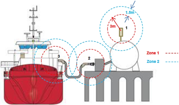
The bunkering-related hazardous area will include areas throughout the complete LNG bunkering system arrangement (truck, fixed installation ashore, bunkering manifold at the berth, etc.). Even though these areas are presented as fixed references, depending on the outcomes of the risk assessment and the specific details of the bunkering process (equipment and transfer flow rates and pressures) their size be increased.
The extent of the hazardous area classification zone, following the above approach, will be no more than about 4,5 m, being always less than the Safety Zone.
The advantage of following the references used for the IGF Code, or IGC Code, is that a common ground for harmonization can be established, to be followed by all involved in the LNG bunkering operation. It may however fail to be representative of actual on-site conditions, especially in special cases where multiple connections on a common bunkering manifold are used. The likelihood of leakages associated to fast-connect/disconnect may increase significantly. If purging/inerting are not fully achieved this will be even more likely.
It is important to confirm the relevance of the hazardous zones, they will dictate the specification for electrical equipment and also define the areas where other hazards may be present (such as asphyxiation, through oxygen depletion or low-temperature/cryogenic).
Meaningful protection is to be checked for the Hazardous Zones proposed for any given LNG bunkering arrangement. The approval exercise should be based on the verification of the operational aspects, main assumptions, pressure and temperature parameters, amongst other aspects referred in sections “Equipment for Hazardous Zones” and Concept of Meaningful Protection“Meaningful Protection”.
Computational Calculation
Having in mind the limitations recognized to the methodology prescribed by IEC 60079-10-1 alternative calculation methods are possible and often looked for to define the actual extent of Hazardous Zones.
Whichever calculation methodology is followed, from whatever valid code, the calculation of a volumetric release, based on mas flow rate for any given leak, will only result in a non-realistic arbitrary zone. As an alternative to this, Computational Fluid Dynamics (CFD) has more recently been applied In the case of small LNG vapour leakages CFD will be the computational tool to use. Model can be refined enough to capture the dispersion of the small leakages that are typically associated to the definition of hazardous zones.x, in the majority to substantiate some criticism to the IEC standard applicability to open-air applicability of Vz calculations. The use of CFD here, as in other areas of engineering, allows the integration of non- linear effects, such as turbulence, modelling of the terrain and environmental conditions, amongst other aspects. Figure 5, below, presents a possible graphical comparison which may potentially affect the definition of the hazardous zone and, consequently, the protection classification for equipment being used within Hazardous zone 1 (blue).
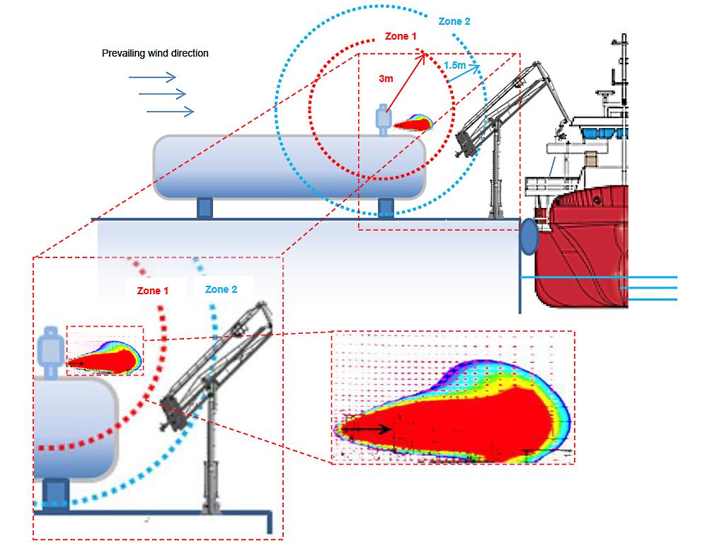
In figure 6 Zone 1 and 2 are indicated with a red and blue circle respectively. For the sake of simplicity only the hazardous zones around the type-C tank, from a generic fixed bunkering type installation.
CFD allows, in the presented figure, to verify that, not only the volume of released vapour is much smaller but that the extent of the hazardous zones is also going to be different. Should the assumptions for the CFD be accurate enough and the computational model sufficiently robust Only software which is either a commercial suite package (ANSYS CFX, FLUENT), or a demonstrated self-developed software should be considered acceptable. Verification & Validation procedures should apply to all models (as listed in article “Good Practice in Control Zones”).x a proposal for a smaller Hazardous Zone could be supported. This would reflect in the classification of nearby equipment, such as the crane represented in the generic example. The relation between the extent of the hazardous zone and the different equipment that can be allowed within those zones is the most important aspect regarding hazardous zones.
The quality of the CFD model, the assumptions made, the grid refinement, convergence study, amongst other aspects relevant for computational gas dispersion, should be the focus for PAAs evaluation, as detailed in article Control Zones“Good Practice in Control Zones”.
Equipment for Hazardous Zones
As indicated in the previous section, in the hazardous area, only electrical equipment certified in accordance with IEC 60079 is permitted. Other electrical equipment should be de-energised prior to the bunkering operations. Attention is drawn to the following equipment, which is not intrinsically safe and should therefore be disabled, except if otherwise justified:
In Hazardous Zone, the principle of ignition sources mitigation dictates that only specialy protected, and certified, equipment should be used within those zones.
The equipment category indicates the level of protection offered by the equipment.
Category 1 equipment may be used in zone 0, zone 1 or zone 2 areas.
Category 2 equipment may be used in zone 1 or zone 2 areas.
Category 3 equipment may only be used in zone 2 areas.
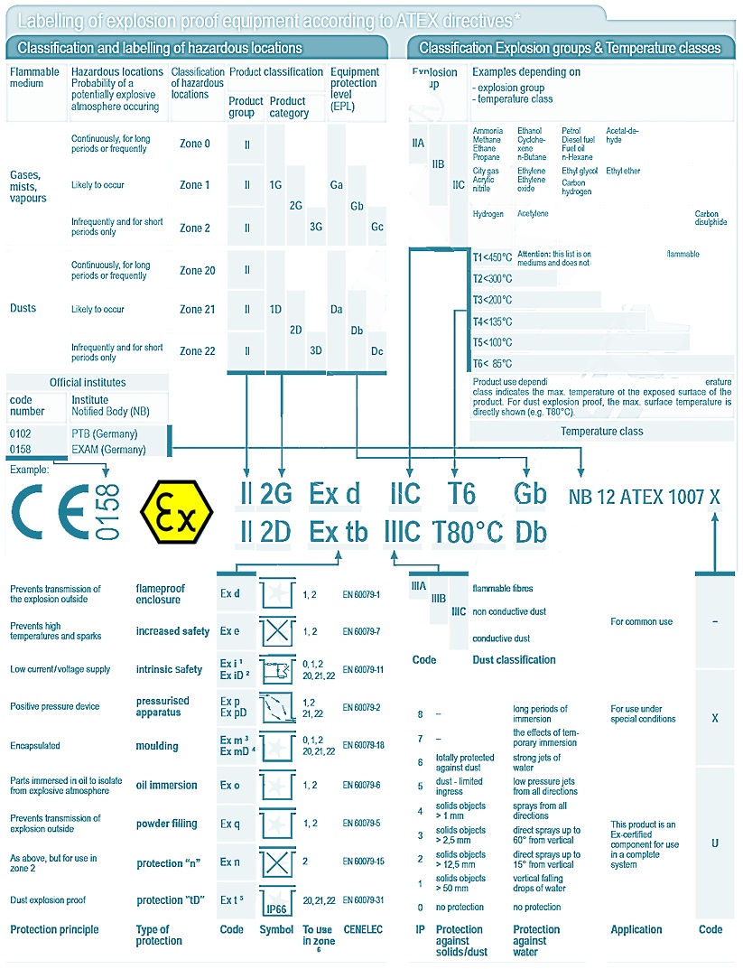
All equipment certified for use in hazardous areas must be labelled to show the type and level of protection applied, conforming with the relevant parts of IEC 60079.
In Europe the label must show the CE mark and the code number of the certifying body (Notified Body). The CE marking is complemented with the Ex mark, followed by the indication of the Group, Category and, if group II equipment, the indication relating to gases (G) or dust (D).
For example: Ex II 1 G (Explosion protected, Group 2, Category 1, Gas) Specific type or types of protection being used will be marked.
- Ex ia IIC T4. (Type ia, Group 2C gases, Temperature class 4).
- Ex nA II T3 X (Type n, non-sparking, Group 2 gases, Temperature class 3, special conditions apply).
Table 2, below, lists the minimum protection categories for Gas hazardous zones:
| Table 2. Minimum protection requirements for Gas Hazardous Zones | ||||
|---|---|---|---|---|
| Group | Ex-risk | Zone | EPL | Minimum type of protection |
| II (gas) | explosive atmosphere > 1 000 hrs/yr. | 0 | Ga | ia, ma |
| Explosive atmosphere between 10 and 1 000 hrs/yr. | 1 | Gb | ib, mb, px, py, d, e, o, q, s | |
| Explosive atmosphere between 1 and 10 hrs/yr. | 2 | Gc | n, ic, pz | |
Table 3, below, presents the wider equipment classification chart, as adapted from ATEX. Chart to be used for verification of equipment certification and confirmation of their use within LNG bunkering hazardous zones.
Approval
Approval of Hazardous Zones is of the responsibility of the PAA during the evaluation of the project proposal, in the course of the permitting process.
The following elements should be checked for approval of Hazardous Zones by PAAs:
1 Identification of all Hazardous Areas in suitable diagrams/plans where the whole LNG bunkering system is represented. Zones 1 and 2 should be clearly identified and related to the following elements in the bunkering system:
a Bunkering manifolds, their flanged connections or containment coamings.
b Flanged connections along the bunkering line.
c Venting lines, GCUs.
d ERC.
e QC/DC bunkering connectors.
f Any flanged connection along the bunkering transfer system.
g Bunkering articulated arms, in particular where swivel LNG piping joints are present, mechanical elbows and other articulated connections.
2 Identification of the references for each Hazardous Zone presented. One or more of the references below should be presented:
a IEC 60079-10-1, indicating which assumptions were followed for the definition of the Hazardous Zone extent.
b IGF/IGC Code, making reference to the code, in particular indicating pressure and temperature windows defined for the bunkering. The reasoning behind this note is, in particular, relevant to check compatible physical p-t conditions between LNG delivered and LNG.
c Other Codes, in particular if national/regional standards have been followed, other than IEC/EN related.
d CFD, identifying the responsible person for the calculations, the code used, assumptions followed, verification & validation procedures, including convergence of model, mesh refinement location, boundary conditions.
3 LNG Bunkering management Plan, to be checked for reference to Hazardous Zones, in particular provisions for its establishment and control. Only if a projected Hazardous Zone is proposed, along with effective measures for its control, it should be considered realistic. Sign, labelling and warning signs are some of the physical measures possible. Also confirmation keys, unlocked following Ex-proof verification can be considered.
Enforcement
Enforcement of Hazardous Zones should be done during in-service inspection of LNG bunkering facilities for Ex-proof confirmation of the whole inventory of electrical equipment used.
To support in this task, PAAs should request to operators a full updatable inventory for Ex-proof equipment, consisting of a list of electrical equipment that can subject to verification/check for Ex-proof conformity. Only electrical equipment contained in that list should be present in operation. Other potential ignition sources, other than electrical equipment should be looked for.
Read also: LNG Bunkering Guide – What It Is and How to Use It
Upon any finding which may raise concern regarding to insufficient ignition source mitigation, the LNG bunkering operation should be halted until the findings are resolved.
In-service inspections for Control Zone enforcement should be conducted with minimum impact in the planned course for the LNG bunkering operation, not leading to unnecessary undue delays to all operators involved.

- Study on the completion of an EU framework on LNG-fuelled ships and its relevant fuel provision infrastructure, LOT 1 Position paper: Towards harmonized EU LNG bunkering guidelines, DNV-GL, 2016.
- Study on the completion of an EU framework on LNG-fuelled ships and its relevant fuel provision infrastructure, LOT 1 Final Report, DNV-GL, 2016.
- LNG Bunkering Guidelines IACS Recommendation n. 142, on LNG Bunkering, IACS, 2016.
- ISO/TS 18683:2015. (15-Jan. 2015). Guidelines for systems and installations for supply of LNG as fuel to ships. Technical Specification.
- Society for Gas as a Marine Fuel (SGMF). (2015). Gas as a marine fuel, safety guidelines, Bunkering. Version 1.0, February 2015.
- ISO 20519:2017. Ships and marine technology – Specification for bunkering of gas fuelled ships. (International Standard).
- IEC 60079-10-1. (2015). Explosive atmospheres – Part 10-1: Classification of areas – Explosive gas atmospheres.
- Directive 1999/92/EC – ATEX of the European Parliament and of the Council of 16 December 1999 on minimum requirements for improving the safety and health protection of workers potentially at risk from explosive atmospheres (15th individual Directive within the meaning of Article 16(1) of Directive 89/391/EEC).
- API RP-500. 1997. Recommended practice for classification of locations for electrical installations at petroleum facilities classified as CIass 1, Division 1 and Division 2. Washington. D.C: API.
- API RP-505. 1997, Recommended practice for classification of locations at petroleum facilities classified as Class I, Zone 0, Zone 1 and Zone 2. Washington, D.C. API.
- NFPA 497. 2012, Recommended practice for the classification of flammable liquids, gases or vapours and of hazardous (classified) locations for electrical installations in chemical process areas. Quincy, MA: NFPA.
- IEC EN 60079-10-1 Ed.1.0, 2008. Electrical apparatus for explosive gas atmospheres – Part 10-1: Classification of areas – Explosive gas atmospheres. International Electrotechnical Commission.
- Commission Decision 2010/769/EU of 13 December 2010 on the establishment of criteria for the use by liquefied natural gas carriers of technological methods as an alternative to using low sulphur marine fuels meeting the requirements of Article 4b of Council Directive 1999/32/EC relating to a reduction in the sulphur content of certain liquid fuels as amended by Directive 2005/33/EC of the European Parliament and of the Council on the sulphur content of marine fuels (OJ L 328, 14.12.2010, p. 15).
- USCG CG-OES Policy Letter 02-14 – Guidance Related To Vessels And Waterfront Facilities Conducting Liquefied Natural Gas (LNG) Marine Fuel Transfer (Bunkering) Operations.
- ADN – European Agreement concerning the International Carriage of Dangerous Goods by Inland waterways (Update version ADN January 2017).
- ADR – European agreement concerning the International Carriage of Dangerous Goods by Road (Update version ADR January 2017).
- Rhine Vessel Inspection Regulations (RVIR).
- EU general risk assessment methodology (Action 5 of Multi-Annual Action Plan for the surveillance of products in the EU (COM(2013)76) – Document 2015-IMP-MSG-15 – 16 October 2015.
- Safety Study, Chain analysis: Supplying Flemish ports with LNG as a marine fuel, Analysis of safety aspects, June 2012.
- EN 1160 – Installations And Equipment For Liquefied Natural Gas – General Characteristics Of Liquefied Natural Gas, NBN, 1st edition, August 1996.
- ESD Arrangements & Linked Ship/Shore Systems for Liquefied Gas Carriers, SIGTTO First Edition 2009 – SIGTTO.
- M. Kofod & S. Hartman, T. Mundt – Review of Recent Well-to-Wake Greenhouse Gas Studies evaluating the use of LNG as a marine Fuel, IMO MEPC/INF.15.
- LNG Access Code for Truck Loading for The Zeebrugge LNG Terminal – Based on version approved by the CREG on September 19th 2013 – Applicable as of January 1st 2014 – FLUXYS.
- Guidance for the Prevention of Rollover in LNG Ships – SIGTTO – First Edition 2012.
- Wang, Siyuan & Notteboom, Theo – The role of port authorities in the development of LNG bunkering facilities in North European ports, 14 January 2015, World Maritime University 2015.
- Verhoeven P (2010) A review of port authority functions: towards a renaissance? Marit Policy Manag 37:247-270.
- Society for Gas as a Marine Fuel (SGMF). (2017). Gas as a marine fuel, safety guidelines, Bunkering. Version 2.0, February 2015.
- COM(2003) 515 final – Communication from The Commission concerning the non-binding guide of good practice for implementing Directive 1999/92/EC of the European Parliament and of the Council on minimum requirements for improving the safety and health protection of workers potentially at risk from explosive atmospheres, Brussels, 25.8.2003.
- Davies, P. (2016) – Bunkering LNG: Setting the Safety Zone, 7th Motorship Gas Fuelled Ships Conference, November 2016.
- International Association of Oil & Gas Producers. (1-Mar 2010). Risk Assessment Data Directory – Process Release Frequencies. Report No. 434 – 1, 1 March 2010). Pertinent data from this report is summarised in: Davies & Fort, (Sept 2012), LNG as Marine Fuel – Likelihood of LNG Releases, Journal of Marine Engineering and Technology.
- PGS2 – TNO Yellow Book – Methods for the calculation of physical effects, due to releases of hazardous materials (liquids and gases) – CPR 14E (3rd Edition, 2005) – TNO – The Netherlands Organization of Applied Scientific Research.
- OECD Guiding Principles for Chemical Accident Prevention, Preparedness and Response, Guidance for Industry (including Management and Labour), Public Authorities, Communities, and other Stakeholders – 2nd Edition (2003) – OECD Environment, Health and Safety Publications.
- DNVGL-RP-G105 Edition October 2015 – Development and operation of liquefied natural gas bunkering facilities, Recommended Practice, DNV GL, 2015.
- USCG CG-OES Policy Letter No. 01-17 – Guidance for Evaluating Simultaneous Operations (SIMOPS) during Liquefied Natural Gas (LNG) Fuel Transfer Operations.
- LGC NCOE Field Notice 01-2017 – 14-Aug-17 – Recommended Process For Analysing Risk Of Simultaneous Operations (SIMOPS) During Liquefied Natural Gas (LNG) Bunkering.
- An Overview of Leading Software Tools for QRA, American Society of Safety Engineers – Middle East Chapter (161), 7th Professional Development Conference & Exhibition, March 18-22, 2005.
- Walter Chukwunonso Ikealumba and Hongwei Wu (2016) Some Recent Advances in Liquefied Natural Gas (LNG) Production, Spill, Dispersion, and Safety School of Chemical and Petroleum Engineering, Curtin University.