This article takes a deep dive into the entire picture of LNG emissions. We’ll explore its powerful role as a cleaner fuel while meticulously breaking down the strategies and best environmental practices needed to curb methane slip and other related emissions. This includes everything from the intricacies of bunkering interfaces and land-based logistics, to the specifics of small-scale fixed stations and vast pipeline networks. Ultimately, truly understanding and mastering these emissions isn’t just important-it’s absolutely essential to unlock LNG’s full potential as a sustainable fuel for a genuinely greener future.
- LNG as a Cleaner Alternative Fuel for Shipping
- Well-to-Wake GHG Emissions of LNG
- Methane Release Mitigation
- Scope
- LNG Bunkering Interface
- LNG Trucks
- LNG Bunker vessels and barges
- Small Scale Fixed LNG bunkering Stations
- LNG ISO containers
- Intermittent flow applications
- LNG Pipelines
- Good Environmental Practice for LNG Bunkering
- General
- Methane Release Mitigation
- Environmental Management Systems
The impact of using LNG as fuel for transport can be regarded from 2 different perspectives:
- the net benefits of LNG as a replacement of oil fuels, in terms of local air pollution (SOx, NOx and Particulate Matter); and
- the higher GHG emission potential of Methane (higher constituent of LNG).
On one hand these promising environmental benefits have already granted to LNG a front-run position as an alternative fuel Alternative fuels, as scoped and defined in Directive 2014/94.x, but, on the other hand, the concerns with regards to the actual GHG life-cycle benefits of Natural Gas, as LNG as fuel, are still today in discussion, deserving significant attention and underlining the need to develop adequate mitigating measures. The challenge is to potentiate the benefits of using LNG as fuel, whilst reducing the potential negative environmental effects from its use.
LNG as a Cleaner Alternative Fuel for Shipping
LNG does not contain sulphur, which results in (almost) no SOx emissions and almost no PM-emissions. In addition, because LNG has a higher hydrogen-to-carbon ratio in comparison to conventional fuels, the specific CO2 emissions are lower.
It is possible to obtain different potential gains, both in terms of GHG and the emission of other relevant substances, depending on which source of information you use. It is therefore important to identify and understand the conditions and assumptions contributing to the mentioned environmental benefits. Table 1, below, show the different The Controlled Dispersion of Liquid Spill and Vapour Emission Incidents by Water Spraypotential emissions reductions which can be achieved by using LNG as an alternative fuel.
| Table 1. Environmental benefits from the use of LNG as Fuel by Ships | ||
|---|---|---|
| Emission | Potential Reduction with LNG as Fuel (compared to HFO) | Observations |
| SOx | 95 to 100 % reduction | Compliance with sulphur regulations. |
| Some % of sulphur oxide emissions due to the use of pilot-oil fuels in dual-fuel operation. | ||
| Lean gas burn result in near-zero emission of sulphur-oxides. | ||
| NOx | Between 40 and 80 % | Depending on Engine technology. |
| Lean Gas burn Otto Cycle (low-pressure injection) – compliant with IMO Tier III (80-85 % NOx emission reduction). | ||
| Dual-Fuel Diesel Cycle (high-pressure injection) – not inherently Tier III compliant – will typically require additional NOx abatement device. | ||
| PM | 90-100 % | Some % of PM emissions due to the use of pilot-oil fuels, in dual-fuel operation. |
| Lean gas burn result in near-zero emission of sulphur-oxides. | ||
| CO2 | 25-30 % | Benefit for EEDI and EEOI indexes. |
| GHG (Well-to-Wake) | 0-25 % | From a “well-to-wake” perspective the GHG benefits from LNG as fuel are only effective if methane emissions to the atmosphere are adequately controlled and minimized. |
As it can be seen from the table above, the benefits from using LNG as fuel are indeed very significant with an almost complete reduction of sulphur oxide emissions and PM, and with a very significant reduction of NOx emissions. With regards to the reduction on direct combustion CO2 emissions to the atmosphere, the figure (up to 30 %) is also relevant but of lesser expression.
The following factors need to be taken into account when interpreting and discussing the potential benefits of LNG as fuel for shipping:
- Engine technology (dual-fuel, lean burn spark-ignited and Diesel-gas), with a special attention to pilot fuel percentages potentially used and their effect on the overall.
- LNG quality and composition.
- Life cycle analysis of LNG fuel, taking into account Natural Gas source, production, liquefaction, transportation/distribution chain and overall propulsive efficiency of a given ship.
Even though LNG is, undisputedly, a cleaner alternative fuel to heavy, diesel and distillate oils, it is worth pointing out that it is still a fossil fuel. Exploration, processing and all the life cycle of Cargo Related Spaces on Liquefied Natural Gas Carriersnatural gas throughout the possible fuel treatment, industrial and logistic processes and, finally, consumption, have to be taken into account in assessing LNG’s actual environmental impact.
Read also: Emergency Management and Methods of Handling Sudden or Unexpected Situations
A disadvantage of LNG is the potential increase in methane emissions (CH4). Methane slip, and other releases, can represent a serious problem, since methane has high global warming potential; methane leakages seriously affect the GHG reduction potential.
LNG as fuel can, therefore, represent a clear advantage with regards to local air quality improvement, with very significant expression in reduction of pollutant air emissions, but also the potential for methane emissions to the atmosphere, affecting thereon the GHG benefits from direct combustion CO2 reduction.
Well-to-Wake GHG Emissions of LNG
LNG can be regarded from a life cycle perspective and, in this particular case, it is important to note, not only the effects of producing LNG and transporting it over large distances by ship, but also the potential impact that methane emissions can have on LNG as fuel GHG reduction potential. This later approach is commonly known as “Well-to-Wake” analysis, as an adaptation of the approach already followed.
Important factors contributing to the WtW approach, contributing to LNG GHG footprint as ship fuel:
- CO2 emissions resulting from energy spent extracting, transforming, liquefying, transporting and distributing LNG.
- CH4 emissions resulting either from methane release events throughout the LNG life cycle and logistic chain.
CO2 emissions throughout the production and logistic chain are virtually impossible to avoid. They are in fact to be accounted for all fuels, not only LNG. Depending on the origin, type and age of liquefaction plants, distance travelled by LNG carrier vessels and, indeed, also on the smaller scale distribution footprint, the total actual GHG contribution will be different. LNG sourced from local natural gas production will therefore have a smaller carbon emission footprint than that sourced from a distant point in the globe. These considerations are however outside the scope of this Guidance.
Methane (CH4) is another gas of particular interest from a life cycle, well-to-wake perspective. Being 20-25 times more powerful than CO2 as a greenhouse gas during a 100 year time span, any release of methane to the atmosphere has the potential to reduce significantly the relevance of LNG as a shipping fuel.
Methane release can occur during all stages of the LNG life cycle. The particular case of methane emissions resulting from internal engine combustion is called “methane slip”. Incomplete gas combustion, leading to the emission of small amounts of methane to the atmosphere, contributes negatively to the environmental impact of LNG. There has been significant pressure to optimize four-stroke dual-fuel engine technology with design improvements to minimize methane-slip. In modern two-stroke engines this problem has practically been eliminated.
Whilst addressing the life cycle approach applied to LNG (Liquefied Natural Gas) as FuelLNG as fuel for shipping, the following aspects are identified as having the potential to further improve the accuracy of WtW results:
- Upstream methane release estimates (production, liquefaction and distribution), having integrated up-to-date research in the industrial production/processing of LNG.
- Engine Technology – considering new and emerging dual-fuel engine technology on both two-stroke and four-stroke diesel engines, focusing on efficiency and methane slip mitigation/reduction.
- Environmental impact of producing low-sulphur fuel oils (LSFOs) – identifying the relative GHG impact of oil fuel desulphurization, using the results as further evidence of the advantages of LNG.
- Comparative new technologies other than LNG – in particular scrubbers, identifying the additional energy consumption of such systems as an argument for using LNG rather than fuel oils.
The carbon emission factor of LNG (actual CO2 emissions from burning LNG as fuel) is approximately 25 % less than Common Hazards and Risk Assessment in Oil and Gas Industrymarine diesel oil (see table below). This is the result of its lower carbon presence at molecular level.
| Table 2. Combustion Factors for Diesel, in comparison to LNG | ||
|---|---|---|
| Fuel | Combustion Emission Factor gCO2/MJ LHV | Percentage reduction, % |
| Diesel | 75 | 0 |
| LNG | 56,1 | -25 |
The Well-to-Wake approach takes the analysis onto a more comprehensive scale, looking at each of the fuel’s life cycle stages. The figure below presents a rough comparison between WtW values of LNG compared to those of MDO. The main assumptions of the comparison are the carbon emission factors presented above, in t, an engine efficiency of 50 % as well as the methane slip reference value which takes into account more recent developments in 2-stroke, diesel cycle, low speed engines and 4-stroke higher speed Dual-Fuel-Electric LNG Carrier Propulsiondual fuel engines. The values that were used are rough and indicative that LNG causes approximately 20 per cent less CO2 emissions than MDO (if methane slip is not considered). A more modest benefit of 10 % would result if methane slip were to be considered, as shown in the diagram below.

In the particular context of the present Guidance the WtW considerations for CO2 emissions from LNG as Fuel are relevant as a measure indication on how important are LNG handling, distribution, transfer and bunkering operations in the port area. Having an appropriate production and distribution architecture in place is also very important when considering the environmental footprint of LNG as fuel.
Environmental benefits of LNG suffer the potential risk of being outbalanced by a poor GHG performance if due consideration for the need to avoid methane emissions is not carefully and rigorously implemented throughout the whole LNG fuel value chain.
Methane Release Mitigation
Scope
For the purpose of the present Guidance the objective is to provide PAAs with a reference on best environmental practice in LNG Bunkering Guide – What It Is and How to Use ItLNG bunkering, allowing and promoting the use of LNG as fuel as a beneficial measure to improve local air quality, whilst addressing the risk of potential negative GHG (methane) emissions.
The Well-to-Wake (WtW) considerations made in section “Well-to-Wake GHG Emissions of LNG” were important to express the need to carefully address any potential release of LNG/NG (under any form) to the atmosphere, as an event directly representing an Basic Knowledge of Hazard Controlsenvironmental hazard, with direct negative impact as GHG emission.
It will be interesting: Principles of Shift Changeover Process and Why it is Important
The scope for the present Guidance is however not covering the full WtW width. Only the aspects related to LNG bunkering are covered (in all aspects from arrival to port until delivery to the receiving ship flange). The use of LNG onboard is not covered in the present guidance.
Methane Release Mitigation, the title of the present Section, is therefore defined as a set of technical and operational measures to reduce down to negligible amounts, in normal operational conditions, the release of NG24 Figure 2, below, indicates the scope of this Guidance for all considerations relative to methane release mitigation
In addition to the scope definition in figure 2, it is furthermore important to note:
- Present section of the Guidance is concerned with the environmental aspects of LNG/NG release. Safety concerns are addressed in article Assessing the Safety Risks of LNG Bunkering“Risk & Safety”. No Safety related hazardous scenarios are addressed in this section.
- All environmental best practice considerations are valid, in the present section, for normal operational condition.
- In Emergency situations the release of LNG vapours to the atmosphere may be inevitable, through the opening of Pressure Relief Valves (PRVs).
- All emitted methane fractions should be quantifiable and reported (even if in emergency) as part of specific operator reporting obligations.
The risk of methane release to the atmosphere is higher during LNG transfer operations (loading on/off an LNG truck, barge or Ship-to-ship LNG transfer operationsbunkering transfer), and whenever adequate LNG vapour management operations are not in place. Improving the LNG distribution, handling and transfer/Guidance on HAZID and HAZOP for LNG bunkering operationsbunkering procedures, in addition to the safety benefits, will also result in a more sound environmental practice.
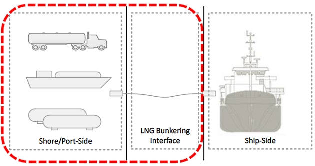
For the purpose of developing best practice in the particular aspect of methane release mitigation the present Guidance decomposes figure 2 into 2 separate dimensions:
- LNG Bunkering Interface, where mostly the interface operations are addressed, from flange to flange; hose connection to disconnection and;
- Shore/Port Side elements where, apart from bunkering transfer, also other aspects need to be considered regarding the small scale LNG development within the port area. These two dimensions are important for the development of a consolidated and practical best practice approach to the particular attention of PAAs.
Notwithstanding the fact that the LNG Fuelled Vessel (RSO) is not covered by the present Guidance it is important to underline that the receiving vessel will be expected to comply, as a minimum, with the IGF Code, in particular with paragraph Assessing the Safety Risks of LNG Bunkering“Tasks”, requiring the bunkering system to be so arranged that no gas is discharged to the atmosphere during filling of storage tanks. This is an important requirement for the receiving vessel that should, nevertheless, be extended to the whole bunkering scope, not only the filling of Accidents Involving LNG and LPG Storage Tanksstorage tanks. The same concern, and limitation, should be extended to the connection and disconnection procedures, including purging and inerting of bunker lines.
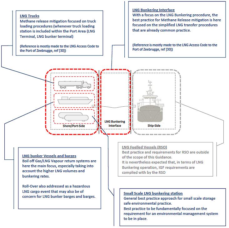
The filling of the RSO storage tanks will require consideration for LNG vapours to be adequately managed, but other moments of the LNG bunkering transfer procedures should also be accounted for when establishing a full evaluation of the potential environmental risks from bunkering related methane emissions.
LNG Bunkering Interface
Methane release mitigation in the LNG bunkering interface is directly related to the implementation of sound operational procedures. In fact, whereas technical measures for LNG vapour management can be implemented on Bunkering risk on Liquefied natural gas ships assessment and safety zonesLNG bunker vessels or bunker stations, or even on the receiving vessel, the interface, hose handling, purging, draining and inerting, are operations which are very dependent on training and experience, clear procedures and streamlined bunkering operation.
Read also: Liquefied Natural Gas as the Energy of the Future
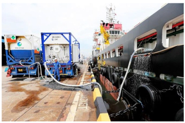
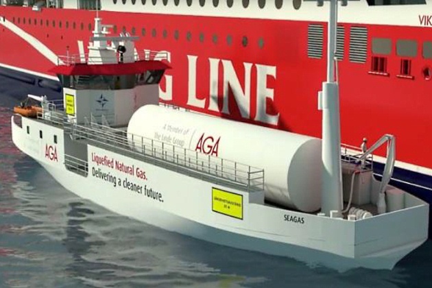
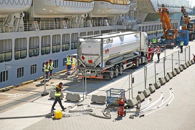
Regardless the LNG fuel source, from trucks, bunker vessels, barges or fixed bunkering stations, LNG bunkering presents similar challenges and procedure aspects. Inerting of bunkering lines, purging, cool-down procedures and draining, are similar, both in functional and technical aspects for all bunkering modes. LNG bunkering from trucks has been however the LNG bunkering mode where the largest share of experience has been gained in the last years, corresponding to the uptake in the learning curve regarding LNG bunkering. Figures 4 and 5, below, illustrate two different operational situations where LNG trucks are used.
1 – The ability of the vessel to cope with BOG pressure; 2 – BOG management system on vessels side; 3 – LNG spraying on vessel side to cool-down BOG
Whilst article Process Map & Organization of the LNG Bunkering“Proccess Map & Organization” and Strategies for Effective LNG Bunkering Operations and Their Execution“Bunkering Operation” of the present Guidance address the LNG bunkering process and organization in more detail, the present section seeks to identify the moments in the LNG bunkering procedure where the risk of methane release is higher, suggesting measures to mitigate that risk.
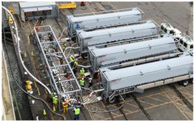
Fig. 5 LNG trucks in simultaneous multiple connection for LNG bunkering. Increasing volumes and rates of LNG Bunkering will also represent additional LNG vapour to manage. It is important to have a clear agreed procedure on how will LNG vapour be dealt with during bunkering
The diagram/table in figure 6 illustrates how the different stages of a simplified LNG bunkering procedure/operation relate to different potential risks of methane emission. From the connection of the hoses to their disconnection, in the end of the operation, it is important to understand in which moments of the operation the risk of methane release is likely to be higher and to consequently develop measures that are able to mitigate this risk.
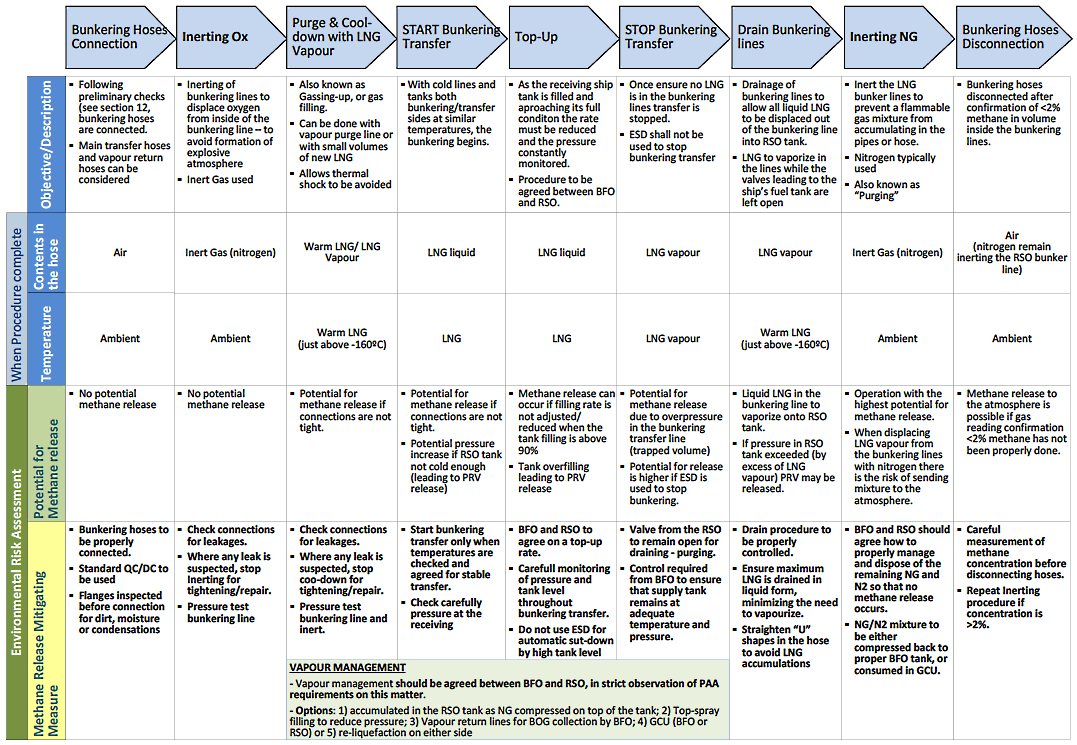
The following stages of a simplified LNG bunkering process are considered in figure 6:
- Bunkering Hoses connection;
- Inerting (for oxygen depletion);
- Purge and Cool-down with LNG Vapour;
- Start Bunkering transfer;
- Top-up;
- Stop Bunkering transfer;
- Drain Bunkering lines;
- Inerting (for natural gas purging);
- Bunkering Hoses disconnection.
LNG Trucks
Table 3, below, includes some of the LNG truck potential causes for operational related methane release. Both loading and off-loading are included. Technical and operational measures are presented for corresponding risk reduction.
| Table 3. LNG Truck – Methane release mitigating measures | |||
|---|---|---|---|
| LNG Bunkering/LNG small Scale supply chain | Potential release scenario | Methane Release – Risk mitigating measures | |
| Technical | Operational | ||
| LNG Trucks | During filling, onsite, at small scale LNG storage installation. Release of LNG vapour may occur if no adequate BOG management scheme/system is implemented. | LNG spraying possibility to cool LNG vapour on top of the tank. | Monitor Pressure and Temperature |
 | LNG trucks to be fitted with economizer | Top and Bottom filling | |
| Holding time in the LNG truck trailer tank is limited. As the LNG ages inside, BOG generates and increases pressure. Release of LNG vapour may occur if MARVS is exceeded. PRV will open to relief pressure. | Adequate insulation to increase holding time. | Plan to avoid waiting times while loaded | |
| Limit the use of single-walled LNG trailer trucks | |||
| LNG spraying possibility to cool LNG vapour on top of the tank. | |||
| If the tank is not in Cold condition (BOG temperature < 120 °C) filling with new LNG will generate excessive BOG. Release of LNG vapour may occur if MARVS is exceeded. PRV will open to relief pressure. | Provide technical means to cool-down with own LNG or Inert Gas/Nitrogen | Plan for LNG loading in cold condition (either LNG or Nitrogen) | |
| Avoid waiting times in warmer tank temperatures. | |||
| Filling-rate should be adequate above 90 % filling, for top-up of the LNG tank in the trailer truck. Inadequate filling rate for the top-up may result in LNG truck overfilling. | LNG tank levels monitot | Agree on adequate plan for top-up filling to avoid over-pressure in vapour side and MARVS exceedance. | |
| LNG pressure monitor | |||
| (Loading) | Adequate filling rate control mechanism at LNG truck filling station | ||
| LNG Trucks | For bunkering transfer LNG trucks can use pressure-buil-up units to transfer LNG to RSO by increase in Vapour pressure on top of the tank. If MARVS pressure is exceeded during pressure build-up PRV valve will open to relief pressure. | LNG pressure monitor | Adequate operating procedure for LNG transfer by pressure build-up |
 | LNG regulator before pressure build-up unit. | ||
| Malfunction and alarm conditions will lead to ESD actuation in RSO If ESD not fully compatibe with LNG truck system there is the risk that following the RSO bunkering valve is shut pressure will build-up in the bunkering line (and in the truck LNG tank). Release of LNG vapour may occur if MARVS is exceeded. PRV will open to relief pressure. | Fully compatible ESD to be used between LNG tank truck and | Adequate procedures to be in place to avoid excessive BOG generation and methane release, following bunkering stop. | |
| Adequate pressure monitoring to ensure no excess BOG is generated in the LNG truck tank after bunkering has been ESD-stopped. | |||
| Include back-pressure regulator into the circuit (regulated above operating pressure and below MARVS). | |||
| During LNG bunkering, if receiving tank is warmer there will be excessive BOG generation. If Truck receives return LNG vapour this will result in pressure increase in the truck tank. Release of LNG vapour may occur if MARVS is exceeded. PRV will open to relief pressure. | Proper tank equalization needs to be ensured prior to LNG fuel transfer. | Ensure adequate pre-bunkering procedures to be followed by BFO and RSO. | |
| Cool-down of receiving tank and bunkering lines needs to be ensured with the minimum LNG vapour possible. | Condition prior to bunkering to be carefully checked. | ||
| If draining/purging/inerting procedure is not adequately performed there is the possibility that some LNG/NG will remain in the bunkering line. Release of LNG vapour may occur if bunkering hoses are disconnected with LNG/NG still in some point of the line. | Gas measurement to be performed before hose is disconnected. | Ensure draining is effective. | |
| (Off-loading – Bunkering) | Avoid formation of “U” shapes where LNG can lay arrested. | Check for the existence of exterior ice cap (as an indicator for the presence of LNG inside the line) – heat up with water. | |
All the measures presented in table 3, above, are of operational relevance and can also be referred to article Strategies for Effective LNG Bunkering Operations and Their Execution“Bunkering Operation” of the present Guidance – Bunkering Operation. Notwithstanding the fact that the listed events and measures presented are also important for Safety purposes, it is here important to make note that an adequate environmental best practice approach should be the right frame for the methane release mitigating measures presented.
It is assumed that maintenance (both planned and condition-based) is appropriate for the truck LNG bunkering equipment (including tank, piping, PRVs, LNG pump and monitoring equipment/sensors).
Read also: Project Management of the Large-Scale Liquefied Natural Gas Facilities
For more operational related aspects related to LNG vapour management (BOG management) reference is made to article https://sea-man.org/lng-bunkering-operation.html#bunkering-procedure.
LNG Bunker vessels and barges
The main difference between bunker barges and vessels, when compared to LNG bunker trucks, are the higher capacities and bunkering transfer rates possible. With higher volumes of LNG stored onboard, and higher transfer rates, also the amount of LNG vapour to be accounted for is higher (see article https://sea-man.org/lng-bunkering-operation.html#bunkering-procedure – LNG Vapour Management. Figure 7 and 8, below, present two examples of LNG bunker vessels, of very different capacities, one with capacity for LNG vapour return (Fig. 7) and the other (Fig. 8) with no capacity to manage LNG vapour return.
LNG bunkering vessel, with a capacity of 187 m3 and no vapour return. In a case of pressure tank to pressure tank bunkering this particular situation will inevitably require a careful bunkering procedure, and the ability of the receiving vessel to manage the LNG vapour generated in the operation.
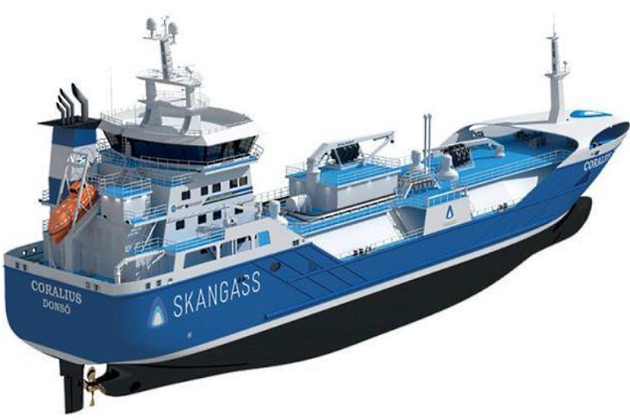
Fig. 8 LNG Bunkering vessel – SKANGASS Coralius
With a significantly higher capacity (of 5 800 m3) of LNG, higher bunkering transfer rates, and longer periods of LNG storage onboard, vapour management options are fundamental design features for such vessels.
Unless the LNG bunker vessel/barge tanks are designed to withstand the full gauge vapour pressure of the gas under conditions of the upper ambient design temperatures, means are to be provided to maintain the tank pressure below the MARVS by consuming or managing the natural LNG boil-off at all times, including while in port, manoeuvring or standing by.
Systems and arrangements that may be used for this purpose include one or a combination of the following methods:
- Pressure accumulation, whereby the LNG is allowed to warm up and increase the tank pressure. The tank insulation, design pressure or both are to be adequate to provide for a suitable margin for the operating time and agreed cargo loading temperatures involved.
- LNG vapour re-liquefaction system, through an onboard installation that allows the vessels to re-liquefy its own generated LNG vapour. It is here also possible to re-liquefy the return vapour from the receiving vessel, for re-liquefaction.
- Burning of natural or forced BOG in an approved consumer such as a Gas Combustion Unit, dual fuel diesel engine or other approved combustion unit.
- LNG fuel cargo cooling, with system to keep the LNG in the storage tanks down in cryogenic temperature, avoiding the excess in BOG.
It is assumed that maintenance (both planned and condition-based) is appropriate for the truck LNG bunkering equipment (including tank, piping, PRVs, LNG pump and monitoring equipment/sensors).
For more operational related aspects related to LNG vapour management (BOG management) reference is made to article https://sea-man.org/lng-bunkering-operation.html#bunkering-procedure.
Table 4, in the next page, includes some of the LNG bunker vessels/barges potential causes for operational related methane release. Technical and operational measures are presented for corresponding risk reduction.
| Table 4. LNG Bunker vessel/barge – Methane release mitigating measures | |||
|---|---|---|---|
| LNG Bunkering/LNG small Scale supply chain | Potential release scenario | Methane Release – Risk mitigating measures | |
| Technical | Operational | ||
| LNG bunker vessels/barges | If the tank is not in Cold condition (BOG temperature < 120 °C) filling with new LNG will generate excessive BOG. Release of LNG vapour may occur if MARVS is exceeded. PRV will open to relief pressure. | Provide technical means to cool-down with own LNG or Inert Gas/Nitrogen | Plan for LNG loading in cold condition (either LNG or Nitrogen) |
 | Cool-down with nitrogen plant or own LNG vapour. | Avoid waiting times in warmer tank temperatures. | |
| During LNG loading, at higher rates, if vapour pressure is not properly controlled there is the probability to exceed MARVS. Release of LNG vapour may occur if MARVS is exceeded. PRV will open to relief pressure. | Adequate monitor for LNG tank vapour pressure. | Top-bottom filling of LNG fuel cargo tank to allow cool-down of top vapour side of the tank. | |
| Communications and ESD high-pressure actuation for last resource. | |||
| If the bunker barge/vessel LNG fuel cargo tank already contains older (aged) LNG there is the possibility for stratification. Probability for “rollover” with peak excessive BOG generation. | Follow preventive technical measures for detection and prevention in SIGTTO Guidance: Guidance for the Prevention of Rollover in LNG Ships. | Definition of clear onboard procedures for corrective measures once stratification is detected. | |
| (LNG vessel/barge filling operation in small-scale LNG storage facility) | If the bunker barge/vessel LNG fuel cargo tank is loaded with LNG/nitrogen mixture there will be the possibility for auto- stratification to occur. Probability for “rollover” with peak excessive BOG generation. | Follow preventive operational measures for detection and prevention in SIGTTO Guidance: Guidance for the Prevention of Rollover in LNG Ship. | |
| LNG bunker vessels/barges | One, or a combination, of the following technical measures shall be considered to manage large columes of LNG vapour: | Ensure adequate pre-bunkering procedures to be followed by BFO and RSO. | |
 | During LNG bunkering transfer to receiving ship, especially for large bunkering volumes, at higher transfer rates, it is possible that large amount of BOG is generated. Possibility of methane release if LNG vapour return is such that vapour pressure in bunker vessel LNG tank exceeds MARVS. | Pressure accumulation. | Condition prior to bunkering to be carefully checked. |
| If the receiving ship tank is not in Cold condition (BOG temperature < 120 °C) filling with new LNG will represent high rate of vapour return. Release of LNG vapour may occur if MARVS is exceeded. PRV will open to relief pressure. | LNG vapour re-liquefaction system. | ||
| Burning of natural or forced BOG in an approved consumer such as a Gas Combustion Unit, dual fuel diesel engine or other approved combustion unit. | |||
| LNG fuel cargo cooling. | |||
| If the LNG bunkering line is excessively long (for instance, when the delivery and receiving flanges are far apart) excessive LNG vapour pressure may build-up inside the bunkering line. Vapour pressure generated in the bunkering line will return through LNG vapour return line. Excess of LNG vapour may take MARVS to be exceeded. PRV will open to relief pressure. | Minimize length of LNG bunkering lines. | Bunker vessel/barge delivery manifold station to be as close as possible side-by-side to LNG receiving vessel bunkering station. | |
| Use properly insulated hose whenever possible. | Minimization of trapped volume. | ||
| For rigid arms use vacuum insulated feeding and bunkering pipes where possible. | |||
| (LNG bunkering transfer operation) | If draining/purging/inerting procedure is not adequately performed there is the possibility that some LNG/NG will remain in the bunkering line. Release of LNG vapour may occur if bunkering hoses are disconnected with LNG/NG still in some point of the line. | Gas measurement to be performed before hose is disconnected. | Ensure draining is effective. |
| (bunkering with vapour return) | Avoid formation of “U” shapes where LNG can lay arrested. | Check for the existence of exterior ice cap (as an indicator for the presence of LNG inside the line) – heat up with water. | |
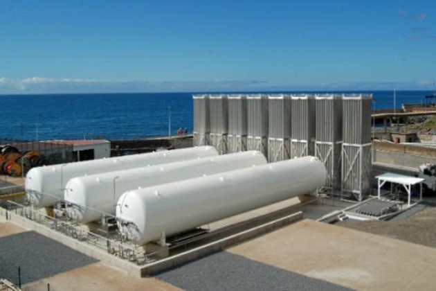
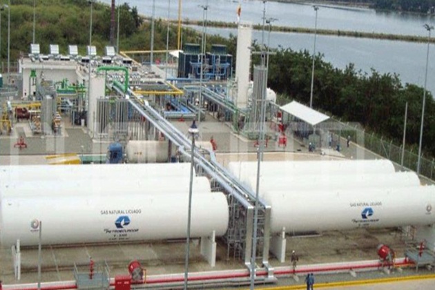
Small Scale Fixed LNG bunkering Stations
Fixed LNG bunkering stations are infrastructures, as presented in section LNG IMO Tanks/Containment Systems“LNG bunkering stations”, (figures 7 “Mechanical arm for hose handling” to 8 “Fixed LNG bunkering installations”) which can have very different levels of complexity, with some specific features that are outlined below:
- Very often, these installations are unmanned. In the few cases where they are manned, the personnel are reduced to the minimum and they are only on site for maintenance or unloading operations.
- Most of the small scale storage and re-liquefaction plants are built with prefabricated equipment (like in the industrial gases industry) and pre-assembled modules brought directly to site, providing a faster project schedule especially regarding the tank (which is usually the long lead item on a conventional terminal).
- In some cases, pressure build up is used in tanks prior to bunkering transfer instead of a pump.
- LNG inventory is lower, allowing in most cases scaled safety measures and simpler safety devices, without compromising on the overall plant safety level.
- Maintenance is reduced as there are very few rotating parts and instrumentation.
- Very often the LNG transfer is through a flexible hose, using a dry break coupling as the emergency disconnection system. Boil off gas generated naturally or due to LNG processing is handled in the pressurized tank, until it is condensed with the next subcooled delivered LNG or by utilization of backup liquid nitrogen.
- Small re-liquefaction units are part of the preferred equipment for their simplicity and the absence of operating expenditures.
For the purpose of methane release mitigation, more than aspects related to the operation, it is important to focus on BOG management as a key driver to mitigate the risk of methane emissions to the atmosphere.
For a detailed overview of the possible BOG management/mitigation strategies available for LNG fixed bunkering station, refer to article https://sea-man.org/lng-bunkering-operation.html#bunkering-procedure.
Again, as indicated in the previous sections, for trucks and barges/vessels, it is assumed that maintenance (both planned and condition-based) is appropriate for the fixed bunkering station LNG bunkering equipment (including tank, piping, PRVs, LNG pump and monitoring equipment/sensors).
LNG bunkering from small-scale LNG facilities or storage, such as the ones presented in figures 9 to 11, is typically done by loading on trucks or small LNG bunker vessels/barges, for off-site LNG bunkering location and, by pipeline via fixed manifold connection, for close bunkering transfer point.
Source: CRYONORM
With a different combination of pressure tanks than the one presented above, it is here also possible to appreciate how small scale LNG infrastructure can be modularized and limited in terms of area footprint.
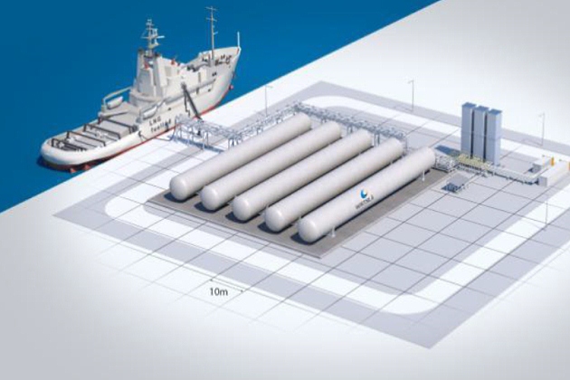
Source: WARTSILA
Sometimes a small jetty will be required if loading onto dedicated small LNG vessels is part of the business case.
LNG bunkering stations, as presented in summary in Section LNG IMO Tanks/Containment Systems“LNG bunkering stations”, are installations with a fair potential for modularization. Notwithstanding this the transfer systems require typically quite some space due to safety distances, which in some environments also requires significant civil work (jetty length, truck plot space). Other equipment items found in the transfer area are safety systems (i. e. gas and fire detectors, ESD panels and firefighting equipment), interface for the crew or truck driver (panels, control rooms), custody transfers (Coriolis or flow meters with gas chromatographs) and LNG spill containment. For truck units, small loading arms or hoses are quite common. Typically, 3″ is the largest hose diameter found for truck loading. For LNG bunker vessels/barges typically hoses are only used if the diameter is below 8″. For 4inch and larger also often loading arms are available.
It will be interesting: Development of Natural Gas Liquefaction Cycles based on Energy and Exergy Analyses
The transfer flow can be typically created by pressure build up when using pressurized storage, submerged pumps or external sealless cryogenic pumps. For cooling down the transfer lines and custody equipment before the transfer, a recycle line is required for recycling the initial BOG creation during cool down. In most LNG systems, a purging option (typically N2) to purge out the remaining amount of LNG after the transfer is also present. Alternatively, the lines can be continuously kept cold by LNG recycle flows. Transfer of LNG generates typically some BOG which needs to be handled. When there are BOG compressors, they need to be adequately sized to cope with the fluctuating BOG by LNG transfer.
As previously indicated for LNG bunkering mobile units (trucks, vessels/barges) the key focus for methane release mitigation from small scale fixed installation is still very much related to the handling of LNG vapour, not only as a result from ageing of LNG inside the storage tanks but also how purging, draining and inerting procedures are set up.
| Table 5. LNG Bunker Station – Fixed LNG bunkering onsite storage – Methane release mitigating measures | |||
|---|---|---|---|
| LNG Bunkering/LNG small Scale supply chain | Potential release scenario | Methane Release – Risk mitigating measures | |
| Technical | Operational | ||
| LNG small scale onsite storage | If the LNG storage tank already contains older (aged) LNG there is the possibility for stratification. Probability for “rollover” with peak excessive BOG generation. | Follow preventive technical measures for detection and prevention of statification in the relevant design codes. | Definition of clear procedures for corrective measures once stratification is detected. |
 | If the LNG storage tank is loaded with LNG/nitrogen mixture there will be the possibility for auto-stratification to occur. Probability for “rollover” with peak excessive BOG generation. | Follow preventive operational measures for detection and prevention in the relevant operational codes for avoidance of LNG statification in storage tanks. | |
| For Atmospheric Tanks, if LNG Vapour management does not respond to the necessary re-liquefaction rate (or condensing/refrigeration) excessive BOG will be generated. At atmospheric pressure there is no ability in the tank to sustain na increase in pressure. Release of LNG vapour will occur if pressure relief valve is actuated. | Storage tank to be designed. | for adequate holding time (time between loading and off-loading). | |
| Insulation, Re-liquefaction and refrigeration for adequate LNG vapour management. | |||
| For Pressure Tanks, if excess boil-off accumulates, leading to pressure increase in the storage tank (BOG can be here originated both from loading, off-loading or during holding period) There will be a certain (limited) ability of pressure tanks to sustain higher vapour pressures. Release of LNG vapour will occur if pressure relief valve is actuated. | Possible technical measures to mitigate BOG generation in pressurized LNG tanks: | Adequate control of LNG properties inside the storage tank. | |
| Insulation (vacuum insulation). | Procedure in place to avoid BOG release through PRV. | ||
| Top-spraying to coolddown/condense LNG vapour. | Plan for adequate LNG consumption, to avoid long holding times. | ||
| Refrigeration with internal coils. | |||
LNG ISO containers
LNG ISO containers have the potential to play an important role in the near future as they can provide flexibility to ships or ports adopting LNG as fuel through the implementation of modification and conversion projects allowing for modularity and the convenience of ISO standardized LNG fuel containers. These advantages and already some characteristics of this specific LNG fuel storage unit have already been presented in LNG IMO Tanks/Containment Systems“LNG bunkering stations”.
LNG ISO containers are typically LNG pressurized storage tanks contained within and ISO frame that allows the LNG to be transported through the wider logistical chain. Applications can be diverse but for the present case the analysis is strictly on the use of ISO LNG containers for LNG transfer from shore to the receiving ship (i. e. ISO containers that are embarked for plug-in, onboard LNG fuelled ships, are not covered as they are covered by the IGF Code).
Below, in table 6, some methane release mitigating measures are listed, which should be taken into account when using LNG ISO containerized pressure tanks for LNG bunkering.
| Table 6. LNG ISO container units – Methane release mitigating measures | |||
|---|---|---|---|
| LNG Bunkering/LNG small Scale supply chain | Potential release scenario | Methane Release – Risk mitigating measures | |
| Technical | Operational | ||
| LNG ISO container | If the tank is not in Cold condition (BOG temperature < 120 °C) filling with new LNG will generate excessive BOG. Release of LNG vapour may occur if MARVS is exceeded. PRV will open to relief pressure. | Provide technical means to cool-down with own LNG or Inert Gas/Nitrogen | Plan for LNG loading in cold condition (either LNG or Nitrogen) |
 | Cool-down with nitrogen vapour before filling. | Avoid waiting times in warmer tank temperatures. | |
| During LNG loading, at higher rates, if vapour pressure is not properly controlled there is the probability to exceed MARVS. Release of LNG vapour may occur if MARVS is exceeded. PRV will open to relief pressure. | Adequate monitor for LNG tank vapour pressure. | Top-bottom filling of LNG fuel ISO tank to allow cool-down of top vapour side of the tank. | |
| LNG ISO container | If the ISO LNG tanks are kept full, waiting, for longer than the specified holding time, excess LNG vapour will be generated. Release of LNG vapour may occur if MARVS is exceeded. PRV will open to relief pressure. | Possible technical measures to mitigate BOG generation in pressurized LNG tanks: | Adequate control of LNG properties inside the storage tank. |
 | Insulation (vacuum insulation). | Procedure in place to avoid BOG release through PRV | |
| Top-spraying to coolddown/condense LNG vapour | Plan to avoid waiting times longer than the holding time reference for the LNG ISO container. | ||
| (Holding Mode) | Refrigeration with internal coils. | ||
| LNG ISO container | During LNG bunkering, if receiving tank is warmer there will be excessive BOG generation. Release of LNG vapour may occur if MARVS is exceeded. PRV will open to relief pressure. | Proper tank equalization needs to be ensured prior to LNG fuel transfer. | Ensure adequate pre-bunkering procedures to be followed by BFO and RSO. |
 | Cool-down of receiving tank and bunkering lines needs to be ensured with the minimum LNG vapour possible. | Condition prior to bunkering to be carefully checked. | |
| or bunkering transfer LNG trucks can use pressure-buil-up units to transfer LNG to RSO by increase in Vapour pressure on top of the tank. If MARVS pressure is exceeded during pressure build-up | LNG pressure monitor | Adequate operating procedure for LNG transfer by pressure build-up. | |
| LNG regulator before pressure build-up unit. | |||
| Malfunction and alarm conditions will lead to ESD actuation in RSO. If ESD not fully compatibe with LNG ISO tank system there is the risk that following the RSO bunkering valve is shut pressure will build-up in the bunkering line (and in the truck LNG tank). Release of LNG vapour may occur if MARVS is exceeded. PRV will open to relief pressure. | Fully compatible ESD to be used between LNG ISO tank. | Adequate procedures to be in place to avoid excessive BOG generation and methane release, following bunkering stop. | |
| Adequate pressure monitoring to ensure no excess BOG is generated in the LNG truck tank after bunkering has been ESD-stopped. | |||
| Include back-pressure regulator into the circuit (regulated above operating pressure and below MARVS). | |||
Intermittent flow applications
There are cases where LNG is provided directly from an LNG truck trailer or ISO LNG containerized pressure tank directly into the LNG fuelled ship. This operation, considered as bunkering within the scope of the present Guidance, is a very particular application where different factors need to be taken into account.
One particular factor that is relevant for LNG vapour management control, and methane release mitigation, is the possible intermittency in supply flow rate.
In the cases where LNG is delivered for intermittent flow applications, or where brief interruptions in the vaporization process, an accumulator tank should be considered in the vaporization system with a safe but higher than operating pressure relief valve.
In the particular case of figure 12, an LNG fuelling operation is shown where an LNG ISO container (wheeled) is used to provide LNG fuel to harbour DF generator onboard an LNG fuelled ship (AIDA Prima).
Source: AIDA
Constant flow into vaporizer (onboard) may be achieved if generator works at near-constant load, with negligible load variation.
LNG Pipelines
LNG pipelines are typically not very long. Some references indicate 250 m as a reference maximum distance and, even if we consider longer distances, this is taken for the purpose of the present Guidance as an indicative figure. The length of LNG pipeline systems is mostly limited by insulation limitations and the need to limit the inevitable heat exchange along the length of the pipeline. This is the case even if highly advance insulating material or vacuum jacketing insulation are used.
Read also: Liquefied Natural Gas Projects, calculation of the cost of gas production
For the purpose of identifying potential for methane release scenarios LNG pipelines are elements where fugitive losses are not to be expected. On one hand they would be highly insulated (in principle double-walled) and no bolted flanges should be expected as the different sections of the pipeline will be welded together.
LNG pipelines will typically be installed in fixed LNG bunkering stations, possibly connecting LNG pressure storage tanks to LNG bunkering rigid arms.
A Pipeline Integrity Management System (PIMS) adequate for the LNG pipeline installation/ infrastructure should be in place, providing not only the identification of all the technical elements in the pipeline but also identifying all objectives in place to ensure adequate Pipelines in Marine Terminals: Key Considerations for Handling Liquefied Gaspipeline safety and integrity.
Environmental objectives, in particular, shall give expression to zero-methane release to the atmosphere.
Good Environmental Practice for LNG Bunkering
General
Environmental benefits of LNG as fuel should be potentiated and highlighted in the context of adequate policy measures designed for local air quality improvement. Here PAAs can play an important role in facilitating the adoption of measures that highlight the environmental potential of LNG as an Alternative Fuel for shipping, whilst establishing clear limitations on potential operational NG emissions.
The impact of including LNG as fuel development into a given port service portfolio should be highlighted in the context of its wider contribute to Sustainability and to the development of an increasingly cleaner energy source for maritime, inland and road transport. As multi-modal hubs, ports can in fact play an important role in highlighting the potential of LNG in a Port-centric small scale LNG development.
LNG as fuel, however, only represents an environmental sustainable option, as an alternative fuel, if methane’s GHG potential is adequately addressed. PAAs should have provisions in place prohibiting any type of methane release to the atmosphere, with the only exception of emergency situations.
No methane release to the atmosphere shall result from LNG bunkering operations, considering all infrastructure elements, mobile units involved or operational procedures implemented. PAAs should ensure that adequate environmental practice is promoted in all aspects related to LNG storage, distribution, on-site transfer and bunkering.
Methane Release Mitigation
PAAs should require Operators to demonstrate that an adequate set of measures to mitigate the release of natural gas to the atmosphere are in place, adequately identified in LNG Bunkering Plan.
The avoidance of methane release to the atmosphere should be expressed by the BFO as an objective in a relevant Quality Management System. Management systems that can be used are ISO 9001, ISO 14001, ISM, ISO/TS 29001 and API Spec Q1 (as specified in EN ISO 20519).
Methane release mitigation measures should be:
a. Relevant (the measures listed by the BFO should relate to the actual LNG bunkering process in place. They should be directly related and adapted to the different stages in the LNG bunkering process).
b. Enforceable (PAAs should be able to confirm actual practice of the measures presented for methane release mitigation. Not only it should be possible to confirm the actual implementation of the technical but also the operational measures in place).
c. Safe (from the implementation of the presented methane release mitigation measures no potential unsafe operation or condition should derive).
d. Quantifiable (it should be possible to quantify, through the adoption of the listed methane mitigation measures, the amount of methane that is not sent to the atmosphere).
Different LNG bunkering and small scale LNG projects will have very different characteristics, with different bunkering modes, arrival of LNG to the port and, potentially, even storage on-site. Different technical characteristics, LNG capacities and bunkering rates will represent also different methane release mitigating measures, adequate and applicable to different LNG bunkering solutions.
PAAs should ensure that the BFO presents a combination of the methane release mitigation measures summarized into 4 (four) distinct groups (including in all cases both technical and operational measures):
| Four groups of combinations of measures to reduce young methane | ||
|---|---|---|
| a) Boil Off Gas (BOG) management | i. Minimization of trapped volume inventory; | |
| ii. Loading, off-loading and bunker transfer operations with similar tank temperatures, at BFO and RSO sides; | ||
| iii. LNG transfer rates to be adjusted to the ability from both BFO and RSO to handle BOG; | ||
| iv. Holding times in pressurized LNG storage tanks not to be exceeded, unless adequate BOG management in place. | ||
| v. Vapour return: | (1). For bunkering of ships with atmospheric LNG tanks (IMO type A, B or Membrane) a vapour return line should always be provided. | |
| (2). For bunkering of ships with pressurized LNG tanks (IMO type C) a vapour return line may be provided. It is a possibility that the receiving ship is able to cope with some pressure increase due to LNG vapour generation. | ||
| vi. Vapour management – On either side (RSO or BFO) the following options can be considered for LNG vapour management purposes: | (1). Pressure accumulation (if pressure tanks are considered). | |
| (2). Re-liquefaction. | ||
| (3). Refrigeration. | ||
| (4). Gas consumption (GCU or onboard gas consumers). | ||
| b) Maintenance | i. Maintenance of all equipment involved in LNG bunkering should follow programmed maintenance program as per manufacturer indication. | |
| ii. Operators must hold, for each piece of separate LNG bunkering equipment: | (1). Valid Certificate | |
| (2). Maintenance record | ||
| c) Planning | i. Plan transport, storage and bunkering according to expected demand, accounting for the specific holding times of storage elements and infrastructure in place. | |
| ii. Avoid waiting times in holding mode | ||
| iii. Develop a plan, involving an agreement between BFO and RSO for implementation of an adequate LNG bunkering sequence, where the whole streamlined process is well understood and shared. | ||
| d) Compatibility | i. A compatibility assessment of the bunkering facility and receiving ship should be undertaken prior to confirming the bunkering operation to identify any aspects that require particular management. | |
| ii. As a minimum, compatibility assessment should be undertaken for the systems and equipment listed in IACS Recommendation 142, LNG Bunkering Guidelines. | ||
| e) Purging and Inerting | i. Purging and Inerting procedures should be part of the LNG Bunkering Management Plan, to be presented by the BFO, allowing PAAs to understand the full technical and operational details supporting the procedures (bunkering transfer hose(s) and vapour return). | |
| ii. Any mixture of inert gas (e. g. nitrogen) and natural gas should be recovered, either by the BFO or RSO, and not vented. | ||
Venting to the atmosphere, either resulting from automated or manual action, through PRV actuation, or through any other possible outlet from the LNG storage or bunkering system, should be only possible in case of emergency, for safety reasons.
An emergency venting of LNG vapours should be reported, quantified and the reasons, leading to the emergency venting to occur, understood and subject to analysis.
It will be interesting: General information and Rules for Ships carrying LNG and LPG
Notwithstanding the possibility of venting in case of emergency it should not suffice to justify this with a vapour pressure increase. Bunkering and containment systems for LNG fuel on either side of the bunkering interface should be designed for the intended operations and there should be limitations in physical/operation parameters (flow rates and temperatures).
PAAs should develop a reporting mechanism for emergency venting that promotes a diligent and voluntary action from operators.
In addition to abive, for a higher level of enforcement, PAAs can consider the possibility of requiring the installation of methane detectors (also known as natural gas detectors) equipped with tamper-proof recording, in a suitable location of the venting mast.
Environmental Management Systems
As a best practice provision PAAs should require Operators to have Environmental Management Systems in place, certified according to a recognized EMS such as ISO 14001:2015, certified by an independent certification body.
An EMS would allow:
- An holistic approach to environmental impacts, where methane release throughout the entire LNG bunkering could be addressed (and not only venting events).
- Focusing on only critical aspects and processes.
- Making use of time-tested, mature approaches recognized worldwide.
- Establishment of a positive relationship between PAAs and Operators.
The purpose of the EMS should be to implement general requirements and guidelines that, when followed, should provide reasonable assurance that the outputs from the LNG bunkering operation will have minimal negative environmental impact and improved environmental performance. It should, in this regard, be noted that the ISO 14001 standard is nonprescriptive; that is, it details what should be done, not necessarily how to do it.
The EMS in place should be based on a “plan-do-check-act” (PDCA) model of improvement, an iterative process that must be applied regularly to ensure benefits are being realized and the standard is being upheld. The primary operational components of an EMS can be grouped as follows:
a. Create/update environmental company policy
Operators’ environmental company policies should allow PAAs to ascertain the level of the commitment with the particular aspect of methane emissions.
b. Plan:
- Environmental aspects;
- Legal and other requirements;
- Objectives, targets, and programs.
d. Do:
- Resources, responsibilities, and authority;
- Competence, training, and awareness;
- Communication;
- Documentation;
- Control of documents;
- Operational control.
d. Check:
- Monitor and measure;
- Evaluate compliance;
- Nonconformity, corrective and preventive action;
- Control of records;
- Internal audits.
e. Act:
- Management review;
- Audit.
Should the PAA also have any type of EMS certification, LNG bunkering as a service has the potential to contribute directly to any possible local air quality objectives. This is directly the consequence of LNG being a much cleaner fossil fuel when compared to oil fuels. It is nevertheless important to express objectives into the EMS regarding GHG emissions mitigation.
Any potential GHG emissions objectives and measures should be clearly expressed into PAAs EMS system.

- Study on the completion of an EU framework on LNG-fuelled ships and its relevant fuel provision infrastructure, LOT 1 Position paper: Towards harmonized EU LNG bunkering guidelines, DNV-GL, 2016.
- Study on the completion of an EU framework on LNG-fuelled ships and its relevant fuel provision infrastructure, LOT 1 Final Report, DNV-GL, 2016.
- LNG Bunkering Guidelines IACS Recommendation n. 142, on LNG Bunkering, IACS, 2016.
- ISO/TS 18683:2015. (15-Jan. 2015). Guidelines for systems and installations for supply of LNG as fuel to ships. Technical Specification.
- Society for Gas as a Marine Fuel (SGMF). (2015). Gas as a marine fuel, safety guidelines, Bunkering. Version 1.0, February 2015.
- ISO 20519:2017. Ships and marine technology – Specification for bunkering of gas fuelled ships. (International Standard).
- IEC 60079-10-1. (2015). Explosive atmospheres – Part 10-1: Classification of areas – Explosive gas atmospheres.
- Directive 1999/92/EC – ATEX of the European Parliament and of the Council of 16 December 1999 on minimum requirements for improving the safety and health protection of workers potentially at risk from explosive atmospheres (15th individual Directive within the meaning of Article 16(1) of Directive 89/391/EEC).
- API RP-500. 1997. Recommended practice for classification of locations for electrical installations at petroleum facilities classified as CIass 1, Division 1 and Division 2. Washington. D.C: API.
- API RP-505. 1997, Recommended practice for classification of locations at petroleum facilities classified as Class I, Zone 0, Zone 1 and Zone 2. Washington, D.C. API.
- NFPA 497. 2012, Recommended practice for the classification of flammable liquids, gases or vapours and of hazardous (classified) locations for electrical installations in chemical process areas. Quincy, MA: NFPA.
- IEC EN 60079-10-1 Ed.1.0, 2008. Electrical apparatus for explosive gas atmospheres – Part 10-1: Classification of areas – Explosive gas atmospheres. International Electrotechnical Commission.
- Commission Decision 2010/769/EU of 13 December 2010 on the establishment of criteria for the use by liquefied natural gas carriers of technological methods as an alternative to using low sulphur marine fuels meeting the requirements of Article 4b of Council Directive 1999/32/EC relating to a reduction in the sulphur content of certain liquid fuels as amended by Directive 2005/33/EC of the European Parliament and of the Council on the sulphur content of marine fuels (OJ L 328, 14.12.2010, p. 15).
- USCG CG-OES Policy Letter 02-14 – Guidance Related To Vessels And Waterfront Facilities Conducting Liquefied Natural Gas (LNG) Marine Fuel Transfer (Bunkering) Operations.
- ADN – European Agreement concerning the International Carriage of Dangerous Goods by Inland waterways (Update version ADN January 2017).
- ADR – European agreement concerning the International Carriage of Dangerous Goods by Road (Update version ADR January 2017).
- Rhine Vessel Inspection Regulations (RVIR).
- EU general risk assessment methodology (Action 5 of Multi-Annual Action Plan for the surveillance of products in the EU (COM(2013)76) – Document 2015-IMP-MSG-15 – 16 October 2015.
- Safety Study, Chain analysis: Supplying Flemish ports with LNG as a marine fuel, Analysis of safety aspects, June 2012.
- EN 1160 – Installations And Equipment For Liquefied Natural Gas – General Characteristics Of Liquefied Natural Gas, NBN, 1st edition, August 1996.
- ESD Arrangements & Linked Ship/Shore Systems for Liquefied Gas Carriers, SIGTTO First Edition 2009 – SIGTTO.
- M. Kofod & S. Hartman, T. Mundt – Review of Recent Well-to-Wake Greenhouse Gas Studies evaluating the use of LNG as a marine Fuel, IMO MEPC/INF.15.
- LNG Access Code for Truck Loading for The Zeebrugge LNG Terminal – Based on version approved by the CREG on September 19th 2013 – Applicable as of January 1st 2014 – FLUXYS.
- Guidance for the Prevention of Rollover in LNG Ships – SIGTTO – First Edition 2012.
- Wang, Siyuan & Notteboom, Theo – The role of port authorities in the development of LNG bunkering facilities in North European ports, 14 January 2015, World Maritime University 2015.
- Verhoeven P (2010) A review of port authority functions: towards a renaissance? Marit Policy Manag 37:247-270.
- Society for Gas as a Marine Fuel (SGMF). (2017). Gas as a marine fuel, safety guidelines, Bunkering. Version 2.0, February 2015.
- COM(2003) 515 final – Communication from The Commission concerning the non-binding guide of good practice for implementing Directive 1999/92/EC of the European Parliament and of the Council on minimum requirements for improving the safety and health protection of workers potentially at risk from explosive atmospheres, Brussels, 25.8.2003.
- Davies, P. (2016) – Bunkering LNG: Setting the Safety Zone, 7th Motorship Gas Fuelled Ships Conference, November 2016.
- International Association of Oil & Gas Producers. (1-Mar 2010). Risk Assessment Data Directory – Process Release Frequencies. Report No. 434 – 1, 1 March 2010). Pertinent data from this report is summarised in: Davies & Fort, (Sept 2012), LNG as Marine Fuel – Likelihood of LNG Releases, Journal of Marine Engineering and Technology.
- PGS2 – TNO Yellow Book – Methods for the calculation of physical effects, due to releases of hazardous materials (liquids and gases) – CPR 14E (3rd Edition, 2005) – TNO – The Netherlands Organization of Applied Scientific Research.
- OECD Guiding Principles for Chemical Accident Prevention, Preparedness and Response, Guidance for Industry (including Management and Labour), Public Authorities, Communities, and other Stakeholders – 2nd Edition (2003) – OECD Environment, Health and Safety Publications.
- DNVGL-RP-G105 Edition October 2015 – Development and operation of liquefied natural gas bunkering facilities, Recommended Practice, DNV GL, 2015.
- USCG CG-OES Policy Letter No. 01-17 – Guidance for Evaluating Simultaneous Operations (SIMOPS) during Liquefied Natural Gas (LNG) Fuel Transfer Operations.
- LGC NCOE Field Notice 01-2017 – 14-Aug-17 – Recommended Process For Analysing Risk Of Simultaneous Operations (SIMOPS) During Liquefied Natural Gas (LNG) Bunkering.
- An Overview of Leading Software Tools for QRA, American Society of Safety Engineers – Middle East Chapter (161), 7th Professional Development Conference & Exhibition, March 18-22, 2005.
- Walter Chukwunonso Ikealumba and Hongwei Wu (2016) Some Recent Advances in Liquefied Natural Gas (LNG) Production, Spill, Dispersion, and Safety School of Chemical and Petroleum Engineering, Curtin University.