LNG Risk Management is essential for ensuring the safe and efficient use of liquefied natural gas as a marine fuel. This article explores critical components such as risk assessments, hazards, and safeguards, alongside detailed studies like siting studies and fire risk assessments.
- Risk Assessment
- Hazards
- Risks
- Safeguards
- Siting Study
- Simultaneous Operations
- Fire Risk Assessment
- Waterway Suitability Assessment
- Process Hazards Analyses
- Sources of LNG and Project Implementation to Make LNG Available for Use as a Marine Fuel
- Potential LNG Supply Sources
- APPENDIX C – Summary of Regional Bunkering Infrastructure
- LNG Import Facilities
- LNG Fuel Distribution Facilities for Other Transportation Modes
- Examples of Proposed Bunkering Facilities
- Example of LNG Offerings to the Marine Industry Using Existing LNG Facilities
- AGL Resources
- GDF Suez advance LNG Project
- Securing LNG Supply for Bunkering
It also examines potential LNG supply sources, import facilities, and distribution networks, highlighting examples of proposed bunkering facilities and existing offerings in the marine industry, including notable projects like AGL Resources and the GDF Suez Advance LNG Project. By addressing these elements, the article aims to provide valuable insights into securing LNG supply for bunkering operations.
Risk Assessment
In addition to the regulatory requirements identified in LNG Bunkering Guidelines: Comprehensive Insights and Best Practices for Operators“Guidelines for Gas-fueled Vessel Operators”, LNG Bunkering Guidelines: Comprehensive Insights and Best Practices for Operators“Guidelines for Bunker Vessel Operators” and LNG Bunkering Guidelines: Comprehensive Insights and Best Practices for Operators“Guidelines for Bunkering Facility Operators”, a number of the elements identified are considered specific studies. LNG Bunkering Guidelines: Comprehensive Insights and Best Practices for Operators“Key Elements of Applicable Regulations, Codes, Standards & Guidelines for Bunker” identifies which regulations require the specific studies, and the following sections provide more details about each. Whether any of these types of studies are needed and when they should be performed should be defined in early planning by a bunkering project and the applicable regulators.
In general, a bunkering facility should plan on providing a risk assessment that addresses bunkering activities to help define the risk reduction measures that should be considered. The risk assessment characterizes the losses that may occur during the operation of the LNG bunkering terminal. Risk assessment methods may be qualitative or quantitative and should follow recognized standards, such as ISO 31010: Risk management – Risk assessment techniques or ISO 16901: Guidance on performing risk assessment in the design of onshore LNG installations including the ship/shore interface. The scope of the risk assessment may be tightly defined or broad enough to meet the risk assessment requirements of other studies listed in this section, including:
- siting study,
- Fire Risk Assessment (FRA),
- Waterway Suitability Assessment (WSA),
- and security assessment.
The risk assessment should address the following elements:
- Identification of potential hazards.
- Assessment of the likelihood that the hazard will occur.
- Assessment of the potential consequences; depending on the concerns of the owner/operator, the consequence assessment could consider a variety of impact types, including:
- impacts to people (both on site and off site),
- impacts to the environment,
- property damage,
- business interruption,
- and reputation.
- Identification of risk reduction measures if risk for hazard is not considered acceptable.
This study contains a general risk assessment in Appendix A for LNG bunkering alternatives using the HAZID method.
Hazards
Natural gas, primarily composed of methane (CH4), is a nontoxic flammable gas. LNG is created by cooling natural gas to a temperature below its boiling point of about -162 °C (-260 °F). This liquefaction process reduces the volume of the gas by a factor of 600, making it a much more efficient state for storage and transport. LNG is a cryogenic liquid that, if released from its storage or transfer equipment, presents unique hazards to nearby people and property when compared with traditional fuel oil. The primary hazards are:
Serious injuries to personnel in the immediate area if they come in contact with cryogenic liquids. Skin contact with LNG results in effects similar to thermal burns and with exposure to sensitive areas, such as eyes, tissue can be damaged on contact. Prolonged contact with skin can result in frostbite and prolonged breathing of very cold air can damage lung tissue.
Brittle fracture damage to steel structures exposed to cryogenic temperatures. If LNG comes into contact with normal shipbuilding steels, the extremely cold temperature makes the steel brittle, potentially resulting in cracking of deck surfaces or affecting other metal equipment.
Formation of a flammable vapor cloud. As a liquid, LNG will neither burn nor explode; however, if released from bunkering equipment, it will form a vapor cloud as the LNG boils at ambient temperatures. To result in a fire or explosion, the vapor cloud must be in the flammable range, which for methane is between 5,3 % and 14 % by volume in air, and there must be an ignition source present. There are a number of factors affecting the consequence potential of an LNG release, including:
- the surface it is released on,
- the amount released,
- air temperature,
- surface temperature,
- wind speed,
- wind direction,
- atmospheric stability,
- proximity to offsite populations,
- and location of ignition sources.
Although LNG vapors can explode (i. e., create large overpressures) if ignited within a confined space, such as a building or ship, there is no evidence suggesting that LNG is explosive when ignited in unconfined open areas.
Asphyxiation. If the concentration of methane is high enough in the air, there is a potential for asphyxiation hazard for personnel in the immediate area, particularly if the release occurs in confined spaces.
Risks
LNG’s hazards are different (e. g., volatility, cryogenic conditions) from traditional fuel oil and potential operators must clearly understand the risks involved with LNG bunkering. While each of the three Risk Assessment in the Liquefied Natural Gas Bunkering Operations, Hazard Identificationbunkering operations is unique, there are a number of common initiating events that can result in a release of LNG posing hazards to nearby people, equipment, and the environment. Table 1 presents the four initiating events that are risk drivers for LNG bunkering operations and identifies common causes for each event. Appendix A introduces a risk assessment process and provides risk assessment worksheet templates that could be applied to assess the risk of specific bunkering operations.
| Table 1. LNG Bunkering Initiating Events and Causes | |
|---|---|
| Initiating Events | Common Causes |
| Leaks from LNG pumps, pipes, hoses or tanks
| Corrosion/erosion |
| Fatigue failure | |
| Hose failure | |
| Improper maintenance | |
| Piping not cooled down prior to transfer | |
| Seal failure | |
| Use of inappropriate hoses (e. g., not LNG rated) | |
| Vibration | |
| Improper installation or handling | |
| Improper bunkering procedures | |
| Inadvertent disconnection of hoses
| Improper hose connection |
| Hose failure | |
| Excessive movement of the loading arm or transfer system | |
| Inadequate mooring or mooring line failure | |
| Supply truck drives or rolls away with hose still connected | |
| Supply vessel drifts or sails away with hose still connected | |
| Extreme weather (wind, sea state) | |
| Natural disaster (e. g., earthquake) | |
| Overfilling/overpressuring vessel fuel tanks
| Operator and level controller fail to stop flow when tank is full |
| External impact
| Cargo or stores dropped on bunkering equipment (piping, hoses, tanks) |
| Another vessel collides with the receiving vessel or bunkering vessel | |
| Vehicle collides with bunkering equipment | |


Safeguards
Historically, carriage and the transfer of maritime LNG have an outstanding safety record, and the safeguards associated with LNG import/export terminals are proven. While LNG bunkering involves far lower quantities and transfer rates when compared to import/exports, many of the safeguards apply to help ensure safety (Figure 1).
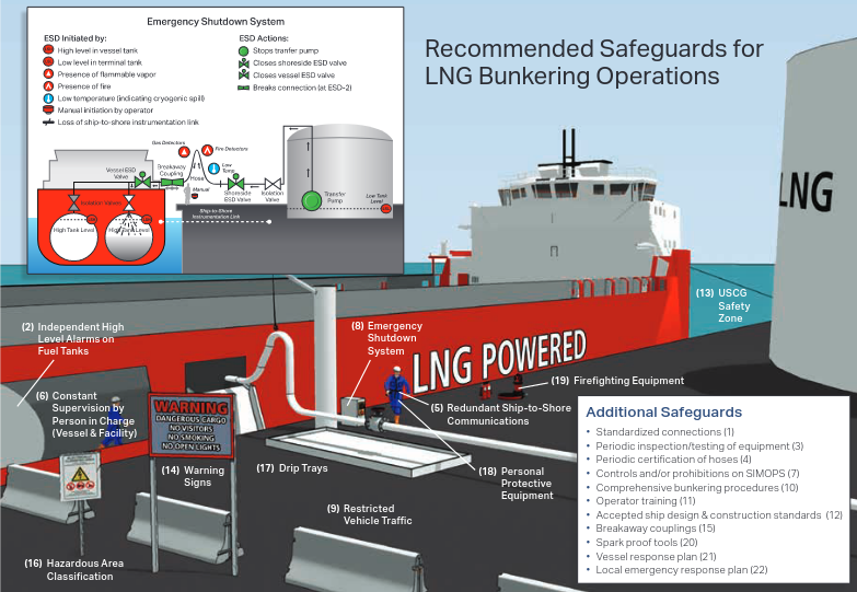
The collection of safeguards, which were developed based on a thorough evaluation of LNG-related regulations, codes, and standards, including the:
- International Association of Oil;
- and Gas Producers (OGP);
- and ISO’s Waterfront Facilities Handling LNG;
- and Liquefied Hazardous Gas;
- NFPA’s 59A – Standard for the Production;
- Storage;
- and Handling of LNG;
- and USCG’s CFR33 127 – Waterfront Facilities Handling LNG;
- and Liquefied Hazardous Gas;
are illustrated in Figure 1.
| Table 2. Prevention Safeguards | |
|---|---|
| Prevention Safeguards | |
| 1 | Standardized connections at bunkering station to prevent inadvertent leaks or hose disconnects. |
| 2 | Independent high level alarms on vessel fuel tanks to alert operators prior to tank overfill. Note: Separate high level switch initiates emergency shutdown (ESD) (See safeguard # 8) |
| 3 | Periodic inspection and testing of equipment prior to bunkering to ensure system is functional and there are no leaks |
| 4 | Periodic testing and certification of hoses to ensure hoses and fittings will not leak or disconnect during transfer |
| 5 | Ship-to-shore communications to ensure information can be shared between parties involved in bunkering (e. g., person in charge [PIC], ship crew, truck driver). |
| 6 | Constant supervision by PICs on both vessel and facility |
Collectively, they are designed to prevent accidental releases of LNG and mitigate the consequences if releases do occur. Each safeguard plays a unique role. Some are designed to prevent certain initiating events from occurring, others are designed to mitigate certain types of consequences, and some play a role in both prevention and mitigation.
| Table 3. Safeguards that Prevent and Mitigate | |
|---|---|
| Prevention Safeguards | Mitigation Characteristics |
| Controls and/or restrictions on SIMOPS | |
| Reduces likelihood of dropping cargo or stores on LNG transfer equipment or external impact from vehicles or equipment involved in simultaneous operations. | Reduces crew/passenger population in hazardous areas and reduces potential ignition sources from simultaneous operations. |
| ESD system | |
| Reduces likelihood of overfilling vessel fuel tanks through automatic shutdown on high level. | Reduces the amount of LNG release by closing valves and stopping transfer pumps during hazardous conditions. |
| Restricted vehicle traffic | |
| Reduces likelihood of vehicle impact with bunkering equipment. | Reduces population in hazardous area near vessel and limits possible ignition sources in the case of an LNG release. |
| Comprehensive bunkering procedures | |
| Addresses a broad array of prevention topics including: operating conditions, required equipment, safety, training, communications, mooring, connection, transfer, lifting, and disconnection. | Addresses a broad array of mitigation topics, including: safety, simultaneous operations, and emergency operations. |
| Operator training | |
| Covers a broad array of prevention topics to ensure that operators are trained in safe work practices and understand all tasks for normal and non-routine operations. | Covers a broad array of mitigation topics to ensure that operators are aware of LNG hazards and are trained for emergency operations. |
| Accepted ship design and construction standards | |
| Safe ship arrangements, manufacture, workmanship, and testing to minimize probability of LNG leaks. | Ship design standards to mitigate impactson people and property in case of an LNG release (e. g., fire safety equipment, electrical classification, ventilation). |
| Regulated Navigation Areas | |
| Reduces likelihood of vessel impact with bunkering equipment. | Reduces population in hazardous area near vessel and limits possible ignition sources in the case of an LNG release. |
| Warning signs | |
| Reduces likelihood of external impact with bunkering equipment. | Reduces population in hazardous area near vessel and limits ignition sources near bunkering operations to reduce likelihood of a fire if a release of LNG occurs. |
Table 2, Table 3, and Table 4 introduce each of the safeguards and describe their role in reducing risk of LNG bunkering operations.
| Table 4. Mitigation Safeguards | |
|---|---|
| Mitigation Safeguards | |
| Breakaway couplings on hose connections designed to minimize LNG releases in the case of excessive movement (e. g., truck drive-away, vessel drifting away). | |
| Hazardous area classification near bunkering operations where accidental releases could occur to limit ignition sources. | |
| Drip trays (aluminum or stainless steel) to collect and isolate LNG spills protecting ship areas from cryogenic hazards | |
| Personal protective equipment to protect operators from exposure to cryogenic and fire hazards | |
| Firefighting equipment, including dry chemical and water deluge systems, to mitigate fire damage if LNG release ignites. | |
| Spark-proof tools to reduce likelihood of ignition if LNG is released. | |
| Vessel emergency response plans with procedures to guide crew in addressing various LNG-related hazards | |
| Local emergency response plans with procedures to guide first responders in addressing various LNG– related hazards. |
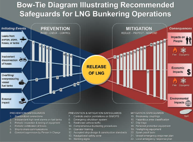
Using a bow-tie model, Figure 2 illustrates how the safeguards listed in the previous tables provide multiple layers of defense that both reduce the likelihood that each initiating event will result in an LNG release and mitigate the impacts on people, property, and the environment.
Siting Study
The determinations of where to locate an LNG facility whether it is storage only or includes liquefaction are quite complex and will likely have a major impact on the ultimate cost of the project. Factors to consider include:
- adequate land area;
- suitable land for construction;
- suitable marine access;
- potential environmental show stoppers;
- compatibility of adjacent facilities;
- and access to gas supply.
NFPA 59A 5.2.1 requires a written site evaluation be available to the:
- authorities;
- addressing potential incidents and mitigating measures;
- adjacent activities;
- severe weather patterns;
- other natural hazards;
- and security factors.
Potential Incidents and Minimum Land Area
LNG bunkering facilities store smaller volumes and generally require smaller land area as a buffer than LNG import and export facilities. In the US, the only codified siting criteria are NFPA 59A (LNG Bunkering Guidelines: Comprehensive Insights and Best Practices for Operators“Guidelines for Bunkering Facility Operators”) and DOT regulation 49 CFR 193 (Subpart B), which are used for those types of large LNG facilities. The objective for US standards is to ensure that an LNG facility controls a land area which might be affected by the consequences of a design spill. The consequences are the theoretical vapor dispersion distance of the unignited vapor or radiant heat from a fire if the vapor were ignited. The European standards use risk based criteria. European LNG import/export terminal risk criteria are located in EN-1473 for use where local risk standards do not exist. Criteria for small satellite plants, with storage capacities less than 200 tonne, are in EN-13645. NFPA 59A (2013) contains new performance based criteria (risk assessment Chapter 15) as an alternative to the LNG Bunkering Guidelines: Comprehensive Insights and Best Practices for Operators“Guidelines for Bunkering Facility Operators” method for demonstrating adequate land area, bringing US and European LNG marine facilities standards closer philosophically, though US regulatory experience has been almost exclusively with the deterministic approach.
The site evaluation should demonstrate compliance with vapor dispersion and thermal radiation threshold requirements or provide quantification of vapor dispersion and thermal risks to populations outside the LNG terminal to ensure they do not exceed acceptable levels. If the project follows the Qualitative or Quantitative Risk Assessment (QRA) approach, the release scenarios for risk evaluation shall be developed through the use of Process Hazard Analyses (PHA), Hazard and Operability [HAZOP], or other systematic HazID studies (NFPA 59A 15.5.1). A spectrum of release behaviors including:
- flashing;
- aerosol formation;
- jet fires;
- pool formation and flow;
- flash fire;
- explosions;
- and LNG with water interactions must be evaluated.
Severe Weather
Emergency response personnel should be able to access the site during any weather condition for personnel safety and fire protection. The site elevation should be above the flood plain and allow for adequate storm water drainage.
Other Natural Hazards
LNG storage facilities should be designed to withstand seismic activity according to local building code criteria. Shop-built containers should comply with the ASME Boiler and Pressure Vessel Code and seismic accelerations given in NFPA 59A (2013) Section 13.3.14. Where tsunami risks are credible, the storage tank elevation may need to be raised.
Compatibility with Adjacent Activities
Types of products and operations on adjacent berths, including different safety philosophies and requirements should be considered. Unacceptable risks from the bunkering activity and storage should not be imposed on adjacent facilities. Residential development, sensitive development (schools, hospitals, retirement homes, or sports stadiums), transportation infrastructure, retail and leisure development, and buildings for incarceration should not be affected by unacceptable risks.
Security
A security assessment covering hazards, threats, vulnerabilities and consequences to the facility is required by NFPA 59A 12.9.1. The assessment should be available to the authority having jurisdiction, but not publicly. Major facility components such as storage tanks, control buildings, process equipment, and transfer facilities should be enclosed by a peripheral fence or natural barrier and lit at night.
Marine Topography
The waterfront facility must have adequate water depth alongside for the range of vessels which will be loaded. Allowance for tide, trim and underkeel clearance should be considered. Dredging may be required to facilitate access. Access during all states of tide is preferable, but if not practicable, then removal from the berth to a safe anchorage shall be provided. If dredging is required, beneficial use of the spoil and environmental implications should be considered. Permitting requirements for dredging should be consulted. Siltation and responsibility for maintenance dredging should be considered for any initial dredging.
Prevailing currents should be considered when determining the berth orientation to minimize strain on the mooring lines.
Meteorological Conditions
Strong winds and waves may impart a dynamic strain mooring lines, and the frequency of severe conditions should be considered by a weather related downtime assessment. Facility operators will have different downtime criteria, downtime tolerance, and standby tug cost acceptance.
Traffic Considerations
A bunkering facility will create additional traffic in the port area, which should be considered by port authorities. Passing traffic frequency, displacement and types of passing ships at the facility will have a dynamic effect on mooring lines, which should be considered by in a separate passing ship study.
Other Considerations
Many projects spend excess time trying to develop sites that are eventually determined to be unsuitable. The key is to make the determinations at the first possible opportunity. Other site suitability considerations include:
Shore-side Access issues to determine if the proposed site is suitable to accommodate the facility with specific regards to shore side accessibility. Issues to consider include:
- Road access.
- Weight limitations.
- Low bridges.
- Possible restrictions on road traffic volume placed by local authorities.
Distance between berths should be considered, to ensure adequate room for maneuvering vessels in and out of the bunkering facility while adjacent berths are occupied.
Visibility Assessment of delays to a vessel transiting to or from a berth caused by low visibility. There may be one criteria from pilots using local knowledge, and a different criteria by a vessel operator’s safety management system. During final approach to a berth, the pilot must be able to judge the approach angle to the fenders.
Risk assessments, if required by the project or by authorities, should be undertaken by a team including:
- personnel with marine expertise;
- LNG operational experience;
- and local knowledge.
Frequently Asked Questions
DOT has posted and updates frequently asked questions (FAQs) on LNG regulations, including their siting regulations pertaining to vapor dispersion and thermal radiation. These FAQs are intended to clarify, explain, and promote better understanding of PHMSA’s requirements concerning the siting application for installing LNG facilities. These FAQs are not substantive rules and do not create rights, assign duties, or impose new obligations not outlined in the existing regulations and standards.
Simultaneous Operations
The USCG Policy Letter 01-1537 states the following:
The Coast Guard recognizes that simultaneous operations may be necessary in certain situations in order to allow for a non-disruptive flow of ship and port operations. Currently there is limited experience addressing the concept of conducting simultaneous shipboard operations (e. g., passenger, cargo, or ship store loading operations, etc.) while LNG fuel transfer operations are taking place. If simultaneous operations are to occur during LNG fuel transfer operations, a formal operational risk assessment may be conducted by the facility owner to address the added hazards and evaluate the potential risks.
The Policy Letter 01-1538 further notes that vessel owners/operators considering the need to conduct SIMOPS should contact and discuss their intentions with the local COTP having jurisdiction over the area where the operation will be conducted.
Although not currently included in the US regulations, the USCG Policy Letter No. 01-15 makes reference to the recently issued ISO Technical Specification on LNG bunkering, which lists a SIMOPS QRA study as an essential requirement. The elements of the QRA referenced in the ISO Guidelines are included in the appropriate studies described here and in the other studies in this article.
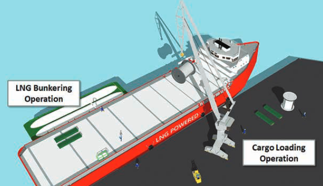
For LNG bunkering, a SIMOPS assessment would focus on how other activities could increase the likelihood or consequences of an LNG release. For example, if cargo operations are located too close to bunkering locations, cargo could be dropped on LNG piping or hoses during lifting operations, resulting in an LNG release. Another example is the risk that might be posed by operation of equipment (e. g., a crane) that is not rated for hazardous area service in close proximity to a tank vent during bunkering. The SIMOPS study should serve both to (1) identify operations that potentially threaten bunkering and (2) decide whether those operations should be prohibited or can be allowed under specific, controlled conditions.
A SIMOPS assessment addresses the following items:
- Identification and description of modes of operation.
- SIMOPS risk assessment.
- Identification and development of risk mitigation measures.
The specific mitigation measures identified in the SIMOPS assessment may be incorporated into the operations manual, standard operating procedures (SOPs), or may be managed as a separate process.
A SIMOPS assessment should be performed if the owner/operator wishes to conduct other activities, such as cargo (Figure 3) or passenger loading, while bunkering. The study should serve both to (1) identify operations that potentially threaten bunkering and (2) decide whether those operations should be prohibited or can be allowed under specific, controlled conditions.
While a SIMOPS assessment is not currently required by US regulations related to LNG facilities, the USCG may require such an analysis as part of their review of bunkering procedures. The analysis should cover: (1) identification and assessment of unique hazards posed by SIMOPS, (2) engineered controls addressing SIMOPS hazards to be included in the design, (3) administrative controls addressing SIMOPS hazards documented in the operations manual or standard operating procedures, and (4) approved operating constraints (e. g., weather conditions) under which simultaneous operations are allowed.
SIMOPS could increase the risk of LNG bunkering in a variety of ways. Table 5 introduces some of the potential effects and provides examples of how SIMOPS may increase the risk.
| Table 5. Example Effects of SIMOPS | |
|---|---|
| Potential Effects | Examples |
| Increased likelihood of LNG release | Cargo loading during bunkering affecting a vessel’s position relative to the bunkering station increasing likelihood of leaks and inadvertent disconnection of hoses. |
| Dropping of cargo on LNG loading equipment. | |
| Personnel charged with overseeing LNG bunkering could become involved or distracted by other activity increasing the likelihood of fuel tank overfill. | |
| Increased likelihood of ignition, if LNG is released | More vessel/vehicle traffic in the area related to cargo activities. |
| Increased ignition source potential due from people in the surrounding area (e. g., smoking, using devices or equipment that is not rated as intrinsically safe.) | |
| Increased consequence potential | More people in the surrounding area (e. g., passenger, crew), including those who may be unaware of LNG hazards and emergency response measures. |
| Increased congestion hindering egress in the case of a LNG release. | |
| Personnel charged with overseeing LNG bunkering could become involved or distracted by other activity resulting in delayed identification of and response to a LNG release. | |
The SIMOPS assessment should be tailored to the specific facility and scope of activities, but key steps in performing the assessment include:
1 Identify SIMOPS. Develop a detailed description of each operation addressing key elements, including:
- Summary of the activity.
- Drawings identifying the work areas, including restricted areas (e. g., electrically classified areas).
- Operational procedures (step-by-step).
- Involved personnel.
- Identification of the safety and environmental hazards.
- Identify Potential Interference between SIMOPS.
- Identify potential scenarios where other operations could impact LNG bunkering and vice versa (see Table 5 for example).
2 Assess Risk. Choose an appropriate risk assessment technique (e. g., HAZOP, What-If) and conduct the assessment.
- Assemble team of experts familiar with each activity (ship board and facility activities).
- Provide an overview of each activity, including major steps of the operation.
- Brainstorm hazards that could arise from SIMOPS.
- Identify potential causes of the hazard.
- Identify safeguards potentially in place to prevent the likelihood of occurrence (prevention) or minimize the consequences (mitigation).
- Describe the consequences, and if the hazard could result in a release of LNG.
- Score the risk of the hazard as a function of likelihood and consequence.
3 Develop SIMOPS Controls. For risks above tolerance thresholds, identify additional controls necessary to mitigate the risks to acceptable levels. See Section see above for examples of safeguards that could be employed to prevent and mitigate LNG release scenarios.
4 Document the results of the SIMOPS Assessment. Documentation can take a variety of forms, including developing a separate SIMOPS manual or incorporating SIMOPS into operations manual/SOPs. The documentation should address key areas such as:
- Organizational roles and responsibilities.
- Description of the SIMOPS.
- SIMOPS SOPs.
- Operating conditions/limits for SIMOPS.
- Change control process.
- Communication plan.
- Contingency plan.
Fire Risk Assessment
A FRA characterizes the fire risk at an LNG terminal by identifying fire scenarios of interest, their likelihood of occurrence, and their potential consequences. The purpose of an FRA for an LNG bunkering terminal is to estimate the level of risk present and, if necessary, identify measures (e. g., firefighting equipment) to reduce risk to an acceptable level. For example, if a bunkering facility does not believe that the fire protection requirements defined in NFPA 59A and 33 CFR 127 are appropriate or necessary for their operation, an FRA would allow them to define and document their approach for fire protection and submit it to the appropriate regulator (e. g., USCG, fire marshal, or other authority having jurisdiction).
If an FRA is required for a facility, the owner/operator should follow recommended guidelines, such as SIGTTO’s A Risk Based Approach for the Evaluation of Firefighting Equipment on Liquefied Gas Jetties or NFPA 551: Guide for the Evaluation of FRAs in the Development of the FRA.
FRAs may employ a variety of methods to characterize the likelihood and consequences of fire scenarios as described below. If an approach includes the effects of fire protection, both the effectiveness and reliability of such systems should be considered. Before using an approach, the facility should first confer with the appropriate regulators to ensure they are willing to consider the FRA outcome as a basis for defining required fire protection.
Qualitative Methods: Qualitative methods do not typically quantify the consequences or likelihood of fire events. Qualitative methods include what-if, risk matrices, risk indices, and fire safety concepts tree approaches. These methods are useful for generating fire scenarios used in other more quantitative approaches described below.
Semi-quantitative Methods: Semi-quantitative methods quantify either the likelihood or consequence of a fire event. Methods that calculate likelihood include actuarial/loss statistical analysis and stand-alone event tree analysis. Methods that calculate consequence include outdoor and enclosure fire models of various complexity.
For the commonly used event tree analysis approach, the likelihood of fire event outcomes will be based on the frequency of the originating event (i. e., a leak due to mechanical failure, human error, or intentional release) and the probabilities associated with the independent event tree branches. Branches may include actions which increase the consequences (i. e., ignition, wind direction, equipment congestion) as well as mitigate the consequences (i. e., firefighting resources, liquid containment). The termination of each branch leads to one or more outcomes for which the likelihood is the originating frequency multiplied by all the probabilities leading to the branch termination. Possible outcomes for LNG terminals include jet fires, pool fires, flash fires from flammable vapor clouds, boiling liquid expanding vapor explosions (BLEVE), rapid phase transitions (RPT), and cryogenic liquid injuries.
Semi-quantitative methods which calculate consequences typically use a fire model to determine the hazards. Many different fire models exist for various fire types including:
- jet;
- pool;
- flash;
- and enclosure fires.
Additionally, the fidelity of fire models range from simple analytical models to complex, numerical computational fluid dynamics (CFD) models. Fire models for LNG terminals typically include jet and pool fire models and flash fire (dispersion) models. Flash fire models rely on dispersion modeling to calculate the size of the flammable vapor cloud. Use of dispersion models for LNG should consider the material specific flashing and jetting behavior. Some Authorities Having Jurisdiction require specific modeling parameters when doing LNG dispersion modeling.
Simple jet and pool fire models will include discharge calculations which determine the leak rate and properties of LNG after the orifice followed by a model of the fire which depends on a geometric approximation of the fire shape. For jet fires, a cone shape or a series of frustums is used while for pool fires a tilted cylinder is typically used. The size of the assumed geometry is dependent on the discharge leak results combined with published analytical and semi-empirical relations (The Netherlands Organization yellow book, Center for Chemical Process Safety publications) for different fire orientations (i. e., horizontal jet, vertical jet, circular pool). Finally, using the assumed geometry and view factor calculations, thermal radiation values at targets can be determined. The models which implement the above features are typically included as part of a consequence modeling software package and they require moderate user experience and have runtimes measured in seconds to minutes.
More complex CFD models are appropriate when simple models have shown an unacceptable hazard and site specific features not captured in the simple models may influence the results. Features such as pool containment, drainage, local wind patterns, and structures/vessels can be more accurately included in CFD models which rely on a 3D model of the site. Multiple free and commercial CFD codes are capable of modeling fire hazards. These tools require a high degree of user experience and have runtimes of hours to days.
Quantitative Methods: Fully quantitative methods calculate both the likelihood and consequence of a fire event. Methods used should be validated and any numerical routines should undergo verification. Methods that can be used when performing a fully quantitative FRA include a rigorous calculation of risk from each fire scenario including all the possible outcomes indicated by the event tree and their likelihoods as well as simpler approaches which set a consequence limit and then sum the frequency from all events which exceed this limit and compare to the agreed upon criteria for frequency of unacceptable consequences. The rigorous approach is similar to a QRA where the risk of injury or death is calculated as the combination of likelihood and consequence. Total risk is the summation of the risk from each fire scenario outcome (i. e., jet fire, pool fire, etc.). The risk calculation may also require an estimate of the exposure time of personnel and the number of people exposed to accurately calculate maximum individual and aggregate risk measures, which can then be compared to agree upon criteria. Full QRA analysis can involve many fire scenarios of various magnitudes and involves a large amount of calculations. Such analyses are typically performed using specialized software to manage the complexity.
Cost-benefit Methods: Cost-benefit methods are computational models that incorporate probability, consequences, and cost data in an integrated manner. They include the risk of injury or death calculated in the full quantitative risk analysis approach above while adding an additional parameter, the cost of the fire in terms of both fire prevention costs and maintenance as well as the cost of damage associated with an event. This allows owners/operators to optimize the fire protection design while providing the necessary level of protection to reach life safety risk criteria.
Waterway Suitability Assessment
USCG Navigation and Vessel Inspection Circular (NVIC) No. 01-2011 requires owners/operators of LNG terminals to conduct a WSA to assess safety and security risks associated with LNG vessel operations within the port and, if necessary, recommend strategies to mitigate the identified risk. LNG bunkering facilities, while likely to store significantly less quantities of LNG when compared to import/export terminals, will likely be required to perform a WSA or at least a streamlined WSA, particularly if the bunkering will be supplied with LNG via bulk marine transport (e. g., LNG in bulk via LNG carriers or barges). Note: the WSA development is the responsibility of the LNG facility as per 33 CFR 127.
Full scope WSA’s are risk-based assessments that address the following items:
Port characterization which includes:
- identification and descriptions of industrial areas;
- areas that are environmentally sensitive;
- populated areas;
- critical areas (military or otherwise areas of national significance) and overall port description including any regulated navigation areas;
regulations specify that these areas are to be identified at a minimum, 15 miles (25 km) from the LNG facility along the transit route that the LNG vessel will be using.
Factors adjacent to the facility such as:
- Depths of the water.
- Tidal range.
- Protection from high seas.
- Natural hazards, including reefs, rocks, and sandbars.
- Underwater pipelines and cables.
- Distances of berthed vessels from the channel.
- Other safety and security issues identifie.
LNG Vessel: Vessel descriptions should include both the LNG cargo vessels and vessels using the facility to bunker. Most projects will not have a full understanding of these vessels since most are just now being developed. At a minimum, information should include the expected flag of vessels and vessel particulars (length, breath, depth, capacity of cargo and or fuel) LNG tank description, firefighting capability, and vapor control capability. If some of the information is not known a statement that indicates as information is known will be furnished to the COTP. If the vessel is going to be US flagged it should be stated that the vessel will conform to all US design, construction, documentation and inspection regulations. If foreign flagged, it should be stated that the vessel will conform to Flag, Class and international requirements for a LNG carrier.
Characterization of the LNG bunkering facility and vessel routes: The facility description should include:
- mode of arrival of the LNG (i. e., pipeline, truck, barge);
- description of storage;
- description of piping (i. e., Maximum Allowable Operating Pressure, length, diameter);
- description of transfer dock and transfer mode (i.e., loading arm, hose);
- firefighting capabilities and a statement that the facility will meet MTSA requirements.
For vessel route (mode of arrival of the LNG bulk vessels only) information should include the populated areas (medium/high people per square mile areas as described in the NVIC), environmental sensitive areas, description of bridges and tunnels over and under the waterway.
Risk assessment for maritime safety and security: The NVIC has specific safety and security scenarios that should be included for all risk assessments. These scenarios are designed specifically for the LNG carrier’s transit and while docked at the facility. The NVIC does not include specific scenarios for the transfer or storage of LNG on the facility. The COTP should be consulted for their specific requirements for those items.
Risk management strategies: The NVIC describes specific risk mitigation strategies in a USCG controlled attachment to the document, however, due to security reasons those strategies will not be discussed in this document.
Resource needs for maritime safety, security and response: These should include, fire, medical and law enforcement in the area and their capabilities to respond to an LNG incident, and a gap analysis of resources that are needed for an adequate response. These resources can include training, equipment, or public education/relations.
In current bunkering projects, requirements for what are being called WSAs are simpler reviews (i. e., streamlined WSAs) that are actually more like project HAZID studies. It is recommended that discussions with the USCG staff in the port area be initiated well before a WSA is drafted for submission so expectations for the WSA can be defined (see policy letter 02-15).
WSAs are submitted to the local COTP for review. The COTP then passes the WSA and USCG recommendations regarding safety and security measures to the agency providing permits for the project. That agency may vary, depending on the nature of the facility and state and local requirements.
Process Hazards Analyses
PHAs are a class of study that industry very commonly uses for processes that handle hazardous materials and are required by the US regulations that mandate process safety management (OSHA 29 CFR 1910.119) and risk management (EPA 40 CFR 68). They are also addressed in Chapter 15 of NFPA 59A.
PHAs, which are sometimes referred to as HAZOP studies or HAZID studies, involve a multidisciplinary team using detailed engineering information to consider the hazards of the «process», where process can be specific equipment or operations. Depending on the specific methodology used (e. g., what-if, failure modes and effects, HAZOP) the team will document what can go wrong, potential causes and consequences of that event, and what safety measures prevent or mitigate the event. Any recommendations from the PHA are then forwarded for consideration by project personnel completing the design, or planning the operations, maintenance, and emergency response activities for the facility to which the process belongs.
The typical project tasks for conducting a PHA consist of the following:
Collect data for the analysis. Prior to the analysis workshops, compile the following information:
- Process flow diagrams (these must indicate approximate process conditions).
- MSDSs (and other pertinent chemistry data) for chemicals involved in the process.
- Piping and instrumentation diagrams (P&IDs).
- Design temperatures and pressures for major equipment (these data should be compiled if not shown on the P&IDs).
- Pump/compressor curves and maximum (blocked) discharge pressures.
- Materials of construction for equipment and interconnected piping (if not indicated on the
P&IDs). - Plot plan (and/or equipment arrangement drawings) with general equipment layout and elevations.
- Standard operating procedures (SOPs) for normal operations, as well as procedures for startup, shutdown, sampling, emergency shutdown, and any on line maintenance.
- Safe work practices and permits/authorizations.
- Emergency procedures (if they exist).
- Incident reports for the specific unit (or similar units if the unit is a new installation) filed in the past 5 years of process operations.
In addition, the following information may be helpful as reference materials during the hazard evaluation meetings:
- Electrical classification drawings/information.
- Equipment testing/inspection plans.
- Process alarm setpoint data, as well as logic/ladder diagrams or loop sheets for complex safety instrumented systems.
- Relief system design basis (including set pressures and relief capacity sizing basis for relief
devices). - Ventilation system design data.
Conduct the hazard evaluation meetings. The objectives of these meetings (1) provide an orientation for the PHA team members, explaining the technique to be used and the ground rules for team meetings, (2) perform a hazard evaluation of facility items (process sections, equipment failures, etc.), (3) perform a facility/stationary source siting and human factors review and (4) review incident reports that apply to the scope of the PHA.
Prepare a PHA report. Document the analysis including process descriptions, analysis protocol and methodology descriptions, and a detailed meeting summary table.
Sources of LNG and Project Implementation to Make LNG Available for Use as a Marine Fuel
Potential LNG Supply Sources
This section outlines the various types of LNG facilities for the bunkering of marine vessels in the US and Canada that are:
- Currently in operation or under construction.
- Proposed and undergoing design review/approval.
- Potential locations as a supplier of LNG.
In addition to describing the various types of facilities, this section also lists known, proposed and potential sites currently announced for LNG supply to marine users. It should be noted that the market for supply of LNG to nontraditional users (e. g., fixed facilities, trucks, and marine shipping) is changing rapidly, so the examples provided in this study will change with many new suppliers expected to enter the market. The information on the companies and facilities described here represents ABS experience with ongoing LNG bunkering projects, long-term involvement in LNG activities, and consultation with leading companies in ongoing bunkering projects. The study also uses information drawn from media accounts, conference presentations, and discussions with a wide variety of people involved in the LNG business (including bunkering facility developers and gas-fueled ship operators). However, because of the rapid changes the LNG bunkering business is undergoing, this information will most definitely change.
The types of facilities that may provide LNG fuel include:
- Existing LNG import facilities.
- Proposed LNG export facilities.
- Existing LNG peakshaving/satellite facilities
- Existing and proposed liquefaction facilities supporting highway, heavy equipment, and rail markets.
- Proposed bunkering facilities with liquefaction processes.
- Proposed bunkering facilities supplied via trucks/transportation containers.
FERC has indicated that it will not be licensing LNG Developing LNG Bunkering Facilities in Ports: Governance and Good Practicebunkering facilities; however, licenses issued by FERC for facilities developed for other purposes (e. g., import and export terminals) may need to be amended to reflect bunkering or truck loading activities, if such operations are added after facility approval.
This section describes each of these types of facilities and how they may be pertinent to the growth of LNG bunkering. Also, Appendix C to this study provides a summary of information regarding interest in LNG bunkering and specific bunkering projects or activities in each maritime region of the US and Canada.
APPENDIX C – Summary of Regional Bunkering Infrastructure
| Table. Summary of Regional Bunkering Infrastructure | ||||
|---|---|---|---|---|
| Region | LNG Availability | Existing Infrastructure | Market Interest | LNG Bunkering Projects in Process |
| United States, Pacific Coast, Alaska and Hawaii | Very Limited (because of proximity and accessibility to waterways | According to PHMSA there are ten peak shaving facilities in the west coast states that are connected to natural gas pipe line According to FERC there is one export facility in Alaska | High/Moderate The Pacific Coast of the United States, including Alaska and Hawaii, is showing relatively high to moderate interest in the use of LNG as a marine fuel. In particular, the Seattle/Tacoma region where there is high interest in LNG | PSE’s plans to break ground on a LNG facility summer of 2015. The facility will supply LNG to vessels as a marine fuel. The facility will also supply LNG to over-the-road vehicles TOTE progressing with planned conversion of its two Orca Class RO/RO cargo ships with service between Washington and Alaska Washington State Ferries recently submitted a WSA for the proposed conversion of six of the Issaquah class ferries to LNG. HECO is looking into the possible use of LNG as lower cost alternative for power generation and as a cleaner fuel source to comply with environmental standards. |
| United States, Gulf Coast | Very Good | According to FERC there are six approved LNG export terminals on the Gulf Coast. According to PHMSA there are 4 peak shaving facilities in Gulf Coast states. | High/Moderate The Gulf Coast region has | Harvey Gulf International Marine currently constructing an LNG bunkering facility in Port Fourchon, LA for OSVs in the oil and gas industry. Tenaska NG Fuels proposes to construct a LNG facility along the New Orleans-Baton Rouge Mississippi River corridor. LNG America has an agreement with Buffalo Marine Service, Inc. to design an LNG bunker fuel network for the Gulf Coast region. |
| United States, Atlantic Coas | Good | According to FERC there are three approved LNG export terminals on the Atlantic Coast. According to PHMSA there are 25 peak shaving facilities in the Atlantic Coast states. | Low/Moderate The North Atlantic region low interest. The Middle Atlantic region moderate level of interest.The South Atlantic region moderate level of interest (except Florida which is High). | WesPac Midstream, Pivotal LNG, and TOTE in the Port of Jacksonville jointly developing LNG bunkering project. TOTE is constructing two new LNG fueled ships for service between Jacksonville, FL and San Juan, PR.Crowley Maritime awarded two multi-year contracts to supply containerized LNG to major manufacturing facilities in Puerto Rico from the Port of JacksonvilleFlorida East Coast Industries proposes to build a LNG facility near Titusville, FL that may in future have marine bunkering facilities. |
| United States, In-Land Rivers and Great Lake | Very Limited (because of proximity and accessibility to waterways) | According to PHMSA there are 21 peak shaving facilities in the states that have access to the major inland rivers or the Great Lakes. | Moderate/Low The Great Lakes region is showing moderate to low interest in LNG bunkering operations. There appears to be little opposition to LNG in the region but most projects have not moved beyond consultation | BLU LNG, currently has two LNG bunkering permits under review for Duluth and South Lake Michigan. |
| Canada, Atlantic Coast | Very Limited | There is no existing LNG infrastructure | Moderate There are two proposed LNG facilities in Guysborough, Nova Scotia, and one in Port Hawkesbury, Nova Scotia. Discussions with local stakeholders and authorities in Nova Scotia indicate that public sentiment is very favorable to LNG | No LNG bunkering specific project in process |
| Canada, Pacific Coas | Good | Fortis BC Energy operates the Tillbury Island LNG facility near Vancouver BC. Fortis BC currently uses this facility to provide gas supplies during periods of peak demand. However, the facility does not have a marine terminal. | Moderate/High In British Columbia there are numerous proposed LNG export terminals being discussed. These include projects in Kitimat, BC; Douglas Channel LNG, LNG Canada, Kitimat LNG, WCC LNG, Triton LNG and Cedar LNG. Also in the Prince Rupert area; Orca LNG, Grassy Point LNG, Aurora LNG, Triton LNG, Pacific Northwest LNG, Prince Rupert LNG and WCC LNG. Other notable projects being discussed include Woodfibre LNG in Squamish, BC, the Kitsault Energy Project in Kitsault, BC. | WesPac Midstream – Vancouver LLC (WPMV), a subsidiary of WesPac Midstream LLC (WesPac), is partnering with Fortis BC to use the Tillbury Island LNG facility which is located south of Vancouver, BC, on the Fraser River for LNG bunkering operations. BC Ferries is converting two Spirit Class vessels to LNG, and also building three dual fuel intermediate class vessels scheduled for delivery in 2016 and 2017. Seaspan Ferries Corporation, a unit of Vancouver-based Seaspan Marine Corporation, has awarded a contract for the construction of two LNG-powered ferries equipped with dual-fuel engines. |
| Canada, Central Water-ways and Great Lakes | Limited | Gaz Métro LNG has a liquefaction, storage and regasification plant in Montreal, QU. | Moderate Mostly centering on Ontario and Quebec, overall LNG interest in the region can be moderate Royal Dutch Shell proposed LNG facility in in Sarnia, Ontario has been temporarily put on hold | GAZ Metro will be supplying Quebec ferry company Société des Traversiers du Québec (STQ), with LNG from trucks for three LNG fueled ferries to be operated by STQ. The first bunkering operation to happen spring of 2015 |
LNG Import Facilities
LNG import facilities generally receive LNG by vessel, transfer it to onshore storage tanks, and vaporize it into a natural gas pipeline for transmission to customers’ distribution networks. These types of facilities were initially built in the US in the 1970s at the Everett (Boston, Massachusetts), Cove Point (Cove Point, Maryland), Elba Island (Savannah, Georgia), and Lake Charles (Louisiana) terminals. Table 6 lists all of the existing import/export terminals (as of January 6, 2015) in the US and Canada.
| Table 6. Currently Operating North American LNG Facilities with Maritime Access | ||||
|---|---|---|---|---|
| Terminal | Location | Owners and/or Operators | Year Service Began | Notes |
| Atlantic Coast | ||||
| Canaport LNG | St. John, NB | Repsol/Irving Oil | 2009 | 1,2 Bcfd Receiving and Regasification terminal |
| Distrigas LNG Terminal | Everett (Boston), MA | Distrigas of Massachusetts, LLC | 1971 | Includes large LNG truck operation to satellite peakshavers and other customers. See below. |
| Northeast Gateway LNG | Offshore, MA | Excelerate Energy | 2007 | Deepwater import facility 13 miles from shore can receive 0,6 Bcfd. Pipeline delivers to US markets. |
| Neptune LNG | Offshore, MA | GDF Suez | 2009 | Deepwater import facility 10 miles from shore can receive 0,4 Bcfd. Pipeline delivers to US markets. |
| Cove Point LNG | Cove Point, MD | Dominion CP LNG | 2003 | Suspended ops in 1970. Resumed ops in 2003. New facility construction begun October 2014. |
| Elba Island LNG | Savannah, GA | El Paso Energy | 2003 | Includes proposed liquefaction project and export facility. |
| Gulf Coast | ||||
| Gulf LNG | Pascagoula, MS | El Paso (Kinder Morgan)/Crest/ Sonango | 2011 | Existing import capability. Liquefaction and export facility scheduled 2019/2020. |
| Lake Charles | Lake Charles, LA | Southern Union- Trunkline LNG | 1981 | Export facility scheduled 2019 |
| Cameron LNG | Hackberry, LA | Sempra | 2009 | Approved by DOE to re-export delivered LNG. DOE approved to export 1,7 Bcfd domestic LNG scheduled 2018 |
| Sabine Pass LNG | Cameron Parish, LA | Cheniere | 2008 | Approved by DOE to re-export delivered LNG. Export terminal with liquefaction process under construction. |
| Golden Pass LNG | Sabine Pass, TX | Qatar Petroleum/ ExxonMobil/ ConocoPhillips | 2010 | 2,0 Bcfd importing capability. Proposed to add exporting capability. |
| Freeport LNG | Freeport, TX | Cheniere | 2008 | Expanded import terminal approved, but not under construction. 2,0 Bcfd Liquefaction plant for LNG export approved by FERC July 2014, now under construction. |
| Alaska | ||||
| Point Nikiski LNG | Kenai, AK | Conoco Phillips | 1969 | Operated as an export terminal for more than 40 years and was mothballed in 2012. In December 2013, the company applied to restart the facility to resume exports and support gas development in Alaska. That application was approved in February 2014. |
The table also indicates which of them have been approved to re-export LNG that has been previously imported (see below for a discussion of export terminals). Most of these facilities have applied for, been approved or are constructing liquefaction and export facilities (see the Notes section of the table).
The interest in new LNG import facilities has decreased from 40 proposed facilities in 2008 to 2 listed by FERC as of January 6, 2015 that are still pursuing licenses and 2 additional potential sites. These locations are:
Proposed sites:
- Downeast LNG (Robbinston, ME).
- Oregon LNG (Astoria, OR).
Potential sites:
- Kestrel Energy – Downeast LNG (Robbinston, ME).
- Liberty Natural Gas (Port Ambrose, located off the NY coastline – LNG is not provided on shore).
As of January 6, 2015, there are no approved Import terminals currently under construction in the US only two facilities, Downeast LNG and Port Ambrose are under consideration because they are located where they can supply natural gas to regions of the US that are not currently adequately served by natural gas pipelines (compared to the local or regional natural gas demand). Which of these facilities will be built will depend on successful approval and financing for further project development.
Although the amount of fuel needed for bunkering in most ports is relatively small compared to the capacity of most import terminals, such facilities are potentially pertinent to marine bunkering activities because they represent a potential source of LNG. From the table it is apparent that there is a move to liquefaction and export at existing import facilities which may provide additional marine fueling opportunities. In addition, some of the LNG import facilities already supply LNG to customers via LNG trucks (e. g., the Distrigas LNG Terminal in Massachusetts). Historically, truck transportation of LNG has been used extensively for supplying LNG satellite peakshaving facilities (see below for more details), but there is the potential for merchant sales of LNG from import terminals. See below for a discussion of such supply offers.
Bunkering project developers need to be aware that proposals for transportation of LNG by truck have not always been well received. It was opposed by a variety of local groups in Savannah in 2010 when the Elba Island LNG Terminal proposed distributing LNG by trucks that would pass through portions of the city of Savannah. The discussion of safety issues associated with that operation continued until 2012 when the terminal decided to abandon the proposal.
LNG Export Facilities
With the increase in domestic natural gas supplies, DOE is reviewing or has approved approximately 50 applications to export LNG. Following DOE approval they will be reviewed by FERC to approve the specific design from a safety, reliability, and environmental impact view point. If approved and built, these facilities will (1) be supplied with natural gas by pipeline and (2) include liquefaction systems to produce LNG and store it in onshore tanks or near shore floating facilities for some designs. Table 7 provides a list of proposed/potential US LNG export terminals. Table 8 provides a list of proposed/ potential Canadian export terminals.
| Table 7. Current Summary of Proposed/Potential US LNG Export Terminals | ||||||
|---|---|---|---|---|---|---|
| Company | Location | Export Quantity | Project Status | |||
| Application Approved by DOE | Under Review by FERC | Approved by FERC | Under Construc- tio | |||
| Kestrel Energy – Downeast LNG | Robbinston, ME | 0,5 Bcfd | ✔ | ✔ | ||
| Liberty Natural-Port Ambrose | Offshore NY | 0,4 Bcfd | ||||
| Dominion – Cove Point LNG | Cove Point, MD | 1,0 Bcfd FTA 0,77 Bcfd Non FTA | ✔ | ✔ | ✔ | |
| Southern LNG Company | Elba Island, GA | 0,35 Bcfd | ✔ | ✔ | ||
| Eagle LNG Partners | Jacksonville, FL | 0,75 Bcfd | ✔ | ✔ | ||
| Carib Energy (USA) LLC | Martin Cty, FL | 0,3 Bcfd FTA .0,4 Bcfd Non FTA | ✔ | |||
| Advanced Energy Solutions, LLC | Martin City, FL | 0,02 Bcfd | ✔ | |||
| Floridian Natural Gas Storage | Indiantown, FL | 0,02 Bcfd | ✔ | ✔ | ||
| Gulf LNG Liquefaction | Pascagoula, MS | 1,5 Bcfd | ✔ | ✔ | ||
| Freeport-McMoRan Energy LLC | Offshore LA | 3,22 Bcfd | ✔ | |||
| Sabine Pass Liquefaction / Cheniere | Sabine Pass, LA | 2,2 Bcfd | ✔ | ✔ | ✔ | |
| Sabine Pass Liquefaction LLC | Sabine Pass, LA | 0,28 Bcfd | ✔ | |||
| Sabine Pass Liquefaction LLC | Sabine Pass, LA | 0,24 Bcfd | ✔ | |||
| Sabine Pass Liquefaction LLC | Sabine Pass, LA | 0,86 Bcfd | ✔ | ✔ | ||
| Sabine Pass Liquefaction LLC | Sabine Pass, LA | 0,54 Bcfd | ✔ | ✔ | ||
| Lake Charles Exports, LLC | Lake Charles, LA | 2,0 Bcfd | ✔ | ✔ | ||
| Cameron LNG, LLC | Hackberry, LA | 1,7 Bcfd | ✔ | ✔ | ✔ | |
| Cameron LNG, LLC | Hackberry, LA | 4,2 Bcfd | ||||
| Louisiana LNG Energy LLC | Plaquemines Parish, LA | 0,30 Bcfd | ✔ | ✔ | ||
| SB Power Solutions | 0,07 Bcfd | ✔ | ||||
| Main Pass Energy Hub, LLC | Gulf of Mexico | 3,22 Bcfd | ✔ | ✔ | ||
| CE FLNG, LLC | Plaquemines Parish, LA | 1,07 Bcfd | ✔ | ✔ | ||
| Magnolia LNG | Lake Charles, LA | 1,07 Bcfd | ✔ | ✔ | ||
| Southern Union- Trunkline LNG | Lake Charles, LA | 2,2 Bcfd | ✔ | ✔ | ||
| Delfin LNG LLC | Gulf of Mexico (off Cameron Parish) | 1,8 Bcfd | ✔ | |||
| SCT&E LNG | Cameron Parish, LA | 1,60 Bcfd | ✔ | |||
| Waller LNG Services, LLC | Cameron Parish, LA | 0,16 Bcfd 0,19 Bcfd Non FTA | ✔ | ✔ | ||
| Gasfin Development | Cameron Parish, LA | 0,20 Bcfd | ✔ | ✔ | ||
| Venture Global Calcasieu Pass, LLC (Former Venture Global LNG, LLC) | Cameron Parish, LA | 1,34 Bcfd | ✔ | ✔ | ||
| Freeport LNG Dev/ Freeport LNG Expansion/FLNG Liquefaction | Freeport, TX | 2,8 Bcfd FTA 0,4 Bcfd Non-FTA | ✔ | ✔ | ✔ | |
| ExxonMobil – Golden Pass | Sabine Pass, TX | 2,1 Bcfd | ✔ | ✔ | ||
| Excelerate Liquefaction | Lavaca Bay, TX | 1,38 Bcfd | ✔ | ✔ | ||
| Cheniere – Corpus Christi LNG | Corpus Christi, TX | 2,1 Bcfd | ✔ | ✔ | ||
| Argent Marine Management Inc | Trussville, AL | 0,003 Bcfd | ||||
| Eos LNG & Barca LNG | Brownsville, TX | 3,2 Bcfd | ✔ | |||
| Gulf Coast LNG Export | Brownsville, TX | 2,8 Bcfd | ✔ | ✔ | ||
| Annova LNG LLC | Brownsville, TX | 0,94 Bcfd | ✔ | |||
| Texas LNG LLC | Brownsville, TX | 0,27 Bcfd | ✔ | |||
| WestPac/Gulfgate Terminal | Port Arthur, TX | 0,2 Bcfd | ||||
| Next Decade | Galveston, TX | 0,77 Bcfd | ||||
| Next Decade Partners, LLC, (former Pangea LNG (North America) Holdings, LLC) | Ingleside, TX | 1,09 Bcfd | ✔ | ✔ | ||
| Alturas LLC | Port Arthur, TX | 0,2 Bcfd | ||||
| Strom Inc. | Starke,FL | 0,08 Bcfd | ||||
| Strom Inc. | 0,02 Bcfd | |||||
| Strom Inc. | 0,02 Bcfd | |||||
| Air Flow North America Corp | 0,002 Bcfd | |||||
| American LNG Marketing, LLC | 0,008 Bcfd | |||||
| LNG Development Company LLC (d/b/a Oregon LNG | Astoria, OR | 1,25 Bcfd | ✔ | ✔ | ||
| Jordan Cove Energy Project | Coos Bay, OR | 1,2 Bcfd FTA 0,8 Bcfd Non FTA | ✔ | ✔ | ||
| ExxonMobil, ConocoPhillips, BP, TransCanada and Alaska Gasline | Nikiski, AK | 2,55 Bcfd | ✔ | |||
Table 8 provides a list of proposed/ potential Canadian export terminals.
| Table 8. Proposed/Potential Canadian LNG Export Terminals | ||
|---|---|---|
| Project | Location | Approved by National Energy Board |
| KM LNG Operating General Partnership – 0,7 Bcfd | Kitimat, BC | ✔ |
| BC LNG Export Co-operative LLC – 0,23 Bcfd | Kitimat, BC | ✔ |
| LNG Canada Development Inc – 3,23 Bcfd | Kitimat, BC | ✔ |
| Apache Canada Ltd – 1,28 Bcfd | Kitimat, BC | |
| Pacific NorthWest LNG Ltd.- 2,74 Bcfd | Prince Rupert Island, BC | ✔ |
| WCC LNG Ltd. | Kitimat or Prince Rupert, BC | ✔ |
| Prince Rupert LNG Exports Limited – 2,91 Bcfd | Prince Rupert Island, BC | ✔ |
| ExxonMobil – Imperial – 4,0 Bcfd | Prince Rupert Island, BC | |
| Woodfibre LNG Export Pte. Ltd. – 0,29 Bcfd | Squamish, BC | ✔ |
| Jordan Cove LNG L.P. | Kingsgate, BC – Eastport, ID Huntingdon, BC – Sumas, WA | ✔ |
| Triton LNG Limited Partnership – 0,32 Bcfd | Kitimat or Prince Rupert Island, BC | ✔ |
| Pieridae Energy Ltd(Goldboro LNG) – 1,4 Bcfd | Guysborough County, NS | |
| H-Energy – 1,8 Bcfd | Melford, NS | |
| Aurora Liquefied Natural Gas Ltd. – 3,12 Bcfd | Prince Rupert Island, BC | ✔ |
| Orca LNG – 3,2 Bcfd | Prince Rupert Island, BC | |
| Kitsault Energy Ltd. – 2,7 Bcfd | Kitsault, BC | |
| Canada Stewart Energy Group – 4,1 Bcfd | Stewart, BC | |
| WestPac Midstream Vancouver – 0,4 Bcfd | Delta, BC | |
| Steelhead LNG – 0,11 Bcfd | Vancouver Island, BC | |
| Woodside Energy Holdings Pty Ltd. | Northwest Coast | |
| Quicksilver Resources Canada Inc. | Vancouver Island, BC | |
| Cedar 1, 2, 3, LNG Export Ltd. | ||
| GNL Quebec Inc – 1,6 Bcfd | Saquenay, Quebec | |
| Bear Head LNG – 0,5 Bcfd | Port Hawkesbury,NS | |
| Oregon LNG Marketing Company LLC | Kingsgate, BC – Eastport, ID Huntingdon, BC – Sumas, WA | ✔ |
As shown in Table 7, most of the proposed US export facilities are on the Gulf Coast, so they will not contribute significantly to bunkering projects in the Northeast or on the West Coast. There is discussion of possible supply to the US northwest ports from Canadian export facilities, if market demand there is not met by US suppliers. Also, both DOE and energy industry analysts agree that not all of the export facilities will be built. However, facilities that are built may provide additional locations where LNG can be offered for marine vessel bunkering. Export facilities will always be located with marine access because they will be shipping LNG for export via LNG carriers and/or barges.
Some examples of LNG bunkering facilities are:
The Magnolia LNG Export Terminal proposed at Lake Charles, Louisiana, now under review by FERC, includes the loading of bunkering vessels (e. g., bunkering barges or ships) as part of its currently proposed design. Given the scale of a liquefaction and shipping facility required for large scale Indonesia LNG Export Companies – Infrastructure, Trends, and Future ProjectsLNG export, addition of bunkering capability should be a relatively small increase in project scope and cost and may well be considered by other export projects.
Also, Cheniere Energy has an agreement in principle to supply LNG from its Sabine Pass LNG Export facility currently under construction in Cameron Parish, Louisiana, to LNG America. LNG America will distribute LNG in the greater Gulf Coast region and plans to expand to other regions as commercial agreements are completed. It recently signed a contract with Jensen Maritime, Crowley Maritime Corporation’s Seattle-based naval architecture and marine engineering company, to design the initial bunker/shuttle barge for its Gulf Coast operations. The vessels have an initial planned capacity of up to 3 000 m3 of LNG. Once in operation, the bunker barges will serve the dual purpose of moving LNG from the supply source to coastal-based storage and distribution terminals, as well as directly bunkering large ships.
Peakshaving Facilities
Peakshaving facilities serve to collect and store LNG during times of low natural gas demand and then regasify the LNG to go into the local or regional natural gas network. There are about 100 LNG peakshaving facilities in the US they are either: (1) facilities that have liquefaction systems to take natural gas off a pipeline and make LNG that can be stored, or (2) «satellite facilities» that are provided LNG by truck that is then stored. In either case, they have regasification equipment that allows them to supply natural gas to the network during subsequent periods of high demand (e. g., winter heating season).
There are about 100 of these facilities located across the US, often in locations where natural gas is not produced and the natural pipeline infrastructure is not adequate to bring natural gas into the region to meet peak demands. For example, there are a large number of peakshaving facilities in the Northeast because of limited access to natural gas pipeline capacity because of the distance from the primary gas supplies (primarily along the Gulf Coast). In Canada, there are also peakshaving facilities located in Quebec, Ontario, and British Columbia.
Like import terminals, peakshaving facilities that have their own liquefaction equipment may be sources of LNG to support marine bunkering in their region. It is less likely that satellite facilities that only receive LNG by truck are potential suppliers of LNG. In that situation, it would generally make sense to ship LNG by truck only once, directly from the liquefaction location to the ultimate users.
As described see below, AGL Resources is an example of a company with existing peakshaving facilities that intends to supply LNG to the marine fuel market. It has acquired a network of LNG storage facilities in the southeastern US (Alabama, Georgia, Tennessee and Virginia) and, through Pivotal LNG (a wholly owned subsidiary), is marketing LNG for delivery by truck to companies needing natural gas fuel. The AGL facility in Trussville, Alabama, has been mentioned as a potential supplier to LNG bunkering facilities along the US Gulf Coast.
LNG Fuel Distribution Facilities for Other Transportation Modes
There are numerous other applications for LNG as a fuel that are not marine-related. These include:
- Fueling of vehicle fleets operating out of fixed locations (e. g., buses, garbage trucks, mining vehicles).
- Fueling of trucks operating fixed routes of specific lengths (e. g., package delivery services).
- Long-haul trucking operations that fuel at truck stops.
LNG usage by these industrial sectors is expanding rapidly, so participants are sponsoring liquefaction facilities regionally in order to serve cross-country needs. Three of the organizations that are planning LNG fuel growth for the trucking industry (and other users in selected areas) are:
- Clean Energy that currently plans 105 refueling stations.
- Shell/Travel Centers of America that has proposed up to 100 refueling locations.
- Gaz Métro LNG has a liquefaction, storage, and regasification plant in Montreal, Quebec currently servicing other transportation modes.
Clean Energy. For its approach to the market, Clean Energy is participating in a consortium called Eagle LNG that includes:
- Clean Energy Fuels Corp.;
- Ferus Natural Gas Fuels;
- General Electric (GE) Ventures and GE Energy Financial Services.
Their intent is to provide an end-to-end solution (i. e., gas supply, liquefaction, transport if required, and fuel transfer) for the markets they will serve. They believe their experience in introducing LNG to new customers and communities in the highway fuel market has prepared them for similar issues in the marine fuel business since both markets are immature and stakeholders (e. g., customers, regulators, and municipalities) need to be educated regarding LNG’s values, characteristics, and hazards. One of the first maritime facilities they are examining is one proposed in Jacksonville, Florida to support gas-fueled cargo operations. As of December 15, 2014, FERC was reviewing the Jacksonville project proposal.
Shell/Travel Centers of America. Shell and Travel Centers of America’s plans for supplying LNG fuel to truck stops are about the same in scope as Clean Energy’s plans. They involve liquefaction facilities, LNG distribution, and storing/dispensing of LNG at truck stops. They believe it is necessary for the fuel supplier to provide the entire delivery infrastructure so trucking companies have the confidence that the LNG fuel supply network will be reliable enough for it to make sense for companies to convert their truck fleets.
Gaz Métro LNG. Gaz Métro LNG has inaugurated their first commercial LNG fuel station in Canada. This station is on the «Blue Road», which is designed to be Canada’s first LNG-fueled freight transportation corridor (located between the Quebec City and Toronto areas). In a statement released on December 11, 2014, Gaz Metro announced that it was tripling production capacity in Montreal to 9 billion cubic feet per year (0,2 Bcfd). In November 2013, Gaz Métro issued a nonbinding call for submissions for the purchase of LNG from its liquefaction plant in Montreal. Gaz Métro LNG indicated to ABS that it is interested in expanding its supply of LNG to the marine market.
Because highway refueling locations are sited for supplying cross country trucking (i. e., primarily close to interstate exits), it is not likely that the refueling locations themselves will be pertinent for marine fuel bunkering. However, to support 200 LNG service stations, there will be numerous liquefaction facilities required. LNG from those facilities transported via truck or other containers to marine users as a fuel source may meet some of the marine vessel demand. In some cases, like that proposed by Clean Energy for Jacksonville, a liquefaction facility will be built with a clear plan for supplying both the trucking and marine fuel businesses.
Examples of Proposed Bunkering Facilities
This section provides examples of proposed projects that represent the various types of proposed bunkering facilities, based on how they obtain, store, and/or bunker LNG to vessels. Example projects are used in this study to illustrate how aspects of LNG infrastructure are expected to be satisfied. This information was collected by consulting with the developers of these projects and using other sources of available information. However, none of these projects are in operation and for some there is limited information that developers are able to share due to confidentiality requirements.
These bunkering facility types are:
- Bunkering facilities with onsite liquefaction.
- Truck transportation of LNG to the storage at the bunkering facility location.
- Truck transportation of LNG for truck to vessel bunkering.
Bunkering Facilities with Onsite Liquefaction
Of the three options listed above, bunkering facilities with an onsite liquefaction process generally require the greatest investment in terms of land and process equipment. They can also provide the largest capacity and throughput. This section describes examples of this approach that have been announced.
Shell LNG Bunkering Facilities in Geismar, Louisiana and Shell Sarnia, Ontario. In 2013, Shell announced plans to bring LNG fuel to its marine and heavy-duty on-road customers in North America by investing in two small-scale liquefaction units. These two units would form the basis of two new LNG transport corridors in the Great Lakes and Gulf Coast regions. This decision followed an investment decision in 2011 on a similar corridor in Alberta, Canada. In 2013, Shell indicated the facilities would take 3 years to come into operation. Once operational, the Geismer, LA facility would supply LNG along the Mississippi River, the Intra-Coastal Waterway, the offshore Gulf of Mexico, and the onshore oil and gas exploration areas of Texas and Louisiana. In the Great Lakes corridor, Shell planned to install a liquefaction unit at its Shell Sarnia Manufacturing Centre in Sarnia, Ontario, Canada. Once operational, this project would supply LNG fuel to all five Great Lakes, their bordering US states and Canadian provinces and the St. Lawrence Seaway. The liquefaction plants each have a planned capacity of 250-million kg (250 000 tonnes) of LNG per year. In March 2014, Shell announced that these facilities are on hold while conducting a review of market demand. A recent (January 2015) contact with Shell representatives indicated that this hold is still in effect.
Waller Marine/Tenaska Facilities in Baton Rouge and Cameron Parish, Louisiana. Waller Marine and Tenaska NG Guels, LLC have announced a project to provide an integrated LNG bunkering operation in Baton Rouge and Cameron Parrish, LA that includes liquefaction facilities and a family of LNG service vessels that can provide coastwise LNG transport, unloading to storage tanks, bunkering of vessels, and regasification into a natural gas piping network. Construction is to begin in 2015 and the facility is scheduled to be operational in early 2017. Waller Marine designed bunker vessels, articulated tug barges, which will be used in conjunction with the new facilities, will be ABS classed.
Pivotal LNG/WesPac Facility in Jacksonville, Florida. Pivotal LNG, Inc. (Pivotal LNG), a wholly owned subsidiary of AGL Resources and WesPac Midstream, LLC (WesPac) announced on January 6, 2015 that they have signed a long term agreement with Totem Ocean Trailer Express (TOTE), Inc. to provide LNG to fuel TOTE’s two new state-of-the-art «Marlin-class» container ships in Jacksonville, Florida. These new dual fuel LNG container ships are expected to be delivered to the port in Jacksonville in late 2015 and early 2016.
The new Jacksonville LNG facility is expected to be operational in mid-2016.
AGL Resources, the parent company of Pivotal LNG, has more than four decades of experience in providing LNG fuel. AGL Resources is one of the largest operators of liquefaction facilities in the nation primarily through its distribution utility operations that use the LNG facilities for peakshaving services for customers when demand is highest. In addition, Pivotal LNG owns and operates a merchant LNG facility and sells LNG wholesale to truck fleets and other high-horsepower engine operators.
WesPac is a private energy infrastructure company with several small LNG facilities under development in North America. WesPac’s LNG projects are focused on high-horsepower engine applications, including:
- oil-to-gas fuel switching in power plants;
- commercial ships;
- railroad locomotives;
- and trucking.
Truck Transportation of LNG to the Storage at the Bunkering Facility Location
Harvey Gulf Port Fourchon, Louisiana. On February 14, 2014, Harvey Gulf began building a bunkering and fueling (marine and over the road) facility at Port Fourchon, LA (Figure 4) to support OSVs. The facility will have two sites, each with a capacity of 270 000 gal of LNG storage.
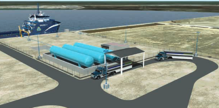
These storage tanks will be of stainless steel, Type «C» construction, featuring double-walled, vacuum-insulated construction that meets ASME Boiler and Pressure Vessel Code requirements. For LNG storage at vehicle fueling stations, the applicable requirements, detailed in Chapter 13 of NFPA, require that the storage containers be of 100 000 gal (378 000 liter [L]) capacities or less, with a maximum aggregate storage capacity at a single fueling facility of 280 000 gal (1 060 m3).
Note: NFPA 59A also provides requirements for such tanks. Initial plans call for the facility storage tanks to be filled with LNG brought to the facility by trucks, although transfer to and from barges is planned in later phases of the project. Aside from the primary role of supplying vessels that support the oil and gas industry, the facility will be capable of supporting over-the-road vehicles that operate on LNG.
Truck Transportation of LNG and Truck to Vessel Bunkering
A bunkering approach that does not require a «bunkering facility» is one in which the vessel is bunkered at a dock with LNG transferred directly from an LNG truck. Although there will not have to be infrastructure associated with a facility, USCG regulations for bunker transfers will still have to be met, and it is expected that the local COTP will want to review and approve the locations at which such transfers are planned. Initial LNG bunkering for two different passenger ferry operations is planned in this manner. In the long run, it is expected that bunkering facilities at ferry terminals will be developed so truck operations can be discontinued.
Washington State Ferry (WSF) LNG Conversions. WSF plans to convert its Issaquah class vessels to use LNG as fuel. The conversion would entail retrofitting LNG tanks on the top decks of vessels, situated between the exhaust stacks. The retrofit would also require installation of associated cryogenic piping. For initial operations of these ferries, the plan is to bunker the vessels by transferring LNG directly from trucks to the vessels. This approach will allow WSF to purchase LNG at existing LNG supply locations and fuel at one or more appropriate dock locations where the vessels call in the normal course of their operation. As of January 2015, the USCG is completing their review of WSF’s safety, navigation and security risk assessment.
Pilot Project for Conversion of a Staten Island Ferry to Natural Gas Fuel Supplied as LNG. In a project funded in part by a Maritime Administration (MARAD) grant, the New York City Department of Transportation (NYCDOT) is going to convert one of its two Austen class small ferries to accept LNG as a fuel source. The original plan for the pilot project was to select a specific location at one of the ferry terminals (or another location if deemed a better choice) and bring an LNG truck to that dock to accomplish the bunker transfer. NYCDOT has now released two Requests for Proposal (RFP), one for the 499 ton 207 foot long Austen ferry conversion and another for the Accidents Involving LNG and LPG Storage TanksLNG storage and bunkering required to fuel the ferry. Bids were to be received November 20, 2014. The conversion to LNG from ultra-low sulfur diesel is expected to halve the $ 6 million annual fuel costs to about $ 3 million. The plans are being coordinated with municipal, state, and federal agencies as part of a demonstration project for MARAD.
Example of LNG Offerings to the Marine Industry Using Existing LNG Facilities
In the last year, project plans have been proposed, approved and/or construction has begun on facilities built specifically for bunkering. Several of those projects are described above in this article. This section outlines LNG offerings pertinent to the marine fuel market that are being made by companies planning new uses of existing LNG facilities. Also included in this are lessons learned and insights gained from securing LNG supply for marine bunkering. These include the full range from defining the requirements of the supply to soliciting industry and negotiating contract terms. These are included below.
AGL Resources
AGL Resources (AGL) is one of the pioneers of downstream LNG fuel markets, is acquiring a network of liquefaction plants. AGL Resources plans to grow natural gas demand by pricing LNG on a cost-plus basis and using existing idle LNG capacity to seed nodes of demand. As part of this plan, AGL established Pivotal LNG to build, own, operate, and sell LNG.
AGL Resources and Pivotal LNG now operate six liquefaction facilities:
1 Riverdale LNG plant (Riverdale, GA) with a storage capacity of 31 million gal LNG in two storage tanks.
2 Cherokee LNG plant (Ball Ground, GA) with a single storage tank capacity of 24,4 million gallons.
3 AGL Resources LNG plant (Macon, GA) with a single storage tank capacity of 18 million gal.
4 AGL Resources Chattanooga Gas (Chattanooga, TN) with total storage capacity of 1,2 billion cubic feet natural gas.
5 AGL Resources LNG facility (Trussville, AL) with a capacity of 60 000 gal LNG per day.
6 AGL Resources Virginia Natural Gas and Chesapeake LNG, LNG facilities (Chesapeake and James City County, VA).
Pivotal LNG has teamed with WestPac to provide LNG to TOTE, Inc.’s two new state of the art «Marlin-class» container ships in Jacksonville, FL per an agreement signed January 6, 2015. The operational date for this liquefaction, storage and delivery project is scheduled for mid-2016.
Pivotal also owns and operates eight LNG tankers to facilitate deliveries, but it was set up primarily to build, own, and operate liquefaction and to sell out of its facilities.
GDF Suez advance LNG Project
GDF SUEZ Gas NA announced in September 2013 the advance LNG Project, an initiative to provide attractively priced LNG to a wide array of customers in the US Northeast. Through December 31, 2013, GDF SUEZ Gas NA accepted non-binding bids for LNG supply from the proposed project.
LNG from GDF SUEZ Gas NA’s facility in Everett, Massachusetts, has supplied natural gas in New England, particularly during the coldest winter periods, over the last 40 years. However, GDF Suez Gas NA is now looking to expand its LNG offering to the market for use in a variety of applications, one of which is as marine fuel. By aggregating demand from many users, GDF SUEZ Gas NA believes they can offer more attractive pricing than would otherwise be achievable by individual consumers building a facility solely to meet their own needs. It is proposing to provide LNG deliveries by truck from its Everett Terminal or some of the peakshaving facilities it operates throughout the Northeast. The service area announced for this project includes states from Ohio all the way east and north to Maine.
Securing LNG Supply for Bunkering
In many respects, the single most important consideration in LNG supply for bunkering is lead time. There is currently no developed spot market for LNG for the volumes that most vessel operators/owners require. Additionally, unlike traditional bunker fuel supply, LNG supply and bunker decisions need to be made well in advance of the launch of the vessel particularly, if new build liquefaction and bunkering facilities are required to meet the need for LNG.
LNG Bunkering and Supply Requirements
In determining their LNG supply and bunkering requirements, vessel operators/owners need to carefully evaluate a number of factors. From an LNG bunkering perspective, consideration should be given to:
- The volume of LNG required at each bunkering event, the variability of LNG volumes from one bunkering event to another and any anticipated variability with respect to bunkering frequency.
- The need for SIMOPS – bunkering while loading/unloading of cargo or passengers.
- The required/preferred bunkering methodology (e. g., via tanker truck, direct cryogenic pipeline from a liquefaction or storage facility, or waterside bunkering from a bunker barge).
- For dual fuel (LNG and Low-sulfur Marine Gas Oil [LSMGO]) vessels, the implications and requirements of bunkering multiple fuels need to be addressed.
- Time in port required for bunkering LNG that may be different than bunkering traditional fuel.
- The current state of USCG and other agencies rules, regulations and guidance with respect to LNG bunkering.
- Capital and operating costs associated with bunkering, particularly if a bunker barge is required.
Once a reasonable estimate of the required LNG volumes is established, vessel operators/owners can evaluate LNG supply in terms of:
- The availability, reliability and proximity of any existing sources of LNG (e. g., peak shaving facilities or existing merchant LNG liquefaction facilities) as primary and/or backup LNG supply options.
- Potential suppliers who are willing to develop, construct and operate a new build LNG liquefaction and storage facility that:
- Will have the capacity to meet the bunkering volumes required by the vessel operator/owner, considering peak bunkering requirements and any variability in bunkering volumes and/ or frequency. In most cases developers of new build facilities will look to have an «anchor» customer willing to take at least 50 % of the new build facility’s planned volume.
- Is in the optimal location considering the permits and approvals required, minimizes the impact on capital and operating costs and takes into account the preferred bunkering methodology. If bunkering is expected to be done by truck there is considerably more flexibility in terms of the location compared with bunkering via bunker barge.
Regardless of the source of the LNG, any potential supplier should:
- Have the supply chain that is consistent with the preferred bunkering methodology (e. g., bunkering via cryogenic pipe implies either a liquefaction and/or storage facility at the port where the vessel is docked, bunkering by bunker barge requires the ability to load the bunker barge at a port facility although not necessarily at the dock used by the vessel being bunkered).
- Be able to demonstrate they can produce LNG that meets the required specification, typically expressed by engine manufacturers in terms of a minimum methane number.
- Have LNG storage that provides for (i) the maximum volume to be bunkered, (ii) a safety margin to account for variability in required volumes/bunkering frequency and (iii) the necessary volumes to sustain bunkering in the event of a planned or unplanned interruption in the liquefaction process and resulting supply of LNG.
- Have in place back up fuel supply plans through which the LNG provider will either:
- Provide LNG and the contract price from another supplier.
- Provide ECA compliant fuel at the LNG contract price.
Financial and Economic Considerations
Most vessel operators/owners want to operate as they do today with respect to the purchase of fuel and bunkering services («delivered to the flange of the vessel») and, as such, are not likely to want to participate financially in the development of LNG production and bunkering infrastructure, but rather cover those costs in the price of LNG.
Read also: Dynamic Simulation and Optimization of LNG Plants and Import Terminals
Particularly with respect to new build LNG liquefaction facilities where the vessel operator/owner would be considered the «anchor» customer, it is critical to:
- Receive and evaluate proposals from a number of potential suppliers.
- Understand the capital and operating cost estimates of the facility and assign some confidence level to those estimates.
- Understand how the project will be funded and the source of the funding, particularly if project financing is involved since the developer will need a supply commitment in order to secure financing.
- The total delivered price of LNG and the pricing components that make up that price, including capital recovery.
The total delivered price of LNG to the flange of the vessel can be expressed in a number of ways (e. g., price per one million British Thermal Units, per LNG gallon, per cubic meter, per barrel of oil equivalent). There is currently no established «standard». The metric for the exchange is typically determined by the buyer, and it is important for the buyer to define the preferred unit energy content and conversion factors to be used in the transaction. The total delivered cost of LNG typically takes into account all costs, including:
- The cost of natural gas, including transportation and distribution costs.
- The cost of the liquefaction.
- The cost of delivery based on the preferred/desired bunkering methodology.
- The cost of bunkering based on operating costs plus the amortization of the capital cost for the selected bunkering methodology; where a bunker barge will be utilized, it is important to note that early adopters will face bunker barge costs based on extremely low utilization.
- Profit.
From a contractual perspective, most new build LNG liquefaction projects or significant upgrades to existing facilities that are focused on serving the marine industry are looking for a 10 year LNG supply agreement, to allow sufficient time for the recovery of capital in the price of LNG while keeping the price of LNG lower compared with other fuels, particularly LSMGO. These perspectives also include:
- Suppliers who are upgrading facilities may be in a position to offer a shorter contract term based on the amount of incremental capital required.
- Developers of new build liquefaction facilities may offer the anchor customer some form of price concession if they have excess capacity beyond the anchor customer’s requirement when it is sold to other customers.
- Developers of new build liquefaction facilities may offer the anchor customer right of first refusal on uncommitted capacity or on future production expansion.