LNGThe liquefied natural gas technologies and import systems are critical components of the global energy infrastructure, enabling the transportation of natural gas from production regions to consumption regions.
LNG import terminals are designed with multiple safety systems to prevent leaks, spills, and other hazards. These systems include leak detection mechanisms, emergency shutdown procedures, and robust containment measures. Environmental considerations involve minimizing methane emissions, ensuring safe handling of LNG, and mitigating potential impacts on local ecosystems.
- Supply and demand
- Description of LNG
- Safety record of early use of LNG
- Regulation of import projects
- LNG tanker technology
- LNG tanker certification and regulation
- LNG terminal technology
- LNG terminal siting
- LNG terminal regulation
- Trends in LNG USE and facilities
- Existing and proposed projects in brief
- The Distrigas project
- The Phillips/Marathon project
- The El Paso I project
- The «Trunkline» project
- The «Pacific Indonesia» project
- The El Paso II project
- The «Pacific-Alaska» project
- The «El Paso-Alaskan» project
LNG provides an alternative source of natural gas, enhancing energy security for countries without significant domestic gas production. It offers market flexibility, as LNG can be sourced from various global suppliers, stabilizing prices and diversifying supply sources to reduce dependence on single suppliers and mitigate geopolitical risks.
Supply and demand
Natural gas is a major source of energy for the United States, supplying 20 trillion cubic feet, more than one-quarter of the total energy consumed in this country, during 1976.
Although US production of natural gas has been declining since 1971 (figure 1), there are significant supplies of natural gas in several regions of the world where there is little or no gas demand (table 1).
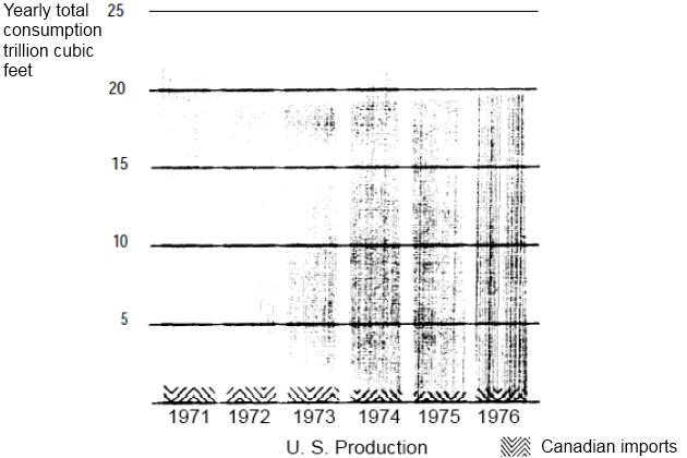
To date, much of this natural gas has been wasted – in 1975, 6,5 trillion cubic feet were vented or flared worldwide.
| Table 1. World proportional natural gas reserves by major supplier country | |
|---|---|
| Country | Percentage |
| USSR | 33 |
| Iran | 14 |
| United States | 10 |
| Algeria* | 10 |
| Abu Dhabi* | 8 |
| Total | 75 |
| Note. Countries with little or no gas demand | |
To use the natural gas which would otherwise be untapped or wasted, importation of natural gas is one of several supplemental supply schemes used by those areas of the world with large energy demand, primarily the:
- United States,
- Europe,
- Japan.
Natural gas has been carried overland by conventional pipelines, and about 1 trillion cubic feet of natural gas is imported in that manner from Canada to the United States each year. However, in order to import natural gas in a form practical for water transportation from Eastern Hemisphere nations, a system has been developed to convert the gas to liquid form at about 1/600th the volume (table 2).
| Table 2. Volume relationships | |||||||||||
|---|---|---|---|---|---|---|---|---|---|---|---|
| LNG conversion factors | Gas | Liquid | Thermal | ||||||||
| Cubic feet | MCF | Pounds | Gallons | Imp. gal. | Cubic feet | Barrels | Cubic meters | Metric tons | Therms | ||
| Gas | 1 MCF | 1 000,0 | – | 46 758 | 12 070 | 10,051 | 1,6134 | 0,28735 | 0,045692 | 0,02123 | 10,860 |
| Liquid | 1 Gallon | 82 850 | 0,082850 | 3,87390 | – | 0,8327 | 0,13367 | 0,02380 | 0,003785 | 0,001759 | 0,89975 |
| 1 Imp, gal | 99 503 | 0,099503 | 4,6526 | 1,201 | – | 0,16054 | 0,02858 | 0,004546 | 0,00211 | 1,08059 | |
| 1 Cubic foot | 619,80 | 0,61980 | 28,981 | 7,4811 | 6,229 | – | 0,17810 | 0,02832 | 0,01316 | 6,7311 | |
| 1 Barrel | 348 008 | 3,48008 | 162,72 | 42,005 | 34,97 | 5,6148 | – | 0,15901 | 0,07388 | 37,794 | |
| 1 Cubic meter | 21,886 | 21,886 | 1 023,3 | 264,16 | 220,0 | 35 314 | 6,2888 | – | 0,46463 | 32 768 | |
| 1 Metric ton | 47,103 | 47 103 | 2 202,4 | 568,53 | 473,4 | 75,996 | 13,535 | 2,1522 | – | 511 54 | |
| Thermal | 1 Therm | 92 081 | 0,09208 | 4,3055 | 1,1114 | 0,92546 | 0,14856 | 0,02646 | 0,00421 | 0,00195 | |
| Note. LNG Gas/Liquid Ratio 619,8 to 1 1086 Btu/Cu. Ft. Spec. Grav. 0,465 | |||||||||||
The liquefied natural gas (LNG) is then shipped in specially constructed tankers, introducing a marine link in the supply and demand of natural gas. This marine link is a large component, consisting of the liquefaction facility at the source of the gas, the LNG tanker, and the receiving terminal and regasification facility at a location near a gas distribution network. It is a very capital-intensive system, which can cost more than $1 billion to construct. A large 500 million cubic feet per day project with four ships could require a $2 billion capital expenditure for liquefaction/export facilities ($1 billion), ships ($150 million each), and import/regasification facilities ($300 million to $400 million). Implementation of all announced LNG projects could require capital expenditures in excess of $35 billion worldwide. In the United States alone, construction of facilities and ships for the import of LNG could require $20 billion.
Such huge capital expenditures are generally financed by a multinational mix of governments and private firms. The US Government has already provided about $716 million in subsidies, loans, and loan guarantees in connection with LNG projects. More than two-thirds of that support has been given to the foreign portions of the projects.
Europe became the first steady market for LNG in 1964 (table 3).
| Table 3. Existing international LNG trade | ||
|---|---|---|
| Date started | Supplier to importer | Amount per day (million cubic feet) |
| 1972 | Brunei to Japan | 737 |
| 1977 | Indonesia to Japan | 550 |
| 1964 | Algeria to France | 400 |
| 1969 | Libya to Italy | 235 |
| 1969 | Libya and Algeria to Spain | 160 |
| 1969 | Alaska to Japan | 135 |
| 1964 | Algeria to United Kingdom | 100 |
| 1971 | Algeria to Boston, Mass. | 44 |
Japan took over as the key market about 1972, receiving about 49 percent of the LNG moving in international trade. However, the United States – which has used very limited imports of LNG only since 1971 – is projected to become a major LNG customer if ventures now planned go forward.
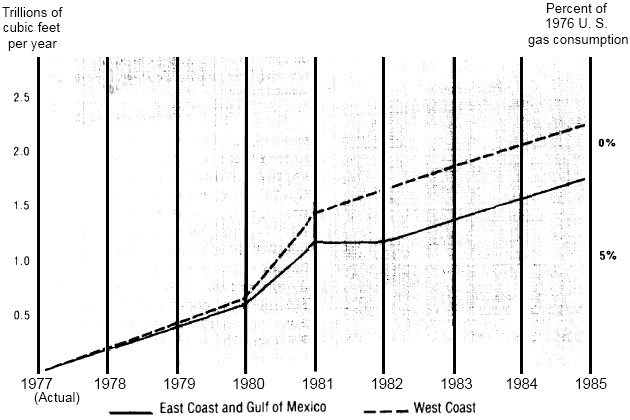
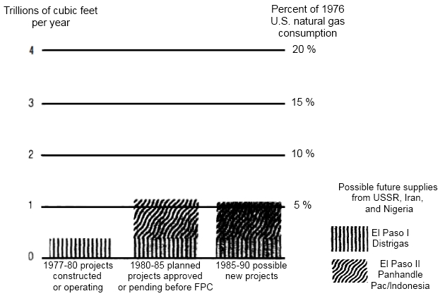
The United States is presently a net exporter of LNG. More than 32 billion cubic feet of natural gas in the form of LNG has been sent to Japan from southern Alaska each year for the past 5 years, while only about 15 billion cubic feet per year is imported from Algeria to Everett, Mass. The LNG imported to Everett is a very small amount, less than one-twentieth of 1 percent of the US consumption of natural gas in 1976. According to industry representatives, however, LNG could be 5 to 15 percent of the total U. S. gas consumption by 1985 (figure 2).
Projects are now proposed which could bring as much as 3,5 trillion cubic feet of LNG per year to the United States from foreign sources within the next 10 to 15 years (table 4).
| Table 4. Status of U. S. LNG import projects | ||||
|---|---|---|---|---|
| Project | Start-up date | Supply source | Status (AGA/FPC) | Quantity (billion cubic feet/year) |
| Existing and firm foreign imports | ||||
| Distrigas I | 1972 | Algeria | Existing/Operational | 1,6 |
| Distrigas IV | 1978 | Algeria | Firm/Pending | 42 |
| El Paso I | 1978 | Algeria | Firm/Approved | 365 |
| Total | 407 | |||
| Probable foreign imports | ||||
| Panhandle Eastern | 1980 | Algeria | Probable/Approved | 179 |
| Pacific Lighting Int | 1980 | Indonesia | Probable/Approved | 197 |
| El Paso II | 1980-82 | Algeria | Probable/Pending | 365 |
| Total | 741 | |||
| Possible foreign imports | ||||
| Tenneco-N B. Canada | 1985 | Algeria | Possible/Filed | 397 |
| Occidental-El Paso | 1985 +/- | USSR | Possible/Not Filed | 365 |
| Brown/Root-Tenneco | 1985 +/- | USSR | Possible/Not Filed | 547 |
| Kalingas | 1985 +/- | Iran | Possible/Not Filed | 285 |
| El Paso-Iran | 1985 +/- | Iran | Possible/Not Filed | 547 |
| Shell-BP | 1985 +/- | Nigeria | Possible/Not Filed | 237 |
| Total | 2 378 | |||
| Grand Total | 3 526 | |||
Ultimately, the supply of natural gas is limited, but since it is currently an underutilized resource in many foreign countries, importing it as LNG could satisfy a significant portion of the US energy demand for at least the next 20 years.
Imports of LNG could be particularly useful in alleviating near-term fuel shortages in certain sectors of the economy or parts of the country. In California, which accounts for 11 percent of US natural gas consumption, LNG could help to alleviate projected energy shortfalls and air quality problems.
If presently planned and approved projects move forward, Algeria would be the major source of the increased imports (figure 3).
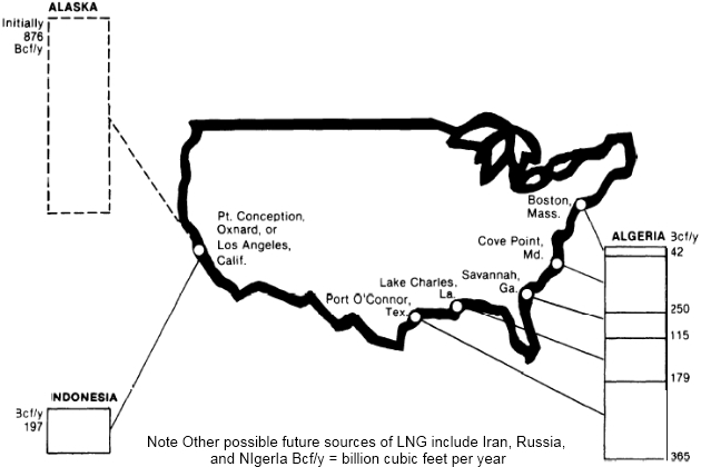
A smaller amount of LNG would come from Indonesia, and there is a possibility of supplies from the USSR, Iran, and Nigeria after 1985. The stability of these foreign supplies and likely results of possible curtailment of LNG shipments to the United States has been identified by this study as one of the potential problems of the LNG system. Foreign supply is discussed further in the critical review section which follows this chapter.
In addition to foreign natural gas, new gas discoveries in Alaska could be transported to the west coast as LNG. This possible supply of gas from the North Slope and southern Alaska could be more than 1 trillion cubic feet a year as early as 1984.
The North Slope is by far the largest of the two Alaskan supplies of natural gas. The method of transportation to be used to bring the North Slope gas to the west coast was to be determined by the President in September? A proposal to transport this gas by pipeline through Canada was being weighed against a proposal to use an LNG system.
Description of LNG
Liquefied natural gas is not the only hazardous cargo transported in the United States today, or is it necessarily the most dangerous. Other cargoes which pose unique hazards when transported in large volumes include:
- liquefied petroleum gas (LPG),
- chlorine,
- acids,
- gasoline.
Liquefied natural gas and LPG are similar in many ways and are treated together as «liquefied gases» by most regulators. Prospects of Liquefied Petroleum Gas Industry and Why it is a Growing MarketLiquefied petroleum gas, however, appears to be better known and accepted by the public. In 1976, 10 million tons of LPG were moving in world trade, most of it going to Japan from the Middle East countries. It is estimated that by 1980, LPG trade will more than double, and that US demand will be as much as 12 million tons. In 1977, there were 441 LPG tankers operating worldwide with a capacity of 3,5 million cubic meters. In comparison, 30 LNG tankers were operating worldwide at the same time with a capacity of 2,2 million cubic meters.
Some unique properties of LNG which affect the design of tankers or terminals are:
- it has an extremely low temperature of -259 °F;
- it weighs about 28 pounds/cubic foot, slightly less than half the weight of water, and would therefore float;
- at normal ambient temperatures, it evaporates very rapidly and expands to about 600 times its liquid volume;
- in the vapor state, and when still very cold, the gas is heavier than air and, in the event of a spill, would hug to the earth’s surface for a period of time until substantially dissipated;
- when the vapor warms up, reaching temperatures of about -100 °F, it is lighter than air and would rise and dissipate in the air;
- in the vapor state, it is not poisonous, but could cause asphyxiation due to the absence of oxygen;
- in the vapor state, concentrations of 5 to 15 percent natural gas are flammable.
Liquefied natural gas is odorless and colorless. It looks much like water. Except for its extremely cold temperature, which requires special handling techniques and materials, the liquid is relatively safe. In bulk form it will not burn or explode. Momentary contact on the skin is harmless although extended contact will cause severe freeze burns, on contact with certain metals such as carbon steel ship decks, LNG can cause immediate cracking.
Note. On September 8, 1977, the President announced that an agreement had been reached with Canada for a pipeline to carry natural gas across that country from Alaska to the west coast of the United States. The Congress has 60 days after formally receiving the President’s plan in which to disapprove the choice if it so desires.
The behavioral patterns of LNG vapor in the atmosphere, however, are not so well understood and may create hazards. If spilled on the ground, LNG would «boil», (vaporize) very rapidly for 2 or 3 minutes until the ground was frozen and no longer emitting heat to the LNG on top of it. This would slow the rate of vaporization and minimize cloud formation dangers.
If spilled on water in a large-scale accident, it is unlikely the water would freeze. Instead the water would continue to warm the floating LNG, vaporizing it and forming a spreading cloud. Researchers currently disagree on the shape, size, movement, and composition of the vapor cloud and the factors which will affect it. It is believed that the concentration of LNG vapor within the cloud is not homogeneous. At the edge of the cloud, where the greatest mixing with ambient air occurs, the concentration of gas is lowest. At the core of the cloud, the concentration is highest. Where the concentration falls within the flammable limits of 5 to 15 percent, the cloud may be ignited and burn back toward the source of the spill. It is generally agreed that, if the vapor from a large LNG spill ignites, it would be beyond the capability of existing firefighting methods to extinguish it. Therefore, the key to reducing the hazard of an LNG fire is a strong prevention program.
The hazards of transporting LNG are somewhat similar to those of LPG, if the two are considered in equal volumes. However, LPG is somewhat more dense than LNG vapor at comparable temperatures. In the event of a spill of either liquid on water, the liquid would rapidly spread by gravity until a large vapor cloud would form. LNG would vaporize considerably faster than LPG because LNG is more volatile. Thus, the LPG vapor cloud would evolve over a longer period of time, and would be more cohesive than the LNG cloud. LPG has the greatest potential for detonation both in open air and confined. LPG stored in tanks continually heated by a surrounding flame causes a rise in pressure which leads to detonation. Open-air detonations of LPG have been demonstrated by experiment whereas the same is not true of LNG.
Research into the behavior of spilled LNG and an LNG cloud is another critical area discussed in the next chapter.
Safety record of early use of LNG
Liquefaction of natural gas is achieved by cooling the gas to -259 °F. The process was developed on a large scale during the first quarter of the 20th century to simplify the transportation and storage of natural gas, since the liquid state is 1/600th the volume of the gaseous state.
Until recently, LNG was utilized primarily in operations which produced the liquid and stored it for use only during peak demand, for example, in cold winter weather. There are 89 of these facilities operating in the United States today to produce and/or store domestic LNG. Known as «peak shaving plants», they have a combined storage capacity of 2 million cubic meters. In addition, one plant in Boston imports and stores foreign LNG. Its capacity is 146 000 cubic meters. The peak shaving plants have existed safely for years, without much public attention to either their location in heavily populated areas or their operations. Only one major incident has marred the safety record of these plants.
That accident occurred at the first LNG installation in 1944. At that time, a storage tank owned by East Ohio Gas Company in Cleveland ruptured, spilling 6 200 cubic meters of LNG into adjacent streets and sewers. The liquid evaporated, the gas ignited and, where confined, exploded. The disaster remains the most serious LNG accident anywhere in the world. It resulted in 128 deaths, 300 injuries, and approximately $7 million in property damage.
Based on investigations made by the US Bureau of Mines after the accident, it was generally agreed that the tank failed because it was constructed of 3,5 percent nickel steel, which becomes brittle on contact with the extreme cold of LNG. Since the Cleveland disaster, it has become standard practice in the LNG industry to use 9 percent nickel steel, aluminum, or concrete and to surround storage facilities with dikes capable of containing the contents of the tank if a rupture occurs.
The only other significant accident related to LNG to date occurred at a Staten Island import facility in 1973; where 40 workmen repairing an empty LNG tank were killed when the roof of the tank collapsed as a result of a fire.
While the Staten Island tank disaster precipitated active local opposition to LNG, the gas industry has repeatedly argued that the accident was not due to any characteristic or handling of LNG, but was an industrial accident involving an insulation fire. However, a Bureau of Mines study of the accident indicated that there was enough LNG in the insulation that it could have been released very quickly into the tank once ignition had started.
The only other accident in the United States mentioned in connection with LNG took four lives in Oregon. This accident, however, took place during construction of the storage tank before LNG had ever been introduced into the facility.
Over the past 10 to 20 years, the peak shaving facilities have been engaged in all phases of LNG handlings:
- liquefaction,
- regasification,
- loading and unloading,
- storage,
and shipment by:
- pipeline,
- truck,
- rail,
- barge.
However, new LNG projects involve much larger scale facilities entirely dependent on marine shipment, and these are the focus of this study.
Regulation of import projects
Before any LNG import or export project can begin operation, more than 130 permits must be obtained from Federal, State, and local agencies (table 5), and 12 different Federal agencies are involved in approvals and controls.
| Table 5. Cove Point, Md., Permits | |||
|---|---|---|---|
| Regulatory agency | Description of action | Application date | Permit date |
| Terminal | |||
| Board of County Commissioners of Calvert County, Md | Rezoning 317 722 acres from Al to Il | – | 08.11.70 |
| Federal Power Commission | Opinion No. 622 CP71-68 | 09.21.70 | 06.28.72 |
| Federal Power Commission | Opinion No. 622A CP71-289 | 06.04.71 | 10.05.72 |
| Federal Power Commission | Amended – Tunnel plan | 12.08.72 | 03.30.73 |
| Calvert County Department of Inspection and Permits | Site grading for office building | 06.09.72 | 06.14.72 |
| Calvert County Health Department | Deep-drilled well and sewagedisposal system | 06.19.72 | 07.13.72 |
| Completion certificate | 11.15.72 | ||
| Calvert County Department of Inspection and Permits | Construction of office and maintenance building | 06.22.72 | 07.21.72 |
| Department of the Army, Baltimore | Construction of pier | 09.01.72 | |
| District, Corps of Engineers | 04.07.71 | 08.31.72 | |
| State of Maryland, Department of Natural Resources | Water quality certification | – | 12.18.72 |
| State of Maryland, Department of Natural Resources | Wetlands license | 12.04.72 | 12.26.72 |
| Department of the Army, Baltimore District, Corps of Engineers | Construct unloading terminal and tunnel and dredge in Chesapeake Bay | 12.04.72 | 12.29.72 |
| State of Maryland, Department of Natural Resources | Appropriate and use ground water for sanitary facilities | 10.21.72 | 11.28.72 |
| State of Maryland, Department of Natural Resources | Construction of two entrances | 11.20.72 | 03.12.73 |
| Extension | 07.05.73 | ||
| Calvert Soil Conservation District | Erosion and sediment control measures | 04.05.73 | 05.14.73 |
| Calvert County Department of Inspection and Permits | Site grade and preparation for construction; LNG terminal process area | 04.05.73 | 05.18.73 |
| Calvert County Department of Inspections and Permits | Construction of cofferdam | 08.14.73 | 08.15.73 |
| State of Maryland Fire Marshal | Approval of office and warehouse | 08.31.73 | |
| State of Maryland, Department of Forests and Parks | Burning debris | 09.17.73 | |
| State of Maryland, Department of Natural Resources | Small pond permit | 10.01.73 | |
| Calvert County Department of Inspections and Permits | Site grading in lowland area | 10.12.73 | 10.12.73 |
| Calvert County Department of Inspections and Permits | Construction of LNG storage tanks | 10.15.73 | 10.24.73 |
| State of Maryland Comptroller of the Treasury | Sales and use tax direct payment permit | 01.02.74 | |
| Calvert County Health Department | Construction of deep drilled well and sewage disposal system | 10.25.73 | 01.29.74 |
| Completion certificate | 02.24.75 | ||
| Calvert County Health Department | Construction of deep drilled well and sewage disposal system | 10.25.73 | 01.29.74 |
| Completion certificate | 01.07.75 | ||
| State of Maryland, Water Resources Administration | Appropriate and use water for sanitary facilities, cooling water, testing and fire protection | 01.31.74 | |
| Federal Communications Commission | Radio license | 04.15.74 | |
| State of Maryland Fire Marshal | Approval of fire protection plan | 05.30.74 | |
| Department of Transportation, U. S. Coast Guard | Private aids to navigation (five lighted survey towers) | 07.05.74 | 07.18.74 |
| State of Maryland Fire Marshal | Approval of use of tunnel by personnel | 08.26.74 | |
| Calvert County Department of inspections and Permits | Construction of two firewater storage tanks | 09.18.74 | 09.20.74 |
| Calvert County Department of inspections and Permits | Construction of 12 buildings for use with receiving terminal | 10.12.74 | 10.23.74 |
| State of Maryland Environmental Health Administration | Construction of emergency vent heater | 07.11.75 | 09.16.75 |
| State of Maryland Environmental Health Administration | Construction of LNG vaporizer | 07.11.75 | 09.16.75 |
| State of Maryland Environmental Health Administration | Construction of emergency purge nitrogen vaporizer | 07.11.75 | 09.17.75 |
| State of Maryland Environmental Health Administration | Construction of firewater tank heater | 07.11.75 | 09.17.75 |
| State of Maryland Environmental Health Administration | Construction of gas turbine fuel gas heater | 07.11.75 | 09.17.75 |
| State of Maryland Environmental Health Administration | Construction of boil-off gas reheater | 07.11.75 | 09.17.75 |
| State of Maryland Environmental Health Administration | Construction of gas turbine generator | 07.11.75 | 09.17.75 |
| Calvert County Department of Electrical Inspections | Electrical permit for onshore ventilation building | 09.05.75 | |
| Calvert County Department of Inspections and Permits | Construction of seven offshore buildings | 01.23.76 | 02.03.76 |
| State of Maryland Fire Marshal | Review of electrical area classifications | 06.04.76 | |
| Calvert County Fire and Rescue Commission | Inspection of fire apparatus | 08.03.76 | |
| Calvert County Department of Inspections and Permits | Site grade for warehouse | 08.11.76 | |
| Calvert County Department of Inspections and Permits | Construction of warehouse | 08.11.76 | |
| Calvert County Department of Inspections and Permits | Construction of sign at terminal entrance | 08.27.76 | 08.31.76 |
| United States Department of the Interior | Seagull depredation permit. | 11.09.76 | |
| United States Coast Guard | Approval of survival capsules | 06.17.76 | |
| State of Maryland, Department of Licensing and Regulation | License and regulation certificate for offshore elevator | 01.07.77 | |
| United States Coast Guard | Certificate of Inspection for Miss Methane | 09.30.76 | |
| United States Coast Guard | License of vessel under 20 tons for Miss Methane | 01.31.77 | |
| State of Maryland, Water Resources Administration | Oil operations permit | 03.31.77 | 05.05.77 |
The Federal Power Commission (FPC), the Coast Guard, and the Office of Pipeline Safety Operations (OPSO), are the agencies most involved in LNG and are discussed in appropriate sections of this chapter (table 6).
| Table 6. Cove Point, Md., Permits | |||
|---|---|---|---|
| Regulatory agency | Description of action | Application date | Permit date |
| Pipeline | |||
| Maryland Board of Public Works – Department of Natural Resources | Wetland license | 4.01.74 | 09.19.74 |
| 04.25.75 | |||
| Maryland Department of Natural Resources | Construction in a waterway | 04.01.74 | 04.23.75 |
| Corps of Engineers | Construction of five 36-inch pipeline submarine crossings | 04.10.74 | 04.15.75 |
| Amended | 03.07.75 | 12.31.75 | |
| Maryland Department of Natural Resources | Water Quality Certification five pipeline crossings | 08.22.74 | |
| Revised | 09.10.74 | ||
| Virginia Marine Resources Commission | Dredge and backfill a trench for pipeline crossing of Potomac River | 03.07.75 | 08.27.74 |
| Revised | 03.25.75 | ||
| Viginia State Water Control Board | Dredge and backfill a trench for pipeline crossing Potomac River | 07.15.74 | 09.26.74 |
| Amended | 03.07.75 | 04.03.75 | |
| Virginia Department of Taxation | Sales and use tax direct payment permit | 03.01.75 | |
| Federal Power Commission | Amended route | 04.10.75 | |
| Change construction dates | 08.01.75 | ||
| Commonwealth of Virginia Department of Highways and Transportation (Fairfax County) | Permit for temporary entrance to right-of-way № 754738 | August 1975 | |
| Commonwealth of Virginia Department of Highways and Transportation (Fairfax County) | Permit for temporary entrance to right-of-way № 754826 | August 1975 | |
| Commonwealth of Virginia Department of Highways and Transportation (Fairfax County) | Permit for temporary entrance to right-of-way № 754513 | July 1976 | |
| Commonwealth of Virginia Department of Highways and Transportation (Fairfax County) | Permit for temporary entrance to right-of-way № 754950 | October 1975 | |
| Commonwealth of Virginia Department of Highways and Transportation (Fairfax County) | Permit for temporary entrance to right-of-way № 755740 | 11.07.75 | 11.19.75 |
| Commonwealth of Virginia Department of Highways and Transportation (Fairfax County) | Permit for temporary entrance to right-of-way № 755739 | 11.07.75 | 11.19.75 |
| Commonwealth of Virginia Department of Highways and Transportation (Fairfax County) | Permit for temporary entrance to right-of-way № 75511 | October 1975 | |
| Commonwealth of Virginia Department of Highways and Transportation (Fairfax County) | Permit for temporary entrance to right-of-way № 755008 | September 1975 | |
| Commonwealth of Virginia Department of Highways and Transportation (Fairfax County) | Permit for temporary entrance to right-of-way № 755734 | 10.31.75 | December 1975 |
| Commonwealth of Virginia Department of Highways and Transportation (Loudoun County) | Permit for temporary entrance to right-of-way № 756041 | 12.09.75 | 12.17.75 |
| Commonwealth of Virginia Department of Highways and Transportation (Loudoun County) | Permit for temporary entrance to right-of-way № 756040 | 12.09.75 | 12.17.75 |
| Board of County Commissioners of Charles County, Md. | Grading permit, pipeline rightof- way | 10.21.74 | 10.24.74 |
| Washington Suburban Sanitary Commission-Prince Georges County | Sediment Control Permit, pipeline right-of-way | 07.16.74 | |
| 09.16.74 | |||
| State of Maryland-Maryland Forest Service, Department of Natural Resources | Roadside tree permit (Calvert, Charles and Prince Georges Counties) | 07.14.75 | 07.22.75 |
| Department of Inspections and Permits, Calvert County, Md. | Zoning approval, pipeline right-of-way | 06.17.75 | 06.18.75 |
| 06.23.75 | |||
| Department of Inspections and Permits, Calvert County, Md. | Grading permit, pipeline rightof- way | 06.07.74 | 10.11.74 |
| 06.13.75 | |||
| Department of Inspections and Permits, Calvert County, Md. | Grading permit, access road to right-of-way Cove Point | 07.24.74 | 07.24.75 |
| Department of Inspections and Permits, Calvert County, Md. | Use and occupancy permit | 02.17.75 | 02.18.75 |
| Department of Public Works, Prince Georges County, Md. | Construction within public right-of-way (three road crossings) | 06.10.75 | 08.04.75 |
| Department of Transportation, State of Maryland (Calvert County) | Pipeline road crossing № 5-C10943-75 | May 1975 | |
| Department of Transportation, State of Maryland (Calvert County) | Pipeline road crossing № 5-C-1088O-75 | April 1975 | |
| Department of Transportation, State of Maryland (Calvert County) | Road crossing (cable) № 50C-11046-75 | August 1975 | |
| Department of Transportation, State July 1975 of Maryland (Charles County) | Pipeline road crossing № 5-CH-10881-75 | July 1975 | |
| Department of Transportation, State of Maryland (Charles County) | Pipeline road crossing № 5-CH-10942-75 | May 1975 | |
| Washington Suburban Sanitary Commission (Prince Georges County, Md.) | Pipeline road crossing № 17090, 3-pg. 208-75 | May 1975 | |
| Washington Suburban Sanitary Commission (Prince Georges County, Md.) | Pipeline road crossing № 17094, 3-pg. 282-75 | June 1975 | |
| Washington Suburban Sanitary Commission (Prince Georges County, Md.) | Pipeline road crossing № 17089 | May 1975 | |
| United States of America, U. S. Navy Railroad (Maryland) | Pipeline railroad crossing № NF(R)26225 | 07.21.75 | |
| Calvert Soil Conservation District | Sediment and erosion control for Calvert County, Md. | 06.07.74 | 03.12.75 |
| Charles Soil Conservation District | Sediment and erosion control for Charles County, Md. | 09.25.74 | 10.24.74 |
| County of Fairfax, Va. | Sediment and erosion control for Fairfax County | 11.07.74 | 02.13.75 |
| 08.22.75 | |||
| 09.05.75 | |||
| County of Fairfax, Va. | Occupancy permit | September 1975 | September 1975 |
| County of Fairfax, Va. | Site plan waiver for pipeline construction | 03.31.75 | |
| 09.10.75 | |||
| Department of Environmental Management, Fairfax County, Va. | Pipeline road crossing № 1043O | 02.17.76 | |
| Zoning Administrator, Loudoun County, Va. | Zoning permit for measuring station at Loudoun | 04.08.76 | 04.08.76 |
| Department of Engineering and Inspections, Loudoun County, Va. | Building permit for instrument and transducer buildings at Loudoun | 04.14.76 | 06.01.76 |
| Department of Engineering and Inspections, Loudoun County, Va. | Electrical permit for instrument and transducer buildings at Loudoun | 07.08.76 | 07.08.76 |
| Health Department, Loudoun County, Va. | Permit to install sewage disposal system and water well | 04.14.76 | 05.24.76 |
| Maryland Board of Public Works | Wetlands license | 09.19.74 | |
| Fairfax Planning Commission | Construction approval for modified route per settlement agreement | 02.13.75 | |
| Fairfax County Board of Supervisors | Final approval given modified route | 03.31.75 | |
| Fairfax Board of Zoning | Zoning approval given modified route | 03.10.75 | |
| Charles County | Pipeline construction report filed | 05.15.75 | |
| Calvert County | Pipeline construction report filed | 06.30.75 | |
| Fairfax County | Sediment and erosion control plan approved | 08.22.75 | |
| State of Maryland | License to cross Calvert Cliffs State Park | 09.29.75 | |
| Prince Georges County | Special ordinance authorizing pipeline construction | 11.24.75 | |
| Loudoun County | Sediment and erosion control plan filed-permit not required | 01.23.76 | |
| Loudoun County Planning Commission | Pipeline route approved | 01.26.76 | |
| Maryland Department of Natural Resources | Surface water appropriation for hydrostatic test | 03.29.76 | |
| Maryland Department of Natural Resources | Permit for discharge of test water | 03.29.76 | |
Other participating Federal Agencies in LNG import projects:
- Council on Environmental Quality. The FPC submits preliminary and final environmental impact statements to CEQ for review.
- Department of Defense. DOD is consulted by the FPC for views on national security implications of each LNG import application.
- Department of the Interior. Permits are required if construction or operation of a terminal affects wildlife in the area.
- Department of State. State is consulted by the FPC for views on national security implications of each LNG import application.
- Environmental Protection Agency. Permit is required from EPA if there are any discharges into the ocean adjacent to an LNG terminal.
- Export-Import Bank. Provides loans to foreign governments to support purchases of U. S. goods and services in the construction of liquefaction and related LNG facilities.
- Federal Communications Commission. Licenses are required for radio operations.
- Federal Power Commission. The FPC regulates importation and the interstate transportation and sale of natural gas.
- Office of Pipeline Safety Operations. OPSO establishes and enforces minimum Federal safety standards for all pipelines in or affecting interstate or foreign commerce.
- U. S. Army Corps of Engineers. Permit is required for any dredging activity and construction of any object in the navigable waters of the United States.
- U. S. Coast Guard. The Coast Guard is responsible for the safety of the marine link of LNG import operations, by certification of LNG ships to ensure that minimum design and construction standards, and the establishment of operating procedures for bringing LNG into U. S. ports.
- U. S. Maritime Administration. MARAD provides a variety of financial aids for the construction and operation of U. S. flag LNG tankers.
The most crucial agency in this milieu is the Federal Power Commission, which under the Natural Gas Act of 1938, has power to approve or reject any proposed project in three ways:
- it must determine whether of not the public interest will be served by LNG importation;
- it must authorize construction or extension of any facilities to be used in the transportation or sale of interstate natural gas;
- it has the authority to establish the price at which the gas is sold.
The Federal Power Commission has broad discretionary powers in determining what is and what is not in the public interest and in stipulating conditions which must be met in order to meet the public interest.
To date, the FPC has been asked to rule on one LNG export project and 10 LNG import projects (see table 4). The export project, with liquefaction facilities in Kenai, Alaska, has been approved and is operating. Of the import projects, three have received final approval; one has received initial approval, subject to review. One import project with its terminal and regasification plant in Everett, Mass., is in operation. Another, with import facilities in Cove Point, Md., and Savannah, Ga., is scheduled to begin operation later this year. Facilities for the approved project at Lake Charles, La., have not yet been constructed, nor have facilities for the Oxnard, Calif., terminal which has received only initial approval.
The FPC approves the import projects by means of an express order authorizing importation and certificates of public convenience and necessity (authorization and stipulations for construction and operation of facilities). The approvals are obtained by means of a complicated quasi-judicial procedure which routinely takes several years from the time an application is filed until it is approved. First, an evidentiary hearing is held before an administrative law judge, in which the applicant, staff, and interveners each present their views of the nature of the project, cost estimates, the need for additional supply of gas, and Environmental Impact of Liquefied Natural Gasenvironmental consequences of the project. The evidence presented also includes an environmental impact statement prepared by the FPC, an engineering and safety review by the cryogenics division of the National Bureau of Standards, and a risk analysis by the FPC staff. On the basis of this evidence, the FPC administrative law judge makes an initial decision.
Second, there is a period of review during which any of the parties may file exceptions to the decision. At the end of the review period, the commissioners make a final decision which may uphold the initial decision or change it completely. The final decision is subject to an appeal in one of the US Courts of Appeal.
Since the historic role of FPC has been to regulate the entry of suppliers into the interstate natural gas market and to ensure that interstate sales of gas take place at prices that are «just and reasonable», the agency has limited its activities to licensing and ratemaking. There is little onsite inspection to assure compliance with stipulations contained in the licenses. The exception to this general rule occurs when a company wishes to expand existing facilities and submits a new application. In that context, FPC engineers inspect the facility to judge its operating performance. A critical analysis of the decisionmaking process which leads to certification of LNG projects and the difficulties of pricing policies are discussed in the next chapter.
LNG tanker technology
Liquefied natural gas import projects involve a complex consortia of energy and transportation companies. The gas supplier is usually represented by a foreign government or State-owned subsidiary company. The recipient of the gas at the import terminal is generally a consortia of gas utilities and/or pipeline companies, which use the gas in their own systems and sell to other distribution or utility companies. The supplier and receiver are connected by a transportation company, the subsidiary of an oil, gas, or pipeline company, which owns and operates the LNG tankers.
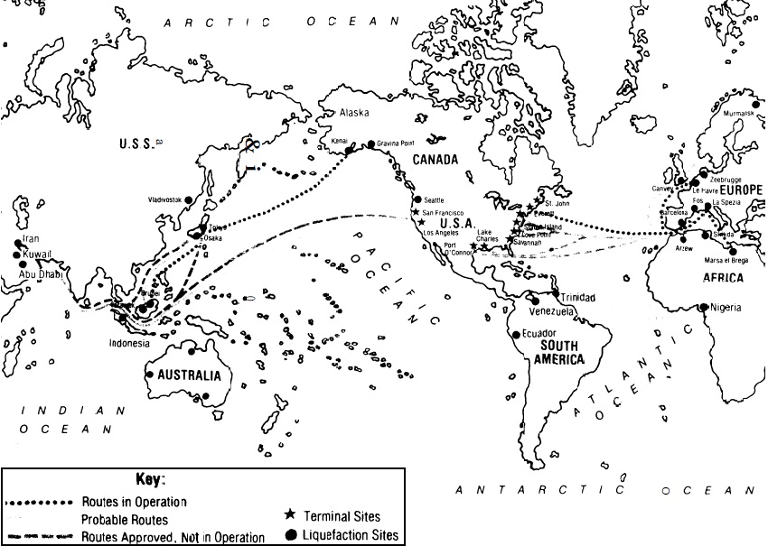
Liquefied natural gas tanker technology has been developed over the past 20 years to the point where, currently, about a dozen worldwide trade routes are either in operation, planned, or proposed for LNG shipping (figure 4).
Growth in the world LNG fleet has been rapid (figure 5).
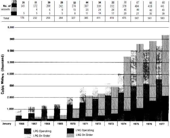
Seventy-two ships will be operational by 1980, with a possibility that 33 more would be required if all planned LNG projects go through.
Currently, only one LNG tanker is engaged in regular import trade with the United States, that is the French ship, the Descartes, which has brought 25 shipments from Algeria to the Distrigas peak shaving plant in Boston since July 1975. Nine more LNG tankers will join the US trade early next year when import terminals under construction at Cove Point, Md., and Savannah, Ga., begin operation, and five more when an import terminal at Lake Charles, La., is online about 1980 (table 7).
| Table 7. LNG tankers on order or under constructionin U. S. shipyards | |||
|---|---|---|---|
| Shipyard | No. of vessels | Containment system design | |
| Avondale | 3 | Conch | Self-supporting aluminum alloy prismatlc tanks, British design |
| General Dynamics | 10 | Kvaerner-Moss | Spherical aluminum alloy tank, Norwegian design |
| Newport News | 3 | Technigaz | Stainless steel alloy membrane French design |
| Sun Shipbuilding | 2 | MacDonald Douglas/ Gas Transport | Invar (nickel-steel), American/ French design |
If other projects now proposed are approved, it is possible that 12 additional LNG tankers will be required for imports to the United States and 14 for shipments from Alaska to the continental United States. By 1985, a total of 41 tankers could be calling at continental US ports. (In addition, two tankers are involved in export of LNG from Alaska to Japan through 1985).
What is liquefied natural gas tankers?
Liquefied natural gas tankers are bulk cargo ships which require unique design and materials to handle the very low-temperature gas.
Most LNG tankers range in size from about 40 000 cubic meters to planned ships of 165 000 cubic meters (figure 6).
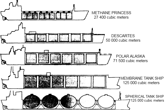
The industry standard has become the 125 000 to 130 000 cubic meter ship. Each ship this size carries enough LNG to heat a city of 100 000 population for 1 month.
By comparison to the better known crude oil tankers, the largest LNG ships are one-half to one-fourth the total size of the very large crude carriers (VLCC or «supertanker») (table 8), some of which are more than 400 000 deadweight tons.
A comparison of the principal dimensionsa, cargo deadweightb, and full-load dlsplacementc of a 125 000 cubic meter LNG ship and a variety of crude oil tankers.
| Table 8. Comparison of LNG tanker and crude oil tankers | ||||||
|---|---|---|---|---|---|---|
| 80 000 dwt oil tanker | 100 000 dwt oil tanker | 137 000 dwt oil tanker | 125 000 cu/m LNG ship | 476 000 dwt oil tanker | 554 000 dwt oil tanker | |
| Length | 811 | 848 | 974 | 936 | 1 243 | 1 359 |
| Breadth | 125 | 128 | 134 | 144 | 203 | 207 |
| Depth | 57 | 65 | 85 | 82 | 118 | 118 |
| Draft | 44 | 50 | 54 | 36 | 93 | 94 |
| Dwt | 80 459 | 100 300 | 137 010 | 63 100 | 476 025 | 553 700 |
| Full-load displacement | 105 000 | 128 500 | 172 500 | 94 500 | 509 000 | 631 000 |
A 130 000 cubic meter LNG tanker with a 143-foot beam and a 900- to 1 000-foot length is roughly equivalent to a 100 000-deadweight ton oil tanker.
The LNG tanker is a shallow draft vessel, about 36 feet, on which the cargo-carrying capacity is increased by adding to the length instead of the depth. It has an unusually large amount of freeboard, rising about 50 feet out of the water. Because of its visible length and height, the LNG tanker appears larger than some VLCCs.
The LNG tanker is a high-powered, highspeed ship, with an optimum service speed in the 20 knot range, about 5 knots faster than most oil tankers.
New LNG tankers are fueled by their own cargoes. Immediately upon being loaded in the tanker, LNG begins to evaporate and continues to do so throughout the entire voyage. In a typical design, the vapor produced during the voyage is used as the ship’s fuel and may be sufficient to meet 100 percent of the fuel requirements. However, safety regulations require that the ship carry, and be equipped to use, fuel oil as well. After the ship is unloaded, a small percentage of the LNG cargo is retained in the tanks for cooling purposes and this supplies part of the fuel requirements for the return trip.
The tankers are equipped with specialized systems for handling LNG and for combating potential hazards associated with liquid spillage and fire. These include:
- high-expansion foam and dry powder fire protection systems;
- water-spray systems for flooding deck piping;
- pressure-, temperature-, and leak-monitoring systems.
Cargo handling systems are provided for loading and discharging LNG, for cooling down and warming up tanks, for transmittal of boil-off gas to the ship boilers and, most importantly, to provide inert atmospheres in the spaces surrounding the Gas Freeing of Cargo Tanks on Liquefied Natural Gas Carrierscargo tanks and in the tanks themselves prior to and after aeration at the time of drydocking.
Each LNG tanker is a complicated vessel, representing approximately a $100- to $150-million investment. Most US flag LNG tankers are financed with a variety of aids from the Maritime Administration, including construction differential subsidies, operating differential subsidies, and ship mortgage guarantees.
To date, the Maritime Administration has authorized approximately $270,3 million for subsidy of all LNG tankers. (Federal financial aids are also provided by the Export-Import Bank, although that aid is made available to foreign governments in order to promote the use of US goods and services in their projects. To date, the Export-Import Bank has provided approximately $483 million in loans and loan guarantees to Algeria to support construction of liquefaction plants and related facilities).
The construction cost of an LNG tanker is roughly twice that of an oil tanker of similar size. Most of the increased cost for LNG tankers is due to special design features of the containment system which holds the low-temperature, low-density cargo.
The standard 125 000 cubic meter LNG tanker usually has five cargo tanks, each with a capacity of about 25 000 cubic meters (figure 7).
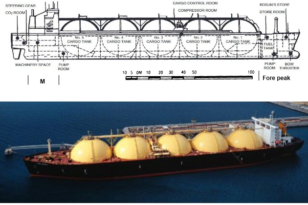
Liquefied natural gas tankers constructed by General Dynamics use five spherical tanks of about 25 000 cubic meters each Tanks for the ships are constructed in South Carolina and towed by barge to the shipyard at Ouincy, Mass, where they are mounted into the ship hull.
An eight-story building could fit inside each of these large cargo tanks, which function in the same way as the common Thermos bottle. A cold product – LNG – is introduced into the container and the insulation surrounding the tank (comparable to the vacuum jacket in the Thermos bottle) is the sole means by which the cargo is kept cold. No refrigeration is employed on the LNG carrier.
From the 15 or more cargo tank system designs, two basic types have become most common: the freestanding tank and the membrane tank.
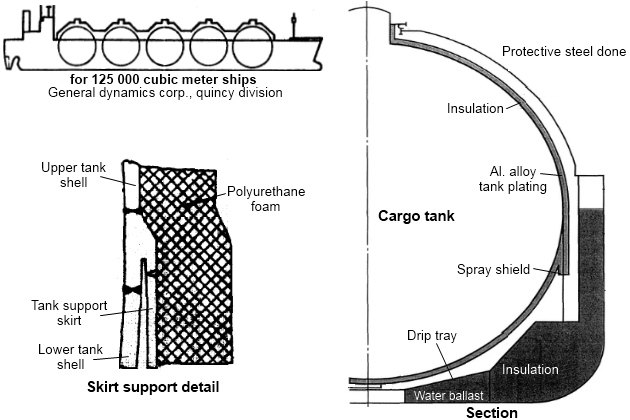
The freestanding tanks are self-contained, usually spherical or prismatic in shape, made of aluminum alloy or 9 percent nickel steel with layers of insulation on the outside (figures 8 and 9).
The tanks are welded to cylindrical skirts or otherwise tied to supporters which are welded to the ship structure.
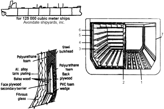
1 – balsa/plywood support panels; 2 – canter-line keyway support panels; 3 – free-standing aluminum tank; 4 – fiberglass bat; 5 – polyurethane foam; 6 – nitrogen inerted space; 7 – inner hull of ship
With the membrane design (figure 10), the ship’s hull, in effect, becomes the outer tank.
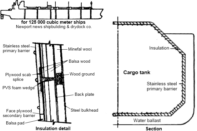
Insulation is installed thereon, and a membrane placed on the inside to retain the liquid. The inner surface of this «double hull» is either high nickel steel or stainless steel.
The unique design problems associated with LNG tankers stem primarily from the need to contain and insulate the extremely cold LNG cargo and from the fact that many materials such as mild steel will become brittle and fail at very low temperatures. Special materials used for the interior of cargo tanks must be able to withstand both the very low temperatures when filled with LNG and the normal temperatures when empty. When metals are subject to these temperature changes of as much as 300 degrees, they expand and contract and, in the case of freestanding tanks, the whole structure of the tank interior must be able to move within the ship. In addition, up to 2 feet of very efficient insulation is necessary around each tank in order to minimize heat leak into the tank during the voyage from liquefaction plant to receiving terminal and back.
So far, none of the containment systems in use has been established as clearly superior to the others (table 9), and it is too early in the history of LNG carriers to have determined meaningful life-cycle cost comparisons.
| Table 9. Comparative characteristics of some LNG tank systems | ||||
|---|---|---|---|---|
| Characteristics | Free standing tanks | Membrane tanks | ||
| Prismatic | Spherical | |||
| 1 | System designs | Conch | Kvaerner-Moss | Gaz transport |
| Esso | Technigaz | Gazocean | ||
| McMullen | Gaz transport (Cylindrical) | |||
| A. G. Weser | Sener | I. H. I. (semi-membrane) | ||
| Hitachi/Esso | Bridgestone (semi-membrane) | |||
| 2 | Safety in event of vessel grounding/collision or other emergency | Compared with membrane system less likelihood of hull damage being transmitted to cargo tanks. More efficient use of cubic spase. | Safest system in event of grounding or collision – tank structure independent of hull and most void space between vessel hull and cargo tanks. Spherical tanks can be pressurized for emergency discharge in case of cargo pump failure. | Damage to hull of vessel may be more easily transmitted to tank structure that with free-standing tanks. Membrane systems are also more liable to damage or puncture due to causes such as: a. surging of cargo in tank; b. entry of tank for inspection or repair. |
| 3 | Reliability of containment system | Most ship years operating experience and most experience without primary barrier failure. Structure can be analyzed and risk of fatigue failures minimized. Tanks can be constructed and 100 % inspected prior to installation in vessel. | Tank system easiest to analyze structurally: therefore can be made most reliable. | Stucture cannot easily be analyzed and therefore difficult to assure absence of fatigue failures. This could potentially lead to costly offhire and repair time over the project life. |
However, each of the present systems is based on many years of design and testing, and research is continuing into new containment systems using materials such as concrete and glass-reinforced plastic.
Safety analyses conducted for LNG projects have constantly identified a ship accident as the most likely event that could trigger the most serious type of LNG accident. A ship collision could result in the rupture of one or more cargo tanks and spill a large amount of LNG onto the water. A water spill would spread much farther and evaporate much more quickly than a land spill. While it is most likely that a collision would produce some source of ignition which could fire the LNG vapor around the ship, a huge vapor cloud could be generated if no ignition occurred.
A critique of LNG tanker design and construction is included in the next chapter.
LNG tanker certification and regulation
The Coast Guard has primary responsiblity for the safe construction and operation of the LNG tankers and activities in ports where the tankers call.
Under the Ports and Waterways Safety Act of 1972 and the Dangerous Cargo Act of 1970, the Coast Guard is required to establish and enforce design and construction standards for US flag LNG tankers and foreign flag Gas analysis of LNG on tankersLNG tankers entering the 3-mile territorial waters of this country. It does so by letters of compliance for foreign vessels and certificates of inspection for U. S. vessels.
The criteria used for both are essentially the same, however, Federal regulations which are specifically applied to US flag ships are simply used as guidelines for foreign ships.
The Letter of Compliance program which is now in operation requires that the Coast Guard review the vessel with respect to cargo containment, cargo safety, and the safety of life and property in US ports. Features covered by the review include:
- design and arrangement of cargo tanks and cargo piping and vent systems;
- arrangement and adequacy of installed fire extinguishing system and equipment;
- safety devices and related systems which check the cargo and surrounding spaces to give warning of leaks or other disorders which could result in a casualty;
- isolation of toxic cargoes;
- compatibility of one cargo with another and with the materials of the containment system;
- suitability of electrical equipment installed in hazardous areas.
The review is accomplished by inspection of detailed plans and specifications submitted in writing by the vessel owner, inspection of documentation that the vessel is accepted by a recognized foreign classification society whose standards provide the same degree of safety as comparable US standards, and inspection of the ship itself on its first visit to a U. S. port. Coast Guard boarding parties examine the:
- vessel’s arrangement and cargo systems;
- tanks;
- piping;
- machinery;
- alarms.
They also observe the condition of the vessel, vessel operation, cargo handling operations, firefighting capability, and personnel performance. Serious problems, such as any involving inoperative safety equipment, leaking cargo piping, or nonexplosion-proof electrical installations, may require immediate correction. Minor problems may require correction prior to a return trip to the United States.
If the vessel meets all applicable requirements, a Letter of Compliance will be issued and the vessel must continue to meet the standards of the first visit on all subsequent calls at US ports. To assure continued compliance, the Coast Guard makes a less extensive examination of the vessel each time it enters U. S. ports.
The Coast Guard requirements for the design, construction, and testing of US flag vessels are contained in 46 CFR 38. New regulations are being drawn up but are not yet complete. The Coast Guard has also proposed regulations which would set minimum standards for persons employed on U. S. flag LNG ships and is working with international groups to develop standards for foreign crews. The regulations now in effect cover:
- ship stability and survivability;
- ship hull materials;
- gas dangerous areas;
- electrical arrangements;
- firefighting arrangements;
- ventilation;
- cargo containment systems;
- temperature and pressure control;
- instrumentation of the ship.
They also cover systems relating to the:
- transfer of LNG, such as the means of loading and offloading the cargo;
- piping materials;
- piping insulation;
- valving;
- instrumentation, construction, and testing of the systems.
Inspections for compliance with these standards are carried out during construction of the vessels. In general, requirements result in the design of ships which the Coast Guard believes to meet a consistent and reasonable level of safety and provide for means of dealing with casualties such as tank overfilling, overpressuring, and emergency shutdowns. In general, the vessels are designed to Survive two-compartment flooding from collision or stranding with reserve stability. They are not designed to withstand a major collision or stranding without cargo release, but the design does limit the release to the tanks directly involved in an incident.
In addition to minimizing the possibility of collisions, strandings, or other incidents, the Coast Guard has specified operational controls on the vessels while entering, moored, or leaving a US port. By regulations promulgated under 50 USC 191, Executive Order 10173, and the Ports and Waterways Safety Act of 1972, the Coast Guard Captain of the Port has control over any vessel within the territorial sea and may prescribe conditions and restrictions for the operation of waterfront facilities. Under the regulations, the Captain of the Port in Boston has drawn up an Operations/Emergency Plan for LNG shipments coming into the Everett, Mass., LNG facility. Similar plans will be drawn up for all LNG import terminals. The plan takes into account the individual geographic features and environmental characteristics of each import terminal and surrounding waterway as well as the unique nature of the LNG cargo. The result is a set of operational constraints on LNG vessels in order to enhance port safety. These constraints may include such things as:
- the requirement for a Coast Guard escort;
- enforcement of a «sliding safety zone», which is an area around the LNG ship from which all other vessels are excluded as the LNG tanker proceeds to its berth;
- restriction of operations to certain times of day;
- prohibitions against certain other types of work, such as welding, or the transfer of other types of cargo, such as LPG, during discharge of LNG; and others.
The regulation of LNG tanker construction and operations is discussed in the following chapter.
The Coast Guard claims jurisdiction over the entire portion of the LNG system that connects the tanker to the distribution system. Existing regulations give the Captain of the Port authority to control and monitor LNG waterfront operations. However, there currently are no Coast Guard regulations which specifically apply to the terminal facilities. Development of these regulations is underways and publication is expected in the fall of 1977.
LNG terminal technology
The proposed LNG import projects and projects to receive LNG which may come from Alaska require the construction of large terminals to receive and store the product and gasification plants to return the liquid to its vapor form. A large terminal capable of supplying 500 million cubic feet of gas per day can represent an investment of more than $350 million by the sponsoring companies.
The technology for these terminals is an extrapolation of many small LNG peak shaving plants which have been operating for years. This technology has been proved operationally satisfactory for the small plants. Even so, baseload Dynamic Simulation and Optimization of LNG Plants and Import TerminalsLNG import terminals, which are intended to provide a continuous flow of gas into commercial pipelines, are designed to meet much more stringent requirements than smaller peak shaving units.
Offloading of the LNG tankers is accomplished at a specially constructed pier where the tanker is connected to pipelines by articulated unloading arms and the cargo is pumped ashore (figure 11).
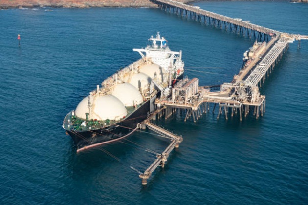
Source: Freeimages.com
The LNG is stored in large insulated tanks on shore and later pumped to regasification facilities before it enters the distribution system (figure 12).
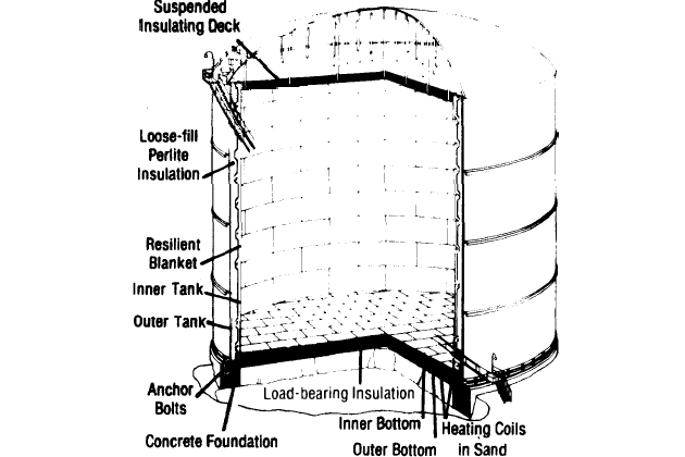
The storage capacity of the tanks is roughly equivalent to twice the capacity of a single LNG ship, but-unlike peak shaving storage tanks-the import terminal tanks are intended to hold LNG only briefly.
In either type of facility, the storage tanks represent a significant portion of the costs, and the gas industry has spent much time and money in research to develop effective storage systems.
Currently, there are four storage concepts:
- double-wall metal tanks;
- prestressed concrete tanks;
- frozen holes;
- mined caverns.
Techniques for storing liquids in aboveground tanks are well established and the LNG industry has drawn on these techniques. In addition, the tanks are surrounded by earthen dikes. These dikes are a safety measure, in that they could contain the entire contents of a tank in the event of a spill. However, they increase the land requirements for aboveground storage several times over. Much research has focused on the idea of underground storage tanks because little or no insulation other than the earth appears to be needed and there is no need for diking to contain spills.
Underground storage tanks have been built for LNG in the:
- United States,
- Algeria,
- England,
- Japan.
The US tanks were built for peak shaving operations in New Jersey and Massachusetts, but have since been abandoned in favor of other types of storage because the units failed to perform satisfactorily.
In any type of tank, the one hazard most often mentioned in connection with the storage of LNG is a phenomena known as «roll over».
Peak shaving plants have a greater potential for rollover due to weathering of the LNG and/or introduction of new LNG into a partially filled tank.
Rollover refers to the convection or motion of fluid which occurs when liquids of different densities exist in a storage tank. If different densities or stratification do occur within a tank such that a denser and warmer liquid is at the bottom of the tank and subject to heat leak, that liquid can ultimately become heated to the point that it is less dense than the liquid above it, and it will be rapidly moved by buoyant forces up the tank side walls to the surface. At this point, it experiences a sudden decrease in pressure and being above its normal boiling point vaporizes very rapidly in large quantities causing a significant pressure rise in the tank. As a result of this rapid expansion, cracks or even tank rupture can occur.
However, industry research on rollover has been extensive, resulting in deliberate controlled mixing of the tank contents, selected top, side, or bottom filling, careful monitoring of the temperature of the LNG contents throughout the tank, higher design tank pressures combined with low normal operating pressures, and improved venting. In addition, the potential of the phenomena occurring at a baseload plant is further reduced by an operational practice of unloading tankers into empty tanks, not partially filled tanks as can occur at peak-shaving plants.
From the storage tanks, LNG is pumped to the regasification plant where it is vaporized by heating it. Frequently, the LNG is heated in systems using the naturally occurring heat in nearby seawater. Other systems use process heat from other equipment or have heat exchangers fueled with:
- oil,
- electricity,
- gas,
- ambient air.
None of the vaporizer systems is proobviously the most economical or technically superior. The choice depends primarily on the location and design of a specific terminal and operaenvironmental regulations.
The regasification facility is one of the least costly sections of the terminal, but is considered important because if it should fail to operate, the entire purpose of the plant – to provide natural gas – will have been defeated.
LNG terminal siting
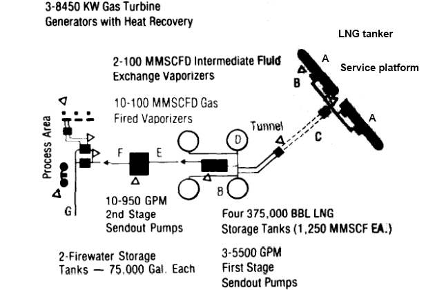
There are several factors related to proposed LNG import terminals that set them apart from the existing peak shaving plants (table 10).
| Table 10. Process flow data | ||||
|---|---|---|---|---|
| Location | Phase | Operating PSIG | Operating temp. | Max. flow rate |
| A | Vapor/Liquid | 1,0 | -260 °F | – |
| B | Liquid | 40,0 | -260 °F | 50 000 GPM |
| C | Liquid | 75,0 | -260 °F | 50 000 GPM |
| D | Vapor/Liquid | 2,0 | -260 °F | – |
| E | Liquid | 80,0 | -260 °F | 9 000 GPM |
| F | Liquid | 1 300,0 | -260 °F | 8 600 GPM |
| G | Vapor | 1 250,0 | 60 °F | 1 000 MMSCFD |
The proposed terminals are large-scale operations located in the coastal zone and major shipping channels, some in major harbors-ornear large population centers (figures 13 and 14).
They require large amounts of land and capital, and represent a large concentration of energy at a single site.
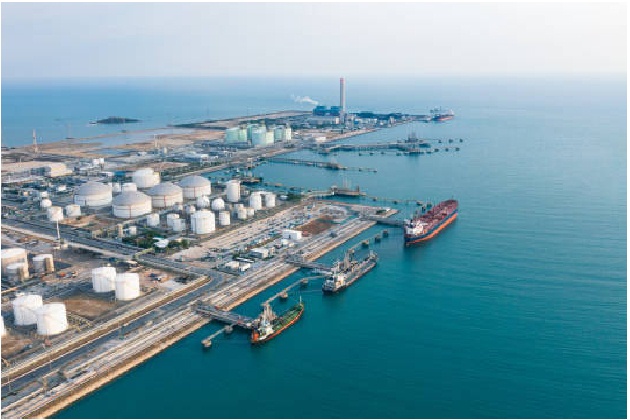
Source: Freeimages.com
The location of a terminal can be a major factor in its safety. The magnitude and extent of any damage from an LNG spill can depend on the proximity of the terminal and storage sites to other industrial and residential areas.
The site selection process is currently conducted by the company or consortium proposing the project. Gas industry officials consider such factors as:
- accessibility by large tankers, the availability of the market, which is largely determined by the proximity of an existing pipeline network;
- costs of land acquisition;
- availability of skilled labor supply;
- availability of public facilities such as roads, electricity, sewers, etc.
Some companies also consider area land-use characteristics and environmental sensitivities important aspects of site selection. The FPC position is that, unless otherwise stipulated, FPC approval of the facility allows Federal preemption of State and local laws relating to siting. Therefore, local and State land-use regulations could be overruled. A company makes application to the FPC only after it has done as much preliminary work as possible, which includes at least gaining control over, if not outright ownership of, the proposed site. Thus, neither the general public nor the Federal Government become involved in the site selection decision until it has already been made by the company. There are, at present, no Federal siting criteria, and those projects which are now proposed have a variety of sites, ranging from remote coastal and riverine areas with 1 000-acre buffer zones to as little as a 90-acre site on Staten Island.
LNG terminal regulation
The construction and operation of LNG terminals are primarily regulated by three Federal agencies:
- the Federal Power Commission (FPC);
- the Office of Pipeline Safety Operations (OPSO);
- the Coast Guard.
Federal Power Commission jurisdiction over the terminals is included in the process of licensing import projects. The FPC considers approval of any LNG import project to be «a major Federal action significantly affecting the quality of the human environment» subject to the National Environmental Policy Act requirement that an environmental impact statement (EIS) be prepared.
As a part of the EIS, the National Bureau of Standards cryogenics division in Boulder, Colo., under contract to FPC, reviews engineering and safety aspects of the proposed terminal. Also as part of the EIS, the FPC staff prepare a quantitative risk analysis, which is its principal method for determining whether a project can be considered safe. The risk analysis considers the major events which might cause an LNG spill such as:
- ship collision, grounding, or ramming;
- failure of the unloading arms or other major pieces of equipment;
- damage to the facility from natural phenomena or unusual accidents.
The risk analysis determines the extent of damage and the number of deaths and injuries which may result from a disaster and the probability that certain types of disasters would occur. The death probabilities from natural disasters are typically about 1 in 10 million. In some recent applications, the FPC rejected a site because it posed a public risk to life with a probability of greater than 1 in 10 million. Therefore, that figure has become the informal criteria which projects must meet for FPC approval.
The FPC exerts its influence over the facilities by attaching stipulations to the certification of public convenience and necessity which it issues if the project is approved. These stipulations are designed to minimize environmental consequences and to promote the safety of the facility. The applicant is required to comply with these stipulations if he accepts the certificate. Statements of compliance and operating reports are required regularly, but there is little or no post-certification oversight by the FPC. Onsite FPC inspection generally occurs only when a company wishes to expand its facilities and submits a new application.
The safety of the terminal facilities is largely an OPSO responsibility. Under the Natural Gas Pipeline Safety Act of 1968, OPSO is responsible for establishing minimum Federal safety standards for all pipeline facilities in or affecting interstate or foreign commerce. Pipeline facilities have been given an extremely broad interpretation to include all components of an LNG:
- import terminal;
- including the offloading facilities;
- storage tanks;
- regasification facilities and all associated pipelines.
Permits are not required by OPSO, which exercises its authority solely by inspecting facilities for compliance with Federal standards. The standards are currently built around the safety code of the National Fire Protection Association, known as 59(A). In addition to setting minimum standards for materials, equipment, and systems the code relies upon two basic concepts to protect the public from Hazards of LNG and Relevant GasesLNG hazards: the requirement for a diking and containment system and the requirement that specific distances be maintained between certain components and between components and the property line.
Dikes are the primary device used to prevent the uncontrolled spreading of an LNG spill on land (figure 15).
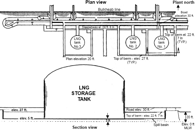
The dikes make it possible to use either of two methods of control:
- In the event of an LNG spill, the liquid can be contained within the dike and the rate of evaporation slowed by the use of high expansion foam. All sources of ignition can be eliminated. In this way, the LNG can dissipate in harmless concentrations into the atmosphere.
- Or, in the event of an LNG spill, the liquid can be contained within the dike and its evaporation controlled or even ignited so that it immediately burns in the confined space where the fire can be controlled by known firefighting methods.
The NFPA 59(A) regulations currently adopted by OPSO specify the size and construction of the dike and the design of related equipment necessary for the diking system.
The other technique used to enhance safety is to establish the distance which must lie between the dikes around the storage tanks and the property line. The distance required is one which would assure that heat from an LNG fire inside the dikes would not be severe enough at the property line to cause death or third degree burns.
Current regulations require that this distance be 0,8 times the square root of the area inside the dikes.
Regulations also require that the facility be designed to meet the maximum earthquake specifications of the Uniform Building Code.
New LNG terminal standards have been proposed by OPSO and are being circulated for public comment. Generally, the proposed standards are more strict and cover more aspects of terminal design than do current standards, but in many cases they are less definitive. The standards increase the distance between dikes and property line, require a vapor dispersion zone or a redundant automatic ignition system, and set more stringent seismic design criteria. It is expected that the proposed standards will seriously limit the choice of sites for LNG terminals.
The Coast Guard’s responsibility for terminal facilities is an extension of the Captain of the Port’s jurisdiction over waterfront facilities. The Coast Guard maintains that its jurisdiction, with regard to LNG vessel movements and waterfront facilities, is sufficient to promulgate and enforce safety requirements for the LNG transfer operations at the receiving terminal and, in that light, considers the pipelines between tanks and loading or offloading equipment, the loading and offloading equipment, storage tanks, and the entire portion of the LNG system which connects the tanker to the distribution system to be under its jurisdiction. The inland distribution system is not the responsibility of the Coast Guard.
The Coast Guard currently has no regulations specific to LNG terminals but has undertaken development of such regulations to implement appropriate sections of the Ports and Waterways Safety Act of 1972. In the meantime, the Captain of the Port in each area where LNG is handled exercises authority by developing contingency plans for operations.
A critique of the Government role in the regulation of LNG terminal siting and operations is included in the following chapter.
Trends in LNG USE and facilities
Liquefied natural gas could be an important short-term energy supply for the United States over the next few decades and could help alleviate some near-term fuel shortages in selected sectors of the economy. Ultimately, however, the supply of natural gas which may be sold to the United States as LNG is limited. LNG is not a major new source of energy which will allow unrestrained use of natural gas, and it is unlikely that many import projects will be forthcoming beyond those already proposed.
In the future, it can probably be expected that US consumption of natural gas will continue to decline slightly and it is possible as much as 15 percent of the total natural gas consumed could be transported as LNG by 1985-95 (figure 16).
This figure may be lower if a pipeline is used to transport Alaskan gas to the continental United States.
Imports of LNG to the United States currently come from Algeria, and there is some concern about the wisdom of becoming dependent upon any one country as the major source of supply. However, several other countries also control major portions of the world’s natural gas reserves. For example, liquefaction and export facilities are being developed in:
- Chile,
- Nigeria,
- Colombia,
and there is a possibility of additional export projects if technology and reserves are proven in:
- Russia,
- Iran,
- China,
- Australia.
It is likely that sponsors of some US import projects will turn to these exporters for additional supplies of LNG, thus reducing the dependency on Algeria.
Changes are also likely to occur in the sites chosen for US import terminal facilities, in some types of equipment which may be used, and in the onshore distribution of LNG.
Currently, public pressure exists for, and the industry trend is toward, «remote» siting of LNG terminals and storage facilities. Controversy over the meaning of remote and the characteristics which make a site acceptable for an LNG facility, coupled with the difficulty firms may have in finding acceptable sites, have led to the suggestion that LNG facilities could be located offshore, away from populated areas and congested harbors and waterways.
Several designs have been proposed for offshore platforms to house LNG facilities, but no detailed design has been developed for any specific site. At the present time, these preliminary designs limit site selection to locations with water depths of 600 feet. Most of the design concepts are self-contained facilities which look like large floating barges installed to a mooring system (figure 17).
Source: Freeimages.com
Other concepts propose that the platforms be floated to a site, then grounded to the beach or seabed. There are also two other, more elaborate concepts: One would make use of subsea storage structures, similar to those used in the North Sea to store oil, with a semisubmersible or tension-leg concrete platform moored above for the liquefaction or regasification plant. The other features separate moored or jack-up platforms for the process plant and the storage structures.
According to industry figures, offshore facilities will require 3 to 4 years construction time. Crude estimates range from $175 million to $220 million for a receiving terminal with a 500 million cubic feet per day regasification plant and storage for 200 000 cubic meters and from $350 million to $425 million for a 500 million cubic feet per day liquefaction plant.
There are many designs for LNG tankers and onshore facilities. However, with the limited operating experience now available, no particular designs for either ship cargo systems or onshore storage facilities have yet emerged as obviously superior. Therefore, it is likely that a variety of equipment will come into use as more projects are approved.
It is also possible that increased use of LNG will result in increased onshore transportation of LNG to secondary markets by means other than pipeline. Although the proposed baseload import terminals have no specific provisions for truck and rail shipment of LNG, such shipments appear to be possible and permissible in the future. Shipment by truck is already a reality at most peak shaving operations and from the import terminal at Everett, Mass.
Read also: Sources of ignition on ships carrying LNG/LPG
Prior to 1969, only a few LNG trucking operations had been attempted in this country, using equipment originally designed for liquid nitrogen service. Based on the success of the operations, equipment was designed and fabricated especially for LNG. It is estimated that there are 75 LNG trucks currently in operation in the United States. Typical of the trucking which has taken place was the shipment of nearly 4,5 million gallons of LNG from Philadelphia, Pa., to Lowell, Mass., during the winter of 1969. Since then large volumes have been transported all over the United States to help supply outlying communities, to provide temporary supplies when service is interrupted, and to provide small quantities for experimental work.
Liquefied natural gas could also be moved from import terminals or liquefaction plants by barges or railway tank cars.
The use of barges was first proposed to transport LNG up the Mississippi River to the Chicago Union Stockyards, and one barge was constructed and tested for this purpose in the 1950’s. It was never used commercially. Another barge, the 297-foot Massachusetts, was constructed by Distrigas for distributing LNG from a Staten Island import terminal. However, that barge has been taken out of service because of opposition.
Railway tank cars have been proposed as a means of carrying LNG to isolated areas which do not justify construction of pipelines. Tank cars now in use hauling liquid oxygen, nitrogen, and hydrogen would be suitable for LNG service, but the economics are such that it is unlikely there would be much emphasis on rail movement of LNG.
Existing and proposed projects in brief
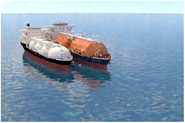
There are two operating LNG marine transport projects in the United States today, the «Distrigas» project importing gas from Algeria into Everett, Mass., and the «Phillips/Marathon» project exporting gas from Alaska to Japan. Construction of the first large baseload import project to be approved by FPC, «El Paso I», is nearing completion, and the facility is expected to become operational early in 1978 importing gas from Algeria to both Cove Point, Md., and Elba Island, Ga., (near Savannah).
One additional large import project has recently been given final approval by FPC, but no construction has begun. This is the «Trunkline» project to import LNG from Algeria to Lake Charles, La. The «Pacific-Indonesia» project to import LNG from Indonesia to Oxnard, Calif., has received only initial FPC approval and no construction has begun.
Three additional projects have been filed with the FPC for some time and decisions or approvals are expected soon. These are: the «El Paso II» project to import LNG from Algeria to Port O’Connor, Tex., the «Pacific-Alaska» project to transport LNG from Cook Inlet in southern Alaska to California; and the «El Paso-Alaska» project to transport the huge North Slope Alaska gas reserves from Gravina Point, Alaska (after pipelining from the North Slope) to California.
Since these eight projects have a reasonable probability of being operational in the future (the early 1980’s), a brief description of each is included in this section. Other planned or proposed projects have not been included for various reasons. For example: the «Eascogas» project which was planned for Staten Island, N. Y., and Providence, R. I., terminals has been delayed so many times that its viability is in question. A project planned by Tenneco to import gas from Algeria to St. John’s, N. B., in Canada, and then pipe the gas to the United State is now in the early review stages by FPC. Another recently announced project is one by the Peoples Natural Gas Company of Chicago to import LNG from either Iran or Chile to a terminal near Corpus Christi, Tex.
This report reflects the situation as of the summer of 1977. Many other projects are in the early planning states. Many factors affect these plans, however, and changes are common prior to actual construction of facilities.
The Distrigas project
This project has been in operation since 1971. The 50 000 cubic meter LNG tanker Descartes is now on a regular delivery schedule on approximately a 20-day cycle (figure 18).
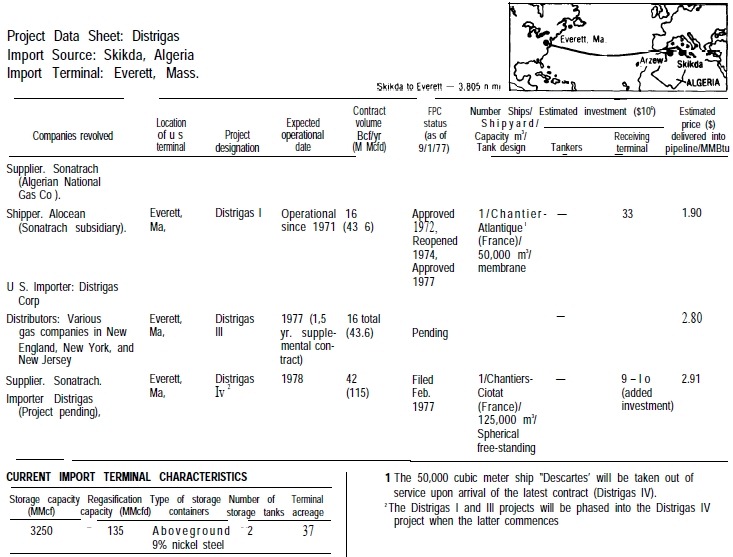
The ship, which was built in France in 1971 and operates under the French flag, has been delivering LNG from Skikda, Algeria, to the terminal at Everett, Mass., at the rate of about 15 trips each year. The terminal is located on the Mystic River, up from the main Boston harbor and less than one-half mile from the Boston city limits, in a highly industrialized region with both LPG and gasoline terminals adjacent to the property.
The Everett facility has operated without major incident for 6 years.
The principal market for this LNG is the Northeastern States with distribution made by both truck and pipeline. At present 40 percent of the LNG is distributed by trucks and more than 60 trucks operate out of the facility to other satellite storage tanks in the Northeast. The Distrigas project has contracted for a supply of 16 billion cubic feet of gas per year, and in 1976 actual imports totaled slightly over 10 billion cubic feet.
While this project has received FPC approval, a modification to expand the terminal and total import volume has been filed and is pending approval by FPC. Under the terms of a new 20-year contract with the Algerian National Gas Company, Distrigas would import 42 billion cubic feet of gas per year beginning in 1978. This contract would replace the existing one and a new 125 000 cubic meter ship, the Mostefa Ben Boulaid, would be used in place of the Descartes. Additional unloading facilities, but no new storage tanks, are planned for this expansion.
The Phillips/Marathon project
The oldest operating marine LNG project in the United States is the project now exporting gas from fields in Cook Inlet in southern Alaska, through a terminal at Kenai, to Neigishi, Japan. This project has been operated by the Phillips Petroleum Company and Marathon Oil Company since 1969 (figure 19).
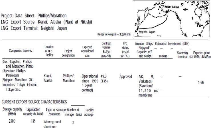
Two 71 500 cubic meter LNG tankers, the Arctic Tokyo and the Polar Alaska, were built in Sweden and operate under the Liberian flag with Italian crews.
The contract to supply Tokyo Electric and Tokyo Gas companies is for 135 billion cubic feet of gas per year, and in 1976 about 50 billion cubic feet were actually delivered. This project has operated without a major problem since initiation.
During the extreme winter of 1977 a special delivery of one shipload of LNG was made to Everett, Mass., from Alaska, after a waiver of the Jones Act prohibiting the use of foreign flag tankers in US trade. A French-built 3,5 000 cubic meter tanker, the Kenai Multina, flying the Liberian flag was used. This project contract expires in 1985. Beyond that, application may be made to bring the gas to southern California.
The El Paso I project
The agreement between El Paso Natural Gas Company and Sonatrach (Algeria) will lead to the initial transport of the LNG equivalent of 1 billion cubic feet per day (365 billion cubic feet per year) of natural gas to the United States (figure 20).
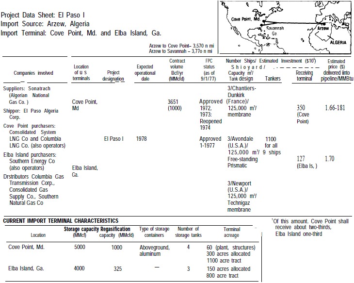
The Columbia Gas System, along with the Consolidated Gas System, has entered into contract for some two-thirds of this gas. The LNG will be delivered to a terminal located on the Chesapeake Bay at Cove Point, Md. The terminal will be jointly owned by Columbia and Consolidated and will become operational early in 1978. The remainder of LNG will be delivered to Southern Natural Gas at a new terminal under construction on Elba Island, Ga.
The Cove Point terminal has two tanker berths, four storage tanks and several process areas. The two tanker berths are located about 1 mile offshore along a 2 500-foot pier which is connected to shore by an underground tunnel containing both LNG pipes and vapor return lines. The initial operating plans call for about 140 ship arrivals per year. The Cove Point facility is located on a 1 100-acre tract of land along the Chesapeake Bay in Calvert County, Md.
The gas will be piped from Cove Point to an existing pipeline in Loudoun County, Va., and then to markets in middle Atlantic States served by Columbia and Consolidated Natural Gas Companies.
The Elba Island terminal is on an 800-acre site of undeveloped land, wholly owned by Southern Natural Gas. It is located 5 miles downriver from Savannah, Ga., and will supply gas to southeastern US markets. This LNG is expected to represent about 15 percent of Southern Natural Gas sales when the terminal is operational. It is planned that 50 LNG tankers will call at the Elba Island terminal each year, substantially increasing the ship traffic at the Savannah port entrance.
It will be interesting: Ship-to-ship LNG transfer operations
Nine 125 000 cubic meter LNG tankers are to be used to serve both El Paso I terminals. Three tankers were built in France, are now completed and laid-up, and are planned to be operated by El Paso under the Liberian flag. Six others are under construction at two US shipyards (Avondale and Newport News), and are planned to be operated by El Paso under U. S. flag.
The entire project is about 2 years behind schedule. The principal technical problem was completion of the large liquefaction facilities in Algeria. After one US contractor failed to perform, the Algerian National Gas Company canceled the contract and hired a new contractor. The U. S. terminals and the U. S.-built tankers are now almost completed, after a slow-down to await completion of the Algerian terminal. The present schedule is for LNG shipments to begin in January 1978.
The FPC approved the El Paso I project in June 1972.
The «Trunkline» project
The Trunkline project was approved by FPC on June 30, 1977, after an appeal of an initial opinion in April (figure 21).
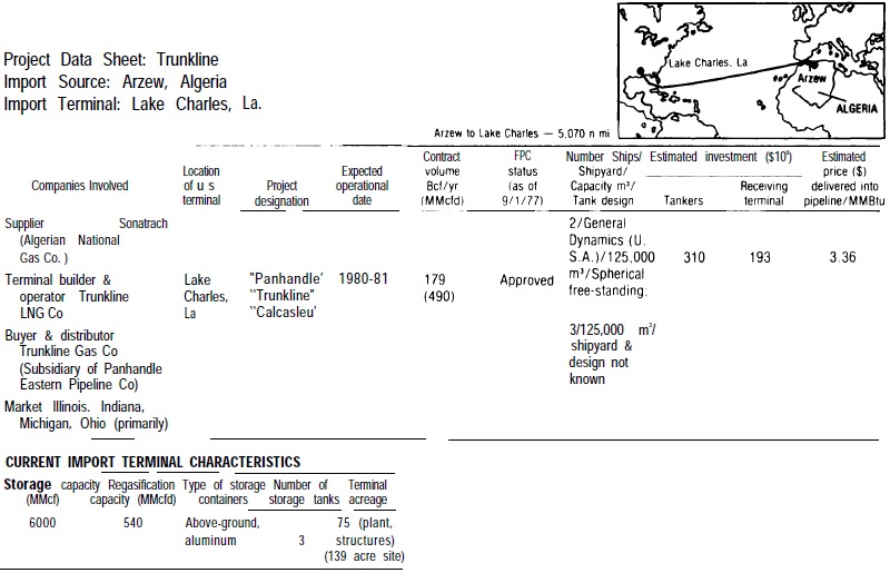
The proposed LNG facility would be near the Lake Charles Harbor in Louisiana and within the Terminal District Industrial Park. It would be located on a 139-acre site and would be used to unload, store, and ship LNG imported from Algeria. The LNG terminal would consist of a berthing dock for LNG unloading, an onshore facility consisting of three 600 000-barrel LNG storage tanks surrounded by a dike, two 25 000-gallon liquid nitrogen storage tanks, one 250 000 Bunker C fuel-oil tank for servicing the LNG tankers, and a process area which would contain equipment for all LNG transfer operations.
Ancillary facilities would include:
- offices;
- equipment for wastewater treatment;
- fire control and detection;
- fire protection equipment;
- water supply;
- electrical power;
- communications.
The project is planned for importing 179 billion cubic feet of gas per year using five 125 000 cubic meter LNG tankers. The tankers would reach the facility at the arrival rate of 65 per year through a 24-mile channel from the Gulf of Mexico.
Subsidiaries of Panhandle Eastern Pipe Line Company, General Dynamics, and Moore-McCormack Bulk Transport, Inc., have formed a partnership, Lachmar, to build, own, and operate two of the ships. These two ships are to be built at General Dynamics, Quincy, Mass., shipyard. The three other vessels for this project are expected to be provided by the Algeria National Shipping Company.
The «Pacific Indonesia» project
In an initial decision on July 22, 1977, an FPC Administrative Law Judge approved a proposal to import 200 billion cubic feet of gas per year from Indonesia to a terminal in Oxnard, Calif. The decision is subject to Commission review. There is considerable controversy in California over the site, and some State legislation on siting is pending (figure 22).
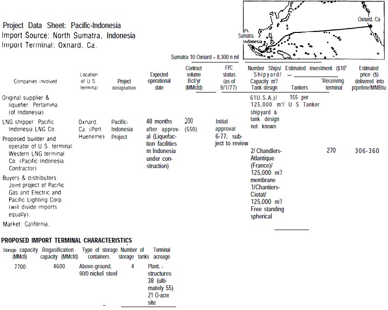
The proposed Oxnard facility would be owned and operated by Western LNG Terminals. It would be located on a 210-acre site in the City of Oxnard, on the coast of California. This plant would import LNG at a rate of 546 million cubic feet of gas per day for markets within the State of California. The LNG storage and vaporization facilities would occupy 38 acres of the site containing two to four 550 000-barrel, double-wall, above-ground tanks, 240-feet in diameter with an overall height of 129 feet. The plant facilities would require 55 acres of the site, and the marine terminal would occupy 34 acres of leased subtidal land extending approximately 6 000 feet offshore at Ormand Beach. Unloading arms at the marine terminal would transfer the LNG from the ship to the storage facilities through 42-inch cryogenic pipes.
Liquefaction facilities in Indonesia are now under construction.
Conditional agreements have been reached with shipping companies for nine 125 000 cubic meter LNG tankers. Pacific Indonesia will charter the ships, three of which will be French built and the remaining six US built. No U. S. ship construction contract has been announced.
The El Paso II project
The El Paso II project is pending before the FPC. The proposal is to transport 365 billion cubic feet of gas per year from Algeria to a new facility at Port O’Connor, Tex. TO A fleet of twelve 125 000 cubic meter LNG tankers would be required (figure 23).
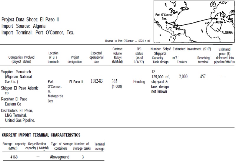
It is planned that six of these would be US flag and U. S. built, but no construction contracts have been announced. Safety reports have been submitted and FPC hearings were held during the summer of 1977. Draft and final environmental impact statements have been issued.
The «Pacific-Alaska» project
A project to transport LNG from Cook Inlet gas fields near Kenai, Alaska, to California is pending before FPC (figure 24).
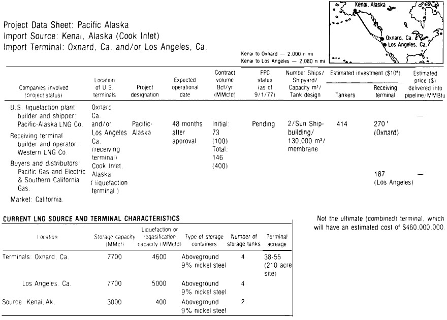
A terminal is planned at either Oxnard or Los Angeles, Calif. Questions of terminal siting now being addressed by the State of California are delaying some decisions on this project. It is planned that initially two 130 000 cubic meter tankers would be used to import 73 billion cubic feet of gas per year. Sun Shipbuilding Company has signed contracts for these ships with an affiliate of Pacific Lighting Company, but no construction has started.
The «El Paso-Alaskan» project
This project is one of the proposed transportation systems to deliver gas from the major Alaskan North Slope fields to the lower 48 States (figure 25).
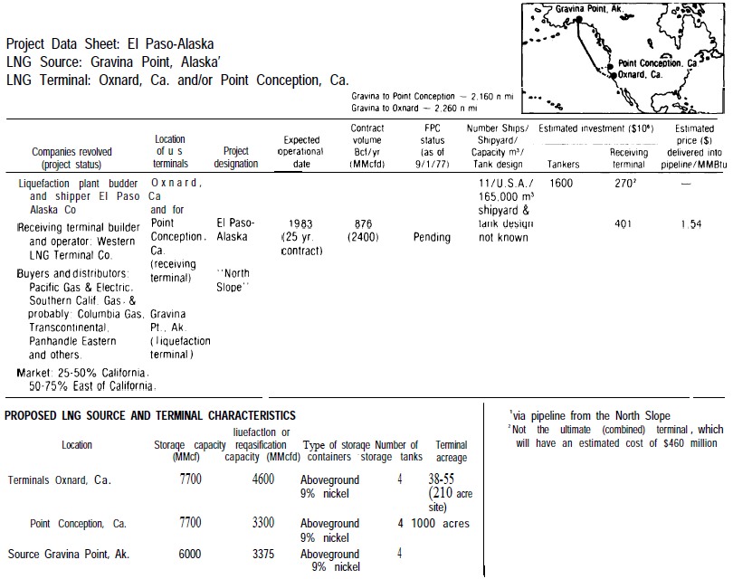
While the other systems involve gas pipelines through Canada, this project proposes a gas pipeline from the North Slope along the present oil pipeline route to southern Alaska, A liquefaction facility would be built at Gravina Point, Alaska, and an initial fleet of eight 165 000 cubic meter LNG tankers are planned to deliver the LNG from that point to California. Designs have been prepared for the tankers but no construction contracts have been discuseed.
Initially, the project is planned to deliver 876 billion cubic feet of gas per year with distribution both to California and other States to the east. A proposed ultimate distribution level of 1,17 trillion cubic feet per year would require 11 ships. A California terminal is proposed at Point Conception, with an alternate site at Oxnard. The Point Conception terminal would incorporate an offloading pier almost 1 mile offshore and an onshore storage and regasification plant.
Under the Alaska Natural Gas Transportation Act of 1976, the President is required to recommend to Congress on the selection of the best transportation system and Congress will then have 60 days to review this recommendation. The President’s recommendation was announced in favor of a trans-Canada gas pipeline on September 8, 1977, but formal recommendation had not yet been made to Congress at this printing.

- Transportation of Liquefied Natural Gas, September 1977.
- Federal Energy Administration, Monthly Energy Review, March 1977.
- U. S. Department of the Interior, Bureau of Mines, World Natural Gas Annual (Washington, D. C.: U. S. Department of the Interior, Bureau of Mines, 1975).
- «LNG Report», Pipeline and Gas Journal 204 (June 1977).
- Interview with Officials of Export-Import Bank of the United States, Washington, D. C., June 16, 1977.
- David Hawdon, World Transport of Energy 1975 to 1985 (London: Stanil and Hall Associates Limited, April 1977), p. 39.
- Federal Power Commission, «Table of LNG imports and exports for 1976», News Release, June 3, 1977, and Federal Energy Administration, Monthly Energy Review, March 1977.
- Office of Technology Assessment LNG panel meeting, Washington, D. C., June 23, 1977.
- Douglas M. Considive, cd., Energy Technology Handbook (New York: McGraw-Hill, 1977).
- American Gas Association, Gas Supply Review, 5 (February 1977).
- Federal Power Commission, Recommendation to the President Alaskan Natural Gas Transportation Systems (Washington, D. C.: Federal Power Commission, May 1, 1977) p. I-44.
- H. Magelssen, «LPG-Transportation Cost, Market Potential and Future Charterers», Gastech 76 Proceedings LNG and LPG Conference, New York, Oct. 5-8, 1976, (Herts, England: Gastech Exhibitions, 1977).
- Society of Naval Architects and Marine Engineers, Proceedings of Second Ship Technology and Research (STAR) Symposium (San Francisco, Calif.: May 25-27, 1977), p. 396.
- Telephone interview with staff of the Bureau of Mines, Pittsburgh, Pa., Sept. 7, 1977.
- Telephone interview with staff of Naval Weapons Laboratory, China Lake, Calif., Aug. 25, 1977.
- American Gas Association, LNG Information Book 1973 (Arlington, Va.: American Gas Association, 1973).
- U. S. Department of the Interior, Bureau of Mines, Report on the Investigation of the Fire at the Liquefaction, Storage and Regasification Plant of the East Ohio Gas Company, Cleveland, Ohio, Oct. 20, 1944. (Washington, D. C.: U. S. Department of the Interior, Bureau of Mines, February 1946).
- Socio-Economic Systems, Inc., Environmental Impact Report for the Proposed Oxnard LNG Facilities, Safety, Appendix B (Los Angeles, Ca.: Socio-Economic Systems, 1976), p. 10.
- U. S. Congress, House, Staten Island Explosion: Safety Issues Concerning LNG Storage Facilities. Hearings before the Special Subcommittee on Investigations of the Committee on Interstate and Foreign Commerce. 93rd Cong., first sess., July 10, 11, 12, 1973, pp. 143, 145.
- «LNG Scorecard», Pipeline and Gas Journal 204 (June 1977): 22.
- 15 U. S. C. § 717 f (c) (1970).
- 15 U. S. C. § 717 c (a) (1970).
- Interviewswith Federal Power Commission staff, Washington, D. C., May 31 and June 24, 1977.
- Edward Faridany, LNG: 1974-1990 Marine Operations and Market Prospects for Liquefied Natural Gas, (London: Economist Intelligence Unit Limited, June 1974), p. 69.
- Interviews with Officials of Distrigas Inc., Boston, Mass., .June 15, 1977.
- «LNG Scorecard», Pipeline and Gas Journal 203 (June 1976): 20.
- American Gas Association, «Update of Status of LNG Projects», Gas Supply Review 5 (February 1977): 8.
- U. S. Department of Commerce, Maritime Adminitration, Status of LNG Vessels (Washington, D. C.: U. S. Department of Commerce, Maritime Administration, March 15, 1977).
- U. S. Department of Commerce, Maritime Administration, Status of LNG Projects (Washington, D. C.: U. S. Department of Commerce, Maritime Administration, September 1976).
- Interview with official of General Dynamics Company, Boston, Mass., June 15, 1977.
- General Dynamics Gets Tanker Job for $310 million, Wall Street Journal, July 28, 1977.
- «Subsidized Shipbuilding Contract Awards» Statistical Quarterly (First quarter 1977).
- Interview with officials of Export-Import Bank of the United States, Washington, D. C., June 16, 1977.
- Department of Transportation, U. S. Coast Guard, Liquefied Natural Gas, Views and Practices Policy and Safety (Washington, D. C.: Department of Transportation, U. S. Coast Guard, Feb. 1, 1976), p. III-B (2).
- 33 C.F.R. $$6.04.8, 6.14.1 (1976).
- Department of Transportation, U. S. Coast Guard, The Port of Boston, LNG-LPG Operation/Emergency Plan (Boston, Mass.: Department of Transportation, U. S. Coast Guard, Mar. 29, 1977).
- Department of Transportation, U. S. Coast Guard, Liquefied Natural Gas, Views and Practices Policy and Safety, p. IV-3.
- Department of Transportation, U. S. Coast Guard, Liquefied Natural Gas, Views and Practices Policy and Safety, p. IV-4.
- Conversation with officials of Columbia LNG Corporation, Cove Point, Md., June 8, 1977.
- Interview with staff of Woodward-Clyde Consultants, Washington, D. C., June 28, 1977, and Federal Power Commission, Alaska Natural Gas Transportation System, Final Environmental Impact Statement, Vol. 111, p. 425d and 4253. (Washington, D. C.: Federal Power Commission, 1976).
- Interview with staff of Federal Power Commission, Washington, D. C., May 31, and June 24, 1977.
- U. S. Department of Transportation, Office of Pipeline Safety Operations, «Liquefied Natural Gas Facilities (LNG); Federal Safety Standards», Federal Register 42, no. 77, April 21, 1977, 20776-20800.
- «LNG Report», Pipeline and Gas Journal 204 (June 1977).
- Interviews with officials of Distrigas Inc., Boston, Mass., June 15, 1977.
- Dean Hale, «Cold Winter Spurs LNG Activity», Pipeline and Gas Journal 204 (June 1977): 30.
- Federal Power Commission, Trunkline LNG Cornpany et al., Opinion No. 796-A, Docket Nos. CP74-138-140 (Washington, D. C.: Federal Power Commission, June 30, 1977).
- Federal Power Commission, «FPC Judge Approves Importation of Indonesia LNG», News Release, No. 23292, July 22, 1977.
- Dean Hale, «Cold Winter Spurs LNG Activity»: 31.
- Federal Power Commission, «NGP-LNG Inc., Application and Request for Phased Proceeding», Federal Register 42, No. 131, July 8, 1977.
- Interviews with officials of Distrigas Inc., Boston, Mass, June 15, 1977.
- U. S. Department of Commerce, Maritime Administration, Status of LNG Vessels (Washington, D. C.: U. S. Department of Commerce, March 1977).
- Interviews with officials of Distrigas Inc., Boston, Mass., June 15, 1977.
- Federal Power Commission, United States Imports and Exports of Natural Gas 1976 (Washington, D. C.: Federal Power Commission, May 1977).
- Dean Hale, «Cold Winter Spurs LNG Activity»: 30.
- lnterviews with officials of Distrigas Inc., Boston, Mass, June 1977.
- U. S. Departrnent of Commerce, Maritime Administration, Status of LNG Vessels.
- Federal Power Commission, United States Imports and Exports of Natural Gas 1976.
- Dean Hale, «Cold Winter Spurs LNG Activity»: 21.
- Max Levy, «The Cove Point, Maryland LNG Terminal», Conference on LNG Importation and Terminal Safety, Boston, Mass., June 13-14, 1972.
- Southern Natural Gas Company, Facts on Elba Island, Savannah, Georgia LNG Terminal, (n. p.: Southern Natural Gas Company, n. d.).
- U. S. Department of Commerce, Maritime Administration, Status of LNG Vessels.
- Federal Power commission, Trunkline LNG Company et al., Opinion No. 796-A, Docket No s. CP74-138-140 (Washington, D. C.: Federal Power Commission, June 30, 1977).
- Federal Power Commission, Final Environmental Impact Statement Calcasieu LNG Project Trunkline LNG Company Docket No. CP74-138 et al., (Washington, D. C.: Federal Power Commission, September 1976).
- Federal Power Commission, «FPC Judge Approves Importation of Indonesia LNG».
- Federal Power Commission, Final Environmental Impact Statement Pacific Indonesia Project (Washington, D. C.: Federal Power Commission, December 1976).
- Federal Power Commission, Algeria II Project Outline of Contracts, El Paso Eastern Company, et al., Docket No. CP77-330, et al. (Washington, D. C.: Federal Power Commission, n. d.)
- U. S. Department of Commerce, Maritime Administration, Status of LNG Vessels.
- Federal Power Commission, Joint LNG Safety Report of El Paso Atlantic Company et al., Respecting the Proposed Algeria II Project, Docket No. CP73-258, et al. (Washington, D. C.: Federal Power Commission, Apr. 1, 1977).
- Federal Power Commission, Recommendation to the President Alaskan Natural Gas Transportation Systems (Washington, D. C.: Federal Power Commission, May 1, 1977).