Natural gas has solidified its position as a “clean” fuel alternative to traditional heavy fuel oils, driving a global increase in demand for its sea transport. The backbone of this critical infrastructure is the LNG carrier fleet. For decades, the steam turbine reigned supreme as the propulsion system of choice, largely due to its simple ability to utilize the natural boil-off gas from the cargo tanks. However, with rising natural gas prices and a persistent push for greater energy efficiency, this trend has shifted dramatically.
- Introduction
- Market Development
- Definition and types of liquefied gas
- Size of the LNG carriers
- Ship classes
- Distribution of LNG carriers today
- LNG carriers on order
- Distribution of propulsion systems on LNG carriers
- Average Ship Particulars as a Function of Ship Size
- Average design ship speed
- Propulsion Power Demand as a Function of Ship Size
- Average LNG carriers
- Propulsion Power Demand of Average LNG Carriers as a Function of Ship Speed
- Summary
This article, Propulsion Trends LNG Carriers, analyzes the evolution of the main engine types, focusing on the recent widespread adoption of high-efficiency dual-fuel diesel and diesel-electric systems, and examines how ship size and economic factors are shaping the future of maritime LNG transport technology.
Introduction
Natural gas is a “clean” fuel compared to diesel and heavy fuel oil and, together with an increasing environmental re-sponsibility, there is a rising demand for natural gas worldwide.
Where it is not possible to transport natural gas by means of pipelines, the LNG (Liquid Natural Gas) carriers have to take over the transportation because natural gas in liquid form at atmospheric pressure only takes up 1/600 of the natural gas volume. LNG is a clear liquid with a density of about 450 kg/m3, i. e. 45 % of the density of water. However, the liquid form at atmospheric pressure can only be maintained by boil-off of some of the gas.
The first LNG carrier was the 150 m3 forerunner Suehiro Maru No. 8 from 1962 (scrapped 1983) with a four-stroke diesel engine as prime mover.
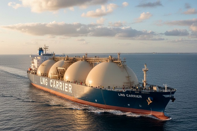
Source: AI generated image
However, since the second LNG carrier, the 27 400 m3 Methane Princess, was taken into operation in 1964 (scrapped in 1998), the steam turbine has almost exclusively been used as the main propulsion engine. The reason is the simplicity of utilising the boil-off gas in steam boilers to produce steam for the steam turbines, even though the conventional steam propulsion system has a low efficiency of about 28 % compared to the approx. 50 % valid for the conventional two-stroke diesel propulsion system.
Because of the relatively high price of natural gas today, it may be an economical advantage to utilise the expensive boil-off gas in a dual fuel (heavy fuel and compressed natural gas) diesel engine for main propulsion, as there will be no need for forced boil-off. A possibility is also to reliquefy the expensive boil-off gas by means of a reliquefaction plant, and then use an ordinary heavy fuel oil driven diesel engine for main propulsion. In both cases, fuel savings are obtained compared to the standard steam turbine system.
Market Development
Definition and types of liquefied gas
A liquefied gas has a gaseous form at normal ambient temperature and pressure, but is liquefied by pressurisation or refrigeration, or by a combination of both.
Most liquefied gases are hydrocarbons and flammable in nature. The main groups of gas cargoes are LNG (Liquefied Natural Gas), LPG (Liquefied Petrol Gas) and a variety of petrochemical gases.
LNG contains mostly methane naturally occurring in association with oil fields, whereas LPG contains the heavier gas types butane and/or propane. LPG is for example used as a bottled cooking gas. LPG may be carried in either the pressurised or refrigerated form (butane -5 °C and propane -42 °C), but in few cases also in the semi-pressurised form.
Read also: Best Practices and Strategies for Effective Cargo Tank Management
LNG is always carried/transported cold at atmospheric pressure, i. e. in its liquefied form at its boiling point of as low as -163 °C. As previously mentioned, in its liquid form, natural gas reduces its volume by 600 times and has a density of approx. 450 kg/m3. The LNG is always being refrigerated by means of its boil-off gas and, therefore, the LNG tanks will normally not be completely emptied because some of the LNG still has to cool down the tanks.
All liquefied gases carried in bulk must be carried on a gas carrier in accordance with the Gas Code rules of IMO (International Maritime Organisation).
Only LNG carriers will be discussed in this paper. Types of LNG carriers and their containment systems. The gas tankers are constructed according to the double-hull concept, including the bottom areas as a protection against ship grounding incidents.
Furthermore, the gas must be carried according to the so-called “cargo containment system” principle, i. e. the cargo tanks are installed separately in the ship’s holds, and are not a part of the ship’s structure.
The gas tanks (fully refrigerated at atmospheric pressure) used today in LNG carriers (see Fig. 1) are normally of the spherical (Moss) type, introduced in 1971, and membrane type, introduced in 1969, and in some few cases of the structural prismatic design. The spherical tanks and tanks of the structural prismatic design are self-supporting and are tied to the main hull structure.
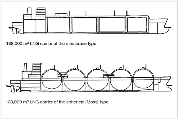
The tanks with the membrane wall system are rectangular and fully integrated into the hull and rely on the strength of the ship’s hull. The membrane system is based on a very thin primary steel barrier (0,7-1,5 mm membrane of stainless steel alloy) supported through the insulation. Such tanks, therefore, are not self-supporting, but only a relatively small amount of steel has to be cooled.
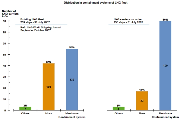
Today, membrane tanks are mostly being ordered because of its relatively higher utilisation of the hull volume for the cargo capacity, i. e. for the same cargo capacity, the ship dimensions are smaller than for a similar spherical (Moss) type LNG carrier, as also illustrated in Fig. 1, showing the ships in the same scale. However, the boil-off gas amount is higher for the membrane tank type compared to that of the spherical tank type.
The membrane systems have been greatly improved since the introduction in 1969, and especially over the last decade, they have, after the improvements, proved their suitability for LNG carriers.
About 55 % of the existing fleet in service (31 July 2007) consists of the membrane type, whereas about 80 % of the LNG carriers on order today (31 July 2007), in numbers, are based on the membrane types, see Fig. 2.
The main ship particulars of LNG carriers analysed in this paper are based on the two, and almost only used, main groups of LNG carriers:
- Spherical (Moss) containment system.
- Membrane containment system.
Size of the LNG carriers
The deadweight of a ship is the carrying capacity in metric tons (1 000 kg) including the weight of bunkers and other supplies necessary for the ship’s propulsion. The maximum possible deadweight tonnage of a tanker, for example, will normally be used as the size of the tanker.
The size of an LNG carrier is, however, normally not based on its deadweight tonnage, but on its obtainable volumetric capacity of liquid natural gas in m3.
Depending on the density of the LNG and the ship size, the volumetric LNG capacity, of course, corresponds to a certain deadweight tonnage, which normally, when referring to the design draught, is of the magnitude of 0,47-0,52 times the corresponding size in m3, and when referring to the scantling (max.) draught is of the magnitude of 0,52-0,58.
Ship classes
As mentioned earlier, there is a split up in LNG carriers, but this is based on the differences in the construction of the cargo containment system, as for example the spherical (Moss) and the membrane containment systems.
Depending on the ship size and particulars, the three main groups of merchant ships, tankers, bulk carriers and container vessels, are split into different main groups or classes, like handymax, panamax, etc.
However, for LNG carriers, there is no such similar general split-up into different groups or classes based on the dimensions alone. The reason is that ever since 1962, LNG carriers have normally been designed for specific purposes/routes and LNG terminals (with the resulting limitations to the ship dimensions) in large series of the same size.
Thus, the most common size of LNG carriers delivered or on order is between 120 000-180 000 m3, and often referred to as Conventional.
The demand for lower LNG transportation costs is most effectively met by increasing the LNG capacity of the LNG carriers. Thus, the LNG carriers to and from Qatar ordered over the last few years are of the large sizes of approx. 210 000 m3 and 265 000 m3, and referred to as Q-flex and Q-max, respectively.
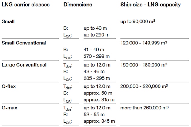
Thus, the LNG carrier classes often used today can therefore be referred to as listed in Table 1 and Fig. 3.
| Table 1. Main LNG classes | |
|---|---|
| Small | Up to 90 000 m3 |
| Small Conventional | 120 000-149 999 m3 |
| Large Conventional | 150 000-180 000 m3 |
| Q-flex | 200 000-220 000 m3 |
| Q-max | More than 260 000 m3 |
Med-max (Mediterranean maximum size) about 75 000 m3; Atlantic-max (Atlantic sea maximum size) about 165 000 m3
The first LNG carrier with a capacity of 150 m3 was introduced in 1962, and the second one of 27 400 m3 in 1964, and since the mid 1970s the maximum and commonly used LNG carrier size has been approx. 125 000-140 000 m3 for 30 years.
It will be interesting: LNG Bunkering Hazardous Zone: Safety, Classification, and Control
However, recently there has been a dramatic increase in the size of the LNG carriers ordered, with 266 000 m3 (Q-max) as the largest one (31 July 2007), but LNG carriers as large as 300 000 m3 are now on the project stage. The reason for this is that the larger the LNG carrier, the lower the transportation costs. This increase in ship size will also involve design modifications of new LNG plants and terminals. Today, the maximum loaded ship draught in service is still approx. 12 m, because of the limitations of the existing harbour facilities.
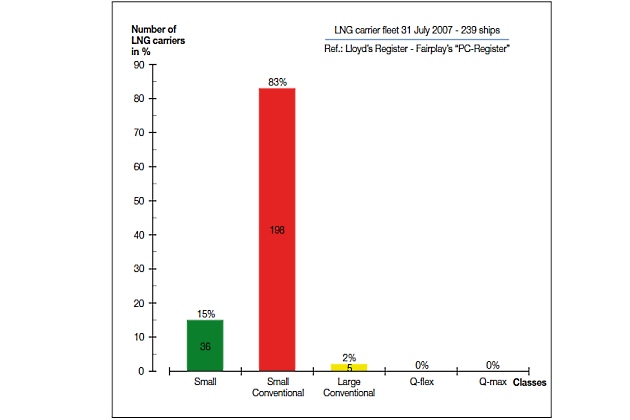
Distribution of LNG carriers today
As of 31 July 2007, the number of LNG carriers on order is 136, corresponding to about 57 % of the existing fleet in service (239), see Fig. 2.
Fig. 4 shows the split-up in LNG classes of the existing LNG carriers in service. As can be seen, the current fleet is dominated by relatively small ships of the “Small” and “Small Conventional” classes. Only 2 % of the LNG carrier fleet is larger than 150 000 m3 (Large Conventional).
LNG carriers on order
However, according to Fig. 5, which shows the LNG carriers on order as of 31 July 2007, the distribution of the fleet on LNG classes will change drastically.
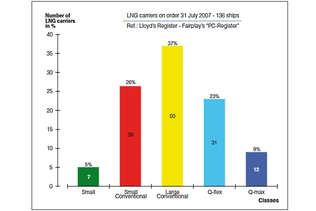
Thus, the number of large LNG carriers ordered over the last three years has increased greatly during this period.
At the same time, the contracting of “Small” ships has come to a complete standstill. On the other hand, some “Small Conventional” LNG carriers have been ordered as well, probably because of the application for a specific trade/route.
Fig. 6 shows, as indicated in Fig. 5, that large LNG carriers like the “Large Conventional” and Q-flex and Q-max will enter operation in the coming years.
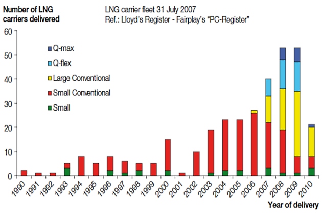
Fig. 7, which shows the average ship size of the ships delivered, also confirms that the average LNG size to be delivered will be larger in the future.
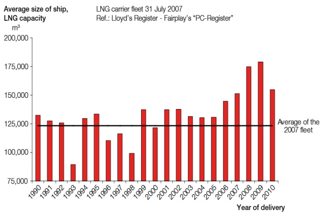
However, because many small LNG carriers have also been ordered, the average LNG size may not be as high as expected. Until now, very few LNG carriers have been scrapped.
Distribution of propulsion systems on LNG carriers
Of the ships on order as of 31 July 2007, 33 % are with two-stroke diesel engines and reliquefaction, 26 % with diesel electric propulsion and 40 % with steam turbine propulsion, see Fig. 8.
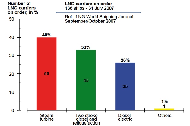
Fig. 9 shows the distribution of the propulsion systems chosen in the LNG fleet delivered or on order as of 31 July 2007, and shown as a function of year of delivery.
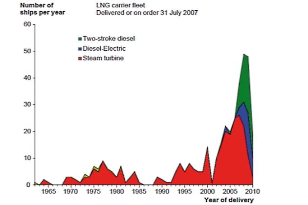
This curve also confirms the emerging shift from steam turbine to diesel.
Average Ship Particulars as a Function of Ship Size
On the basis of LNG carriers built or contracted in the period 1997-2007, as reported in the Lloyd’s Register – Fairplay’s “PC-Register”, we have estimated the average ship particulars of the different sizes of LNG carriers based on the spherical (Moss) and the membrane containment systems, respectively.
However, as only very few LNG carriers of some ship sizes have been built in this period, for these ship types, it has also been necessary to look back to the time before 1997.
Average hull design factor, Fdes
Based on the above statistical material, the average design relationship between the ship particulars of the LNG carriers can, as an indication, be expressed by means of the average hull design factor, Fdes, see below and Fig. 10:
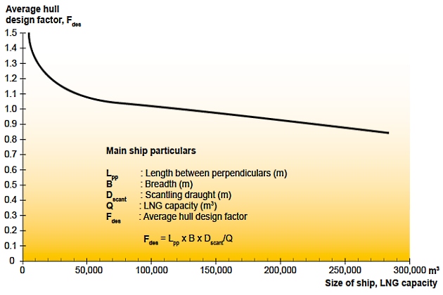
where:
- LPP – length between perpendiculars (m);
- B – ship breadth (m);
- Dscant – scantling draught (max.) (m);
- Q – LNG capacity (max.) of ship (m3).
Based on the above design factor Fdes, any missing particular can approximately be found as:
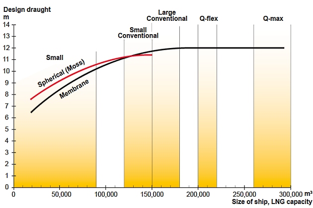
In Figs. 11, 12 and 13, the first three ship particulars are shown as a function of the ship size in LNG capacity (Q). The main groups of LNG carrier classes are also shown.
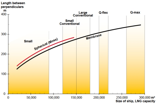
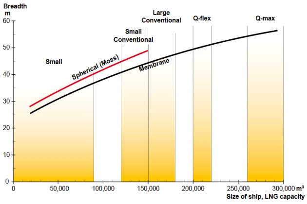
The ship particulars of the Moss type ships are only shown up to about 150 000 m3 as being the largest one built of this containment type.
Average design ship speed
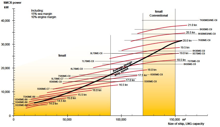
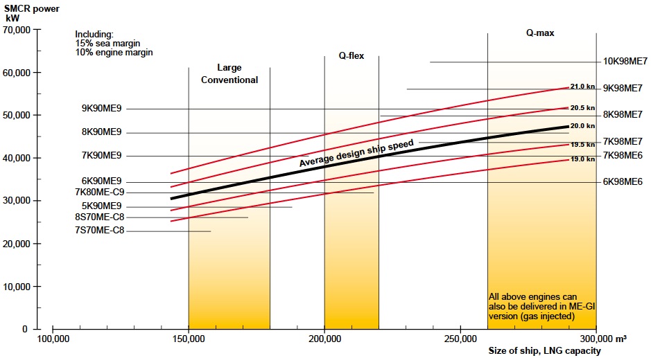
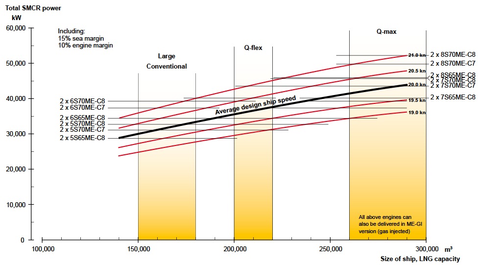
In Fig. 14, the average ship speed Vdes, used for design of the propulsion system and valid for the design draught of the ship, is shown as a function of the ship size. The design draught is normally from 5 % to 10 % lower than the scantling draught (max. draught) used for calculations of the hull strength.
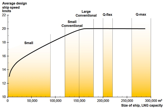
The larger the LNG capacity of the ships, the higher the ship speed, and today the average design ship speed is about 20 knots for ships larger than 150 000 m3.
Propulsion Power Demand as a Function of Ship Size
Average LNG carriers
Based on the average ship particulars and ship speeds already described for LNG carriers built or contracted in the period of 1997-2007, we have made a power prediction calculation (Holtrop & Mennen’s Method) for such LNG carriers in various sizes from 19 000 m3 to 265 000 m3. However, as the membrane type LNG carrier seems to become the dominating type in the future, cf. Fig. 2, a power prediction has only been made for LNG carriers of this type.
For all cases, we have assumed a sea margin of 15 % and an engine margin of 10 %, i. e. a service rating of 90 % SMCR, including 15 % sea margin.
It will be interesting: Description of LNG technology and import system
Furthermore, the size of the propeller diameter is assumed to be as high as up to approx. 76 % of the design draught, because the ships are normally sailing with a big draught also in ballast conditions (low density cargo).
The average ship particulars of these LNG carriers are shown in the tables in Fig. 15, and Figs 16 and 18 valid for LNG capacity 19 000-138 000 m3 and 150 000-265 000 m3, respectively.
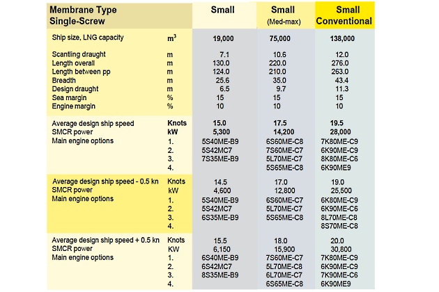
On this basis, and valid for the design draught and design ship speed, we have calculated the specified engine MCR power needed for propulsion. The maximum design draught for the large LNG carriers in service is limited to about 12,0 m because of harbour facilities. This results in beam/design draught ratios being relatively high (above 4.0).
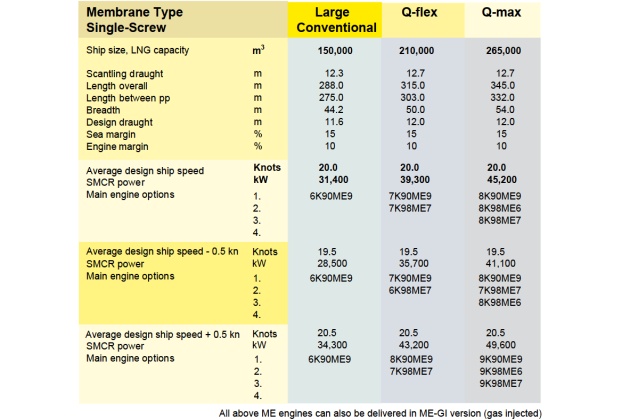
In such a case, a twin-skeg/twin-screw solution will be an attractive alternative to the standard single-screw solution, as a potential reduction of the propulsion power up to 9 % is possible.
Therefore, the large LNG carriers, besides the single-screw version, see Fig. 16, have also been calculated for the twin-skeg/twin-screw solution, see Fig. 17.
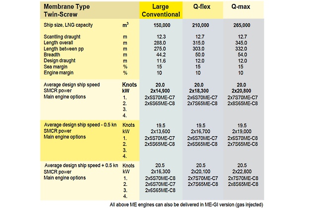
The twin-skeg/twin main engine LNG carrier would also meet the safety demands of the future to install at least double propulsion drives enhancing the redundancy of the prime movers.
In fact, the Q-flex and Q-max ships have only been made/ordered in the twin-skeg/twin-screw version.
The SMCR power results are also shown in the tables in Figs. 14-17 “Ship Particulars and Propulsion SMCR Power Demand” together with the selected main engine options of the MAN B&W two-stroke engine types. The similar results valid for +/-0,5 knots compared to the average design ship speed are also shown.
Propulsion Power Demand of Average LNG Carriers as a Function of Ship Speed
When the required ship speed is changed, the required SMCR power will change too, as mentioned above, and other main engine options could be selected. This trend – with the average ship particulars and average ship speed as the basis – is shown in detail in Figs. 18 and 19 for single-screw vessels, and in Fig. 20 for large twin-skeg/twin-screw vessels.
It is possible to derate the engine, i. e. use an SMCR power lower than the nominal MCR power, if the nominal MCR power needed for a given main engine is too high for a required ship speed. This would also result in a lower specific fuel consumption of the engine.
Therefore, in some cases it could be of particular advantage, considering the high fuel price today, to select a higher mark number than needed and derate the engine.
Summary
Safety and reliability of LNG carriers have always been important demands to the design of this type of ship, as can also be seen from the stringent standards given by IMO and several countries. Thus, the most widely used LNG containment systems – the Moss and the membrane – have been applied for many years because of their reliability.
Today, the membrane type LNG carrier seems to take over the major market share because of its better utilisation of the ship’s hull volume. For many years the steam turbines have almost exclusively been used as prime movers for LNG carriers, even though its efficiency is much lower than e. g. directly coupled two-stroke diesel engines. The reason is the simplicity of utilising the boil-off gas in steam boilers to produce steam for steam turbines.
However, with the introduction of the reliquefaction plant and/or gas-driven diesel engines some few years ago, it is today also possible to install high-efficiency diesel engines as prime movers, and thereby cut the fuel costs.
Read also: How to Conduct Simultaneous Operations during LNG Bunkering
The LNG carrier market is an increasingly important and attractive transport segment which, due to the increasing global demand to “clean” fuel, is expected to become of even greater importance in the future. Thus, the CO2 emission by burning LNG is about 23 % lower than for heavy fuel oil.
As described, MAN B&W engines are able to meet the engine power needs of any size in the modern LNG carrier fleet.
It should be noted that today the alternative Compressed Natural Gas (CNG) transportation form has potential to match the LNG transportation form for shorter routes. Is now being investigated, but has so far not yet been materialised in a ship, even though there are some projects with CNG carriers.
CNG’s gas density is about 2/3 of LNG. The advantage of CNG is that, in contrast to LNG, CNG does not need any costly processing plants to offload the gas. The tanks have to be of the cylindrical pressure types or of the coselle type, i. e. of the coil/carousel type. Also for this ship type, the MAN B&W two-stroke diesel engines are feasible.

- Introduction to LNG Center for Energy Economics The University of Texas at Austin January 2007.
- Liquefied Gas Handling Principles on Ships and in Terminals McGuire and White Witherby & Company Limited, London Third Edition 2000.
- LNG World Shipping Journal September/October 2007.
- LNG Carriers ME-GI Engine with High Pressure Gas Supply System MAN Diesel A/S, Copenhagen, Denmark, January 2007.
- The Trans Ocean Gas CNG Transportation Technical & Business Development Plan Trans Ocean Gas Inc. April 2004.
- Datta, A. (2022). INSights into the Global LNG Carrier Market: Prospects and Forecasts through 2030. Journal of Energy Resources Technology, 144(12), 12001. doi:10.1115/1.4050490.
- Iversen, E., & Foote, D. (2022). LNG Carrier Design and Construction: Safety and Efficiency Challenges. International Journal of Maritime Engineering, 163(A3), 1-14. doi:10.3940/rina.ijme.2022.A3.
- Zhang, Y., & Wang, Z. (2023). LNG Carriers and Their Propulsion Systems: An Overview of Current Trends and Future Developments. Marine Technology Society Journal, 57(2), 22-36. doi:10.4031/MTSJ.57.2.03.
- Huan, T., Hongjun, F., Wei, L., & Guoqiang, Z. (2022). Options and Evaluations on Propulsion Systems of LNG Carriers. In Propulsion Systems (pp. 45-67). IntechOpen. doi:10.5772/intechopen.107028.
- Aneesh, A., & Mohan, P. (2023). Market Dynamics of LNG Carriers: Trends and Innovations. Journal of Shipping and Trade, 8(1), 1-15. doi:10.1186/s41072-022-00138-8.
Did you find mistake? Highlight and press CTRL+Enter