Liquefied Natural Gas (LNG) is a strategic energy resource with constantly expanding applications in shipping and fixed facilities. The use of LNG is associated with unique technological risks stemming from its cryogenic and highly flammable properties. Potential incidents, such as uncontrolled leaks, fires, or explosions, mandate the compulsory implementation of comprehensive and strictly regulated safety measures. Consequently, the development, implementation, and verification of an adequate LNG Emergency Response Plan is a fundamental requirement for mitigating risks to personnel, the environment, and assets. The plan must ensure a controlled sequence of actions, covering the entire response spectrum: from primary prevention to the complete elimination of consequences.
- Introduction
- Scope
- Emergency Systems
- Emergency Systems – Layered Defence
- 1st Layer Safeguards (Prevention)
- 2nd Layer Emergency Systems
- 3rd Layer Emergency Systems
- LNG Fire Safety and Firefighting
- Basic Principles & Procedures
- Fire Extinguishing Agents
- Emergency plans in LNG bunkering
- Emergency Response Plan
- Data and Information to be included in the Emergency Plans
- Internal emergency plans
- External emergency plans
- OECD Guiding Principles in EPR
This article is dedicated to the analysis of the mandatory components of an effective emergency preparedness system. We will examine the concept of Layered Defence; the specifics of LNG fire safety and firefighting agents; and the requirements for structuring and detailing internal and external response plans. Particular attention is given to integrating the standards and principles outlined in the OECD Guiding Principles in EPR to ensure full compliance with international preparedness and response standards.
Introduction
Having already addressed Safety aspects of LNG as Fuel in article LNG Bunkering Risk Assessment“Assessing the Safety Risks of LNG Bunkering”, where LNG hazards have been identified and LNG risk & safety has been addressed, the present article is focused on the last stage of an LNG bunkering incident escalation, following an LNG accidental release, followed by expected LNG evaporation and formation of dispersing cloud.
The present article outlines a first informative section part with elements relevant for identification of Emergency Shutdown System (ESDS) on Liquefied Gas CarriersEmergency Systems and, a second part with LNG Firefighting techniques relevant for LNG firefighting in LNG and, finally, one last part on Emergency Plans, outlining recommendations to PAAs with regards to good practice in Emergency Response Plans, with a particular focus on the need for integration between LNG bunkering Internal Emergency Plans (BFO/PAA) and External Emergency Plan (Emergency Services and competent local/national authorities).
Scope
Having already addressed Safety aspects of LNG as Fuel in article LNG Bunkering Risk Assessment“Assessing the Safety Risks of LNG Bunkering”, where LNG hazards have been identified and LNG risk & safety has been addressed, the present section is focused on the last stage of an Guide LNG Bunkering Incident Reports Land Sea and Port LevelsLNG bunkering incident escalation, following an LNG accidental release and developing. The scope is indicated below, making use of the 3 Layers of Defence defined in ISO/TS 18683, as adapted below in a diagram below from DNV-GL Recommended Practice DNVGL-RP-G105.
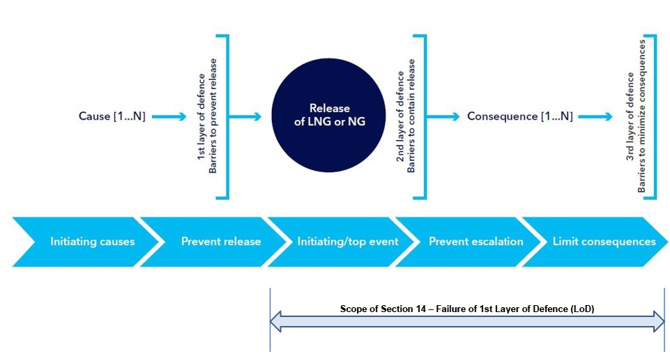
For the purpose of the present Guidance the scope for the Emergency Response activation should be considered the failure of the 1st LoD.
Systems composing the 1st LoD will be the constituent elements of the LNG bunkering transfer system:
- hoses;
- connectors;
- supports;
- loading arms and other elements as described in “Emergency Systems – Layered Defence”.
The 2nd LoD will follow the release event, or be actuated just before a high probability of release is verified (such as prior to a collision or other external accidental factor). This is the case of ESD systems, and ERC, with action in the bunkering line aiming to limit the amount of released LNG in the case of loss in the containment of the transfer line.
Emergency Systems
In spite of all technical and operational safeguards and measures, the possibility of an List of the Emergency Situations which can happen on the Liquefied Gas Carrieremergency situation shall always be taken into account. The safety concept as described in ISO/TS 18683 is here used to identify the relevant safeguards/barriers within the typical LNG bunkering/transfer system.
Read also: LNG Regulatory Framework International and European Maritime Safety Overview
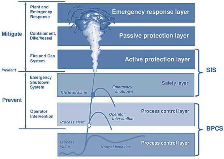
Figure 2, below, represents the escalation of an LNG bunkering incident with an accidental event line represented as a stepping-up on the severity of the incident through all the layers from normal process control, up to Emergency Response, the final stage of the mitigation action, following a release event.
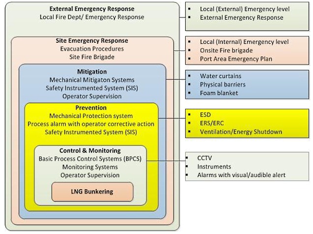
On Figure 3 the hierarchy of control and emergency systems is represented, for the particular case of LNG bunkering.
Emergency Systems – Layered Defence
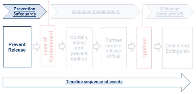
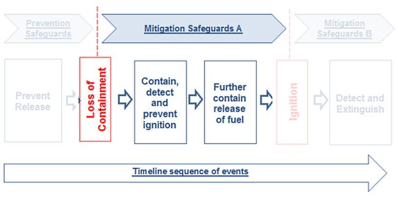
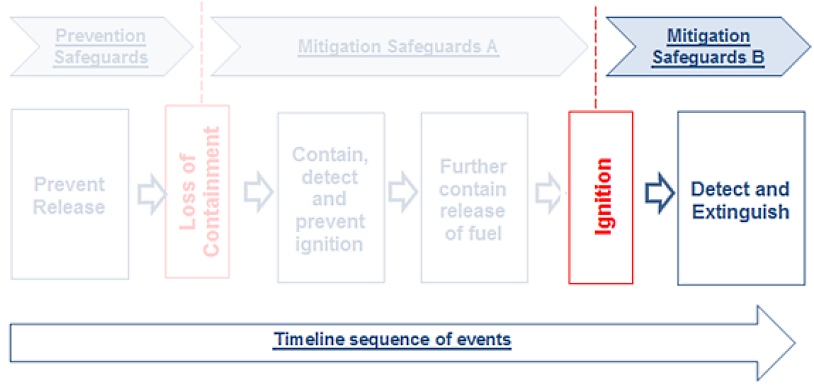
Another way of representing the 3 Layers of Defence (LoDs) is through the diagram in figure 4 (below). The sequence is simple and also reflects the 3 layers as in figure Strategies for Effective LNG Bunkering Operations and Their Execution“TTS Bunkering. Truck-to-ship LNG delivery of LNG, with truck ashore, alongside of the ship, at berth”:
- Prevent release;
- Contain release;
- and Extinguish fire.
The sequence implies a staged failure of the different safeguards, first with the transfer system failing to contain the LNG, second with the ESD and ERC activated to further contain and minimize release and, third and final, with an ignition event leading to a fire.
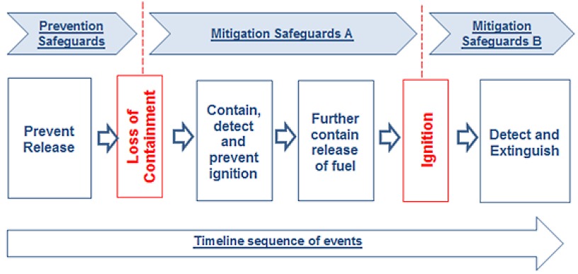
Prevention and Mitigation safeguards must be in place to address the full layers of defence, with the emergency action flow, following an accidental release.
1st Layer Safeguards (Prevention)
1st Layer systems are not emergency systems in themselves but contribute to the overall safety of the LNG transfer system through adequate containment of LNG. They operate under normal parameters and should allow ensuring that no LNG is released or spilled during normal operation. The standard is, in fact, zero-leak – zero-emission, not only accounting for Safety but also for environmental aspects with the need to ensure adequate methane emission mitigation.
The 1st layer systems are all the transfer system components necessary to ensure the necessary goal for the zero-leak – zero-emission standards.
In the present article two different types of 1st layer safeguards are listed:
- Technological;
- and Operational (mostly as part of Pre-Bunkering procedures).
Table 1 includes a summary of technological 1st layer safeguards and, in table 2, some relevant operational 1st Layer measures are also listed.
| Table 1. LNG Bunkering Layers of Defence (1st Layer of Defence – Prevention) (Technological Measures) | ||||
|---|---|---|---|---|
| 1st LoD System | Short description | Functional Requirements | Reference | |
| Bunker hose | 1st LoD system that allows transfer of LNG within proper containment element. | The bunker hoses shall be designed for cryogenic liquids, de-pressurisation, inerting and gas freeing. | ISO/TS 18683 (Tables 1 and 2) ISO 20519 (Table 1, Para 4.5.4) EN 1474-2 EN 12434 IACS Rec.142 Section 5.2.2 | |
| Connected at both ends of the transfer system, with QC/DC connector. | Correct hose length to take into consideration the vessel’s relative freeboard changes and movements. The limiting parameter for the hose dimension is the flow velocity. The industry practice is for the flow velocity not to exceed 10 m/s. | |||
| Loading arm (Hose Support/ saddles) | Hose suspension support to allow LNG bunkering hose to be handled avoiding mechanical damage and excessive bending of the hose. | If used, shall comply with and be designed to safely support the loads (static and dynamic) imposed by the LNG transfer operations during hose connection, transfer operations, and when the hose is disconnected under emergency conditions. | EN 1474-1 EN 1474-3 | |
| Act as a 1st LoD in the sense that it allows proper use of the bunkering hose, avoiding stresses due to bending. | ||||
| QCDC bunker connectors | Quick Connect-Disconnect Coupling LNG bunkering connector. | The coupling consists of a Nozzle (male) and a receptacle (female). The nozzle allows quick connection and disconnection of the fuel supply hose to the receptacle, mounted on the LNG manifold. Connectors used shall be designed to operate as quick connect/disconnect couplings. Couplings, in nominal sizes up to 6″, for flows up to 650 m3/h, and maximum flow rates of 10 m/s and shall conform to the functional requirements listed in ISO 20519. | ISO 20519 (outline of functional requirements) ISO 21903 (under preparation) | |
| Standardization work ongoing. | LNG Bunker connectors – QC/DC (Marine LNG fuel bunkering quick connect/disconnect coupling), following the functional requirements outlined by ISO 20519, but taking the work up to the level of International Standard. NWIP ISO 21903 | |||
| Fundamental 1st layer safeguard. Need to ensure the use of a standard type of QCDC connector for improved Safety levels. | ||||
| Bunkering connections | Bunkering Connections are fundamental to ensure safe operation, leak free and all allowing for dry-disconnect. | Bunkering connections shall all be arranged in order to allow dry disconnect operation and may be one of the following types: | a. Flange bolting assembly; | ISO/TS 18683 (Tables 1 and 2) ISO 20519 (Table 1, Para 4.5.4) |
| b. Manual coupler on standardized flange (without check valves); | ||||
| Disconnection after purging and inerting. | c. Hydraulic coupler on standardized flange (without check valves) or; | |||
| d. Dry connect/disconnect coupling. | ||||
| Vapour Return | Vapour return line allows excessive BOG in the receiving tank to be returned for condensation, liquefaction or GCU. | The vapour return line should follow all applicable requirements for the bunkering hose. | IACS Rec. 142 Section 5.9. | |
| Vapour return line(s) may be used in order to control the pressure in the receiving tank or to reduce the time required for bunkering (refer to IACS Rec.142, section 2.4.6 of Chapter 3). | ||||
| The most relevant factors that will affect the amount of flash gas generation in a typical bunkering operation are as follows (IACS Rec. 142, Section 5.9): | • Cool down of the transfer system; | |||
| • Difference in the conditions prevailing between the bunkering facility tanks and the receiving tanks (particularly the temperature of the receiving tank); | ||||
| Is here indicated as a 1st layer safeguard because it actually represents a mechanism to avoid release (due to excessive pressure in the receiving tank). | • Transfer rates (ramp up, full flow, ramp down/topping up); | |||
| • Heat gain in pipe line between bunkering facility tank and receiving ship tank; | ||||
| • Pumping energy. | ||||
| The LNG vapour return line will allow the collection of all excessive BOG to re-liquefaction, condensation or GCU. | ||||
| Table 2. LNG Bunkering Layers of Defence (1st Layer of Defence – Prevention) (Operational Measures) | ||||
|---|---|---|---|---|
| 1st LoD System | Short description | Functional Requirements | Reference | |
| Compatibility Assessment | 1st LoD system that allows transfer of LNG within proper containment element. | Compatibility Assessment should consider as a minimum (IACS Rec.142, section 1.4.2) | • Communication system (hardware, software if any and language) between the PIC, ship’s crew and BFO personnel; | IACS Rec.142 Section 1.4.2 SGMF Guidelines Section 6.4.2 |
| • ESD system; | ||||
| • Bunker connection; | ||||
| • Emergency release system (ERS) or coupling (ERC); | ||||
| • Vapour return line when appropriate; | ||||
| • Nitrogen lines availability and connection | ||||
| Connected at both ends of the transfer system, with QC/DC connector. | • Mooring equipment; | |||
| • Bunker Station location; | ||||
| • Transfer system sizing and loading on manifold; | ||||
| • Location of ERS; | ||||
| • Closure speed of valves; | ||||
| • HAZOP results as applicable. | ||||
| Communications | Communications in LNG bunkering should be able to ensure safe operation under normal conditions, allowing all parts involved to share information | Communications should be guaranteed between BFO and RSO by, at least, 2 different communication means – one Main and one other for a contingency communication plan. | IACS Rec.142 Section 1.4.2 SGMF Guidelines Section 6.4.2 | |
| A communication plan should be agreed between all parties involved prior to the start of operations. | ||||
| Communications equipment to be used within Hazardous Zones to be Ex-proof classified. | ||||
Even though the 1st Layer defence systems are not, in themselves, emergency systems, they are fundamental in defining the safe normal operation system where the containment of LNG is the most important functional design objective. The General Arrangement of LNG Custody Transfer SystemLNG transfer system is complemented by adequate procedures and training. Adequately mapped processes and trained staff are also, in themselves, 1st LoD safeguards.
2nd Layer Emergency Systems
Following the accidental release of LNG, the 2nd LoD will act to contain the leakage as much as possible and to prevent the ignition of the fraction of released LNG. Such measures are here identified as “Mitigation A” measures. Only loss of containment of the LNG transfer system is considered.
3 (three) different “Mitigation A” measures are considered:
- Automatic shut-down/dry-breakaway – ESD/ERS.
- Detection – Leakage Detection systems (CCTV, Gas detection, temperature).
- Containment barrier – Water curtains, Cryogenic protection.
The 3 different groups of systems above all contribute to an immediate containment active and passive response in the event of an accidental LNG release during LNG bunkering. The first group will, in fact, work for an effective minimization of LNG release in the event of a rupture or other accidental event.
| Table 3. LNG Bunkering Layers of Defence (2nd Layer of Defence – Mitigation A) (Operational Measures) | ||||
|---|---|---|---|---|
| 2nd LoD System | Short description | Functional Requirements | Reference | |
| ERS/ERC | The LNG transfer system shall be fitted with an emergency release system (ERS) and an emergency shut-down system (ESD) which are interconnected with a ship/shore or ship/ship ESD link to ensure the coordinated operation of both the ESD and ERS functions | The ERS shall be designed to protect the transfer system and the connections by disconnecting the transfer system, primarily should the ship drift out of their operating envelope. | IACS Rec.142 Section 1.5.9, 1.5.10 SGMF Guidelines ISO/TS 18683 (Functional requirement F18) ISO 20519 (Section 4.3) | |
| The ERS shall consist of an emergency release coupling (ERC), including interlocked isolating valves to minimise loss of LNG or NG when the ERC parts, and for transfer systems 4″ or larger in diameter, sensors to monitor operating envelope The disconnection can be triggered manually or automatically. In either case, activation of the ERS system should trigger activation of the ESD (ESD1) before release of the ERC (ESD2). | ||||
| Following any breakaway event, the ERC should be able to ensure a zero-leak release. | ||||
| ESD | An Emergency Shutdown system is a protective measure to ensure the emergency stop of the LNG transfer system through active isolation of the transfer line. | SIGTTO ESD definitions are: | ESD-1 emergency shutdown stage 1 – shuts down the LNG transfer operation in a quick controlled manner by closing the shutdown valves and stopping the transfer pumps and other relevant equipment in ship and shore systems. Activation of ESD-1 shall set off visual and audible alarms. | IACS Rec.142 Section 1.5.9, 1.5.10 SGMF Guidelines ISO/TS 18683 (Functional requirement F18) ISO 20519 (Section 4.3) SIGTTO ESD Arrangements & Linked Ship/Shore Systems for Liquefied Gas Carriers, SIGTTO First Edition 2009 |
| ESD-2 emergency shutdown stage 2 – shuts down the transfer operation (ESD-1) and uncouples the bunker hose/loading arms after closure of both the ERS isolation valves. | ||||
| The primary function of the ESD system is to stop liquid and vapour transfer and eliminate potential ignition sources in the event of a hazardous scenario in order to regain control of the situation. The ESD system shall bring the LNG transfer system to a safe condition. | ||||
| Typically, ESD system may be activated by the following: | • fire or gas detection; | |||
| • power failure; | ||||
| • receiving tank high level or abnormal pressure; | ||||
| • ship’s drift; | ||||
| • manual signal and; | ||||
| • Low temperature in the drip tray; | ||||
| • power failure; | ||||
| • loss of communication. | ||||
| Table 4. LNG Bunkering Layers of Defence (2nd Layer of Defence – Mitigation A) (Operational Measures) | ||||
|---|---|---|---|---|
| 2nd LoD System | Short description | Functional Requirements | Reference | |
| Leakage Detection Systems | Leakage detection is the fundamental ability to detect loss of containment at the earliest opportunity so that the adequate mitigation and containment measures can be developed. | Gas detection equipment shall be installed where gas may accumulate and on the ventilation inlets. A gas dispersion analysis or physical smoke test shall be used to determine the best possible arrangement. | IACS Rec.142 Section 5.4 SGMF Guidelines ISO/TS 18683 | |
| The number and location of gas detectors in each space and for the different parts of the bunkering system shall be considered, taking size, layout and ventilation into account. | ||||
| From IACS Rec. 142 Section 5.4: As a minimum, in an enclosed or semi enclosed bunker station (on the receiving ship) or discharging station (of the bunker facility), the following safety devices should be in place: | Gas detector(s), in suitable location(s) taking into consideration the rate of dispersion of cold vapour in the space, or temperature detection sensor(s), installed in the drip trays, or any combination to immediately detect leakage. | |||
| CCTV is recommended to observe the bunkering operation from the bridge or operation control room. The CCTV should provide images of the bunker connection and also if possible the bunker hose such that movement of transfer system during bunkering are visible. | ||||
| CCTV is likely to provide for an earlier response than gas detection, especially if gas dispersion leads to some delay between release and detection. CCTV will very likely allow for an immediate detection on visible LNG vapours. | ||||
| Table 5. LNG Bunkering Layers of Defence (2nd Layer of Defence – Mitigation A) (Operational Measures) | ||||
|---|---|---|---|---|
| 2nd LoD System | Short description | Functional Requirements | Reference | |
| Water Curtains | Water spray curtains are effective safeguard measures for thermal shielding, firefighting and, in the specific case of LNG accidental releases, followed of vapour cloud dispersion, can act as relevant barriers, modelling the dispersion patterns around the point of release and, as concluded in recent investigation, show strong potential for gas dispersion flammability extent reduction. | The water spray curtain is widely used as an inexpensive technique for controlling and mitigating many toxic and flammable vapours, with particular application in LNG Bunkering, as safeguard against LNG vapour dispersion and thermal shielding in the event of an ignition | ||
| Several existing research references have shown that water curtains can reduce the concentration of LNG vapour clouds and are able to interact with vapour clouds by imparting momentum, heat transfer, and air entrainment. | ||||
| Forced dispersion from the water curtains led to a reduction in the LNG vapour concentration. | ||||
| Following from studies dilution ratios of both water curtains, it is evident that the full cone spray is more effective at creating turbulence and, therefore, increasing mixing with air. However, the flat fan is effective in creating a solid barrier and, hence, pushing the vapour cloud upward and reducing the ground level concentration. | ||||
| Important conclusions can today be solidly derived: | 1. the heat-transfer rate increases with the water flow rate; for droplet sizes ranging from 0,58 to 1,43 mm, a 0,94 mm droplet was noted to have the highest heat-transfer rate per water flow rate; | |||
| 2. the higher the droplet temperature, the better the dispersion; a 313 K droplet temperature was the most optimal, and any droplet temperature below this showed signs of potential hazards with the LNG vapour cloud flowing around the water curtain because of insufficient heat transfer; and | ||||
| 3. the installation configurations have an optimal tilt angle with the wind (in that case, 60° compared to other angles), and the closer the nozzles are to the source, the better the interaction and forced dispersion of the vapour cloud. | ||||
| Cryogenic barrier | Cryogenic barriers are fundamental 2nd LoD barriers, in particular to avoid brittle fracture structural damage of the ship in the way of the LNG leakage. | Different possibilities exist for cryogenic protection, with drip trays and side shell water curtains being the most widely applies. | DNVGL-RP-G105RP IACS Rec.142 SGMF Guidelines | |
| A good example of functional requirements for drip trays can be found in DNVGL-RP-G105RP: | • The surrounding structures shall not be exposed to unacceptable cooling in the case of a leakage of liquid gas. | |||
| • Drip trays shall be fitted below liquid gas bunkering connections and where leakage may occur. | ||||
| • The drip trays shall be of appropriate material, such as stainless steel or aluminium. | ||||
| • The drip trays shall be dimensioned according to the maximum amount of spill rate, drain capacity and possible spray effects. | ||||
| • The arrangement should be drained to sea, protecting the deck, hull, jetty, pier or other related equipment. | ||||
| • The sufficient clearance for connection/disconnection and safe access to couplings with regard to the height of the presentation flange and vertical clearance from the drip tray needs to be ensured in the design. | ||||
| • Cryogenic protection for the shore side potentially exposed to LNG shall be evaluated. | ||||
| • Protection for other vessels alongside the receiving ship shall be considered, e. g. supply barges. | ||||
| An alternative protective measure for cryogenic run-off or spray onto the hull’s side plating is the use of a temporary water curtain. For the LNG transfer rates in a bunkering scenario, a flow rate of 0,5-1,0 m3/h per metre water curtain is recommended. The applicability shall be evaluated taking cold weather conditions and the potential for ice build-up into account. | ||||
3rd Layer Emergency Systems
The final layer of defence (3rd LoD) in LNG Bunkering safety, following an accidental LNG spill and consequent gas dispersion and ignition, will be fire protection and suppression systems. Different requirements exist for minimum fire protection and extinguishing features in LNG bunkering.
The type and capacity of the fire protection and suppression systems installed in bunker stations depend on the location of the bunkering activity, volume of the transferred LNG, transfer rate and size of the ship(s).
The primary function of a fire protection system is to maintain the safety of personnel. Secondary considerations are to minimize loss and damage to assets.
The specific fire protection requirements shall be according to:
a. Receiving Ship: IGF Code and applicable class rules.
b. The IGC Code and applicable class rules (e. g. DNV GL Rules for Classification of Liquefied Gas Tankers and DNV GL Gas Bunker Vessel notation) for a bunker vessel.
c. LNG truck: ADR 2017 (article Assessing the safety risks of LNG bunkering“Factors of LNG Safety “).
d. Local regulations (e. g. issued by port authorities) for fixed shore-based installations.
LNG Fire Safety and Firefighting
Following from “3rd Layer Emergency Systems”, above, the present section briefly lists a few relevant aspects relevant to LNG fire protection and suppression.
The present section is not intended to serve as guidance on operational firefighting. It is intended only for information and for reference on the different options available for firefighting which can be considered more adequate to fight LNG fires.
Basic Principles & Procedures
The best firefighting approach in LNG bunkering is, just like with any other good industry safety practice:
- Prohibit all sources of ignition in the safety zone (see article Assessing the safety risks of LNG bunkering“Ignition Sources”).
- Ensure training programs up to date, inclusive of due consideration for LNG fire safety competencies.
- Train all employees working with LNG.
- Post “NO SMOKING” signs.
- Invest in the development of an Organization Safety Culture.
- Sound the alarm.
- Determine source of fire.
- Execute the emergency plan of action.
- Isolate and contain the source of the fire.
- Cool surfaces under radiation or encroaching flames with water.
- Control and extinguish fire with appropriate equipment.
Fire Extinguishing Agents
Table 6, below, includes a comprehensive significant Fire Extinguishing agents available today for the combat to LNG Fires. Which agent and which technique to apply would be mostly dependent on the type of LNG fire (see article Assessing the safety risks of LNG bunkering“LNG Hazards”).
| Table 6. LNG fires – Extinguishing Agents and main general fire extinguishing principles | ||
|---|---|---|
| Fire Extinguishing Medium | Short description/comments | |
| Water | 1. Water NOT TO BE USED on a burning liquefied gas pool. | |
| 2. Use of water increases the vaporization of the liquid gas. | ||
| 3. Use of water increases the rate of burning. | ||
| There are however relevant uses for Water in fighting liquefied gas fires: | 1. Can be used to cool surfaces exposed to radiation or affected by fire (very important use for water – e. g. in cooling a partially filled LNG Type-C tank exposed to flame impingement). | |
| 2. A diffused spray – water curtain – may be used to limit the thermal effect of radiation. | ||
| 3. May be used to extinguish a jet of burning gas – in some instances. Mostly due to mechanical dispersion effect. | ||
| Fixed water deluge systems: | 1. Used when a quick application of large quantities of water are required. | |
| 2. Provide cooling or fire intensity control. | ||
| 3. Used to cool surfaces and equipment. | ||
| 4. Valves, critical structural components, plants and jetties, etc. | ||
| 5. Designed to supply a layer of water over exposed surfaces. | ||
| Fixed monitors or hand held nozzles: | 1. Used to provide cooling water spray or foam for radiation protection during firefighting. | |
| 2. Used to deliver dry chemicals to more effectively suppress the fire. | ||
| 3. Used to divert the vapour cloud away from the source of ignition. | ||
| Dry Chemicals | Very effective in suppressing small gas fires: | 1. Sodium bicarbonate; |
| 2. Potassium bicarbonate; | ||
| 3. Urea potassium bicarbonate. | ||
| A dry chemical based approach to LNG firefighting: | – Bring the fire under control by vapour dispersion then use dry chemicals to extinguish the flames. | |
| – LNG carriers are required by the IGC to have fixed dry powder systems. | ||
| – The system should reach above-deck exposed cargo areas using hand hose lines or a combination monitor/hand hoses. | ||
| In the IGC Code: | – Fixed dry chemical powder is fitted for fighting in the exposed cargo deck area with at least two hoses or monitors capable of reaching the manifold area. | |
| – Hoses have a discharge rate of at least 3 Kg/sec with the rate designed so one man can operate. | ||
| – Monitors have a discharge rate of not less that 10 Kg/sec and a range of 10 to 40 meters depending on capacity. | ||
| – Consists of two independent systems with remote control monitor to cover manifold area sufficient powder storage for a minimum discharge time of 45 sec. | ||
| Even if dry chemical might be very efficient at extinguishing smaller LNG fires, there should be caution exercised with regards to the LNG release source. Re-ignition will be possible as long as the source remains active. It is further important to avoid the spread of the released gas into nearby accessible confined spaces. | ||
| Firefighting should be one of the major sections of the bunkering operation emergency response plans and personnel involved with bunkering should have training on what to do if a fire is encountered. | ||
| Adjacent hot surfaces should be cooled with water before extinguishing the flame with dry chemicals. After extinguishing the fire, cool the adjacent surfaces with water. Customarily, jetty manifold spaces are protected by portable or fixed powder systems. | ||
| Foam | 1. Foam systems suppress fire by separating the fuel from the air. | |
| 2. Use high expansion foam to flood the surface of the burning pool (confined area) to suppress radiation and reduce rate of vaporization. | ||
| 3. After vapour is dispersed, use dry chemicals to extinguish flames. | ||
| Foam: | 1. Can reduce the horizontal range of the gas clouds of a confined pool. | |
| 2. Increases the vapour’s buoyancy due to heat input from the foam. | ||
| 3. May increase the vaporization rate as it diffuses into the liquid. | ||
| 4. Foam. | ||
| 5. Foam will not extinguish a liquefied gas fire. | ||
| 6. For LNG, foam should only be used in confined areas. | ||
| High Expansion Foam (HEX) | In the case that a pool fire occurs, expansion foam, particularly high-expansion (HEX) foam, can be effective in controlling the LNG pool fire by blanketing the LNG pool surface, as a result preventing oxygen from reaching the fire and also acting as an insulator by reducing fire radiation from the pool fire. A HEX foam application rate of 10 L min-1 m-2 is the most applicable, and the fire control time can be reduced with an increase in the application rate. The location of foam generation units and design are all crucial factors that should be considered. It is also important that the units are available and operational at all times. | |
| Inertization | Inert gas is a non-reactive gas under particular conditions used on gas carriers and in terminals to prevent explosions: | – Inter-barrier spaces |
| – Cargo spaces. | ||
| – Ships’ holds. | ||
| – Onshore plant areas in which flammable gas may be detected. | ||
| Inert gas and CO2 safety measures: | – Electrostatic charging can be produced when CO2 is injected – can be the ignition source in a flammable space. | |
| – Once initial pressure flow has subsided, injecting an inert gas into a safety relief valve is an effective means of suppressing a vapour fire at a vent riser. | ||
| – Keep the space sealed until it is sufficiently cooled and won’t reignite when oxygen is introduced back into the space. | ||
Emergency plans in LNG bunkering
The following sections provide PAAs with general good practice minimum requirements regarding Emergency.
Emergency Response Plan
PAAs should ensure that, for all LNG Bunkering Projects/Activities:
- BFO draws up an internal emergency plan for the measures to be taken within the LNG bunkering Facility or whenever the LNG bunkering operation takes place, from the moment of its authorization to its conclusion.
- BFO supplies the necessary information to the competent authority, upon completion of the Internal Emergency Plan, to enable the latter to draw up external emergency plans.
- Local/National Authorities designated for that purpose by draw up an external emergency plan for the measures to be taken outside the establishment within an acceptable time frame following receipt of the necessary information from the operator pursuant to point (b).
Operators should comply with the obligations set out above within a reasonable period of time prior to the start of operation, or prior to the modifications leading to a change in the inventory of dangerous substances:
- Containing and controlling incidents so as to minimise the effects, and to limit damage to human health, the environment and property.
- Implementing the necessary measures to protect human health and the environment from the effects of major accidents.
- Communicating the necessary information to the public and to the services or authorities concerned in the area.
- Providing for the restoration and clean-up of the environment following a major accident.
Emergency plans shall contain the information set in section “Scope”, below.
PAAs should ensure that the Emergency Procedures on Terminal and First Aid to Victimsinternal emergency plans provided for in the context of new LNG bunkering projects/facilities are drawn up in consultation with the personnel working inside the establishment, including long-term relevant subcontracted personnel.
PAAs should ensure that operators and the general public concerned is given early opportunity to give its opinion on external emergency plans when they are being established or substantially modified.
It will be interesting: LNG (Liquefied Natural Gas) as Fuel
PAAs should ensure that internal and external emergency plans are reviewed, tested, and where necessary updated by the BFO and competent national/local authorities, respectively at suitable intervals of no longer than three years Reference to Seveso III Emergency Plan update requirements.x. The review shall take into account changes occurring in the establishments concerned or within the emergency services concerned, new technical knowledge, and knowledge concerning the response to major accidents.
With regard to external emergency plans, PAAs shall take into account the need to facilitate enhanced cooperation with all stakeholders, national/local competent authorities.
PAAs should ensure that emergency plans are put into effect without delay by the operator and, if necessary, by the competent authority designated for this purpose when a major accident occurs, or when an uncontrolled event occurs which by its nature could reasonably be expected to lead to a major accident.
The competent authority may decide, giving reasons for their decision, in view of the information contained in the safety report, that the requirement to produce an external emergency plan under paragraph 1 shall not apply.
Data and Information to be included in the Emergency Plans
Internal emergency plans
The following elements should be included in Internal Emergency Plans:
- Names or positions of persons authorised to set emergency procedures in motion and the person in charge of and coordinating the on-site mitigation action.
- Name or position of the person with responsibility for liaising with the authority responsible for the external emergency plan.
- For foreseeable conditions or events which could be significant in bringing about a major accident, a description of the action which should be taken to control the conditions or events and to limit their consequences, including a description of the safety equipment and the resources available.
- Arrangements for limiting the risks to persons on site including how warnings are to be given and the actions persons are expected to take on receipt of a warning.
- Arrangements for providing early warning of the incident to the authority responsible for setting the external emergency plan in motion, the type of information which should be contained in an initial warning and the arrangements for the provision of more detailed information as it becomes available.
- where necessary, arrangements for training staff in the duties they will be expected to perform and, as appropriate, coordinating this with off-site emergency services.
- Arrangements for providing assistance with off-site mitigation action.
- An Emergency Response Plan should be prepared to address cryogenic hazards, potential cold burn injuries to personnel and firefighting techniques for controlling, mitigating and elimination of a gas cloud fire, jet fire and/or a LNG pool fire.
- The Emergency Response Plan should cover all emergency situations identified in the LNG Bunkering Operations Risk Assessment and may designate responsibilities for local authorities, hospitals, local fire brigades, PIC, Master and selected personnel from the bunkering facility. As a minimum, the following situations should be covered where appropriate:
- LNG leakage and spill on the receiving ship, on the bunkering facility or from the LNG transfer system;
- Gas detection;
- Fire in the bunkering area;
- Unexpected movement of the vessel due to failure or loosening of mooring lines;
- Unexpected moving of the truck tanker;
- Unexpected venting on the receiving ship or on the bunkering facility;
- Loss of power
External emergency plans
- Names or positions of persons authorised to set emergency procedures in motion and of persons authorised to take charge of and coordinate off-site action.
- Arrangements for receiving early warning of incidents, and alert and call-out procedures.
- Arrangements for coordinating resources necessary to implement the external emergency plan.
- Arrangements for providing assistance with on-site mitigation action.
- Arrangements for off-site mitigation action, including responses to major-accident scenarios as set out in the safety report and considering possible domino effects, including those having an impact on the environment.
- Arrangements for providing the public and any neighbouring establishments or sites with specific information relating to the accident and the behaviour which should be adopted.
OECD Guiding Principles in EPR
The following publication is recommended to PAAs in the support to development of Emergency Preparedness and Response Plans:
OECD Guiding Principles for Chemical Accident Prevention, Preparedness and Response, Guidance for Industry (including Management and Labour), Public Authorities, Communities, and other Stakeholders – 2nd Edition (2003) – OECD Environment, Personal health and safety crew members on board a gas carrierHealth and Safety Publications.
The Guiding Principles for Chemical Accident Prevention, Preparedness and Response address issues related to:
- Preventing the occurrence of incidents involving hazardous substances;
- Preparing for accidents, and mitigating adverse effects of accidents, through emergency planning, land-use planning, and communication with the public;
- Responding to accidents that do occur in order to minimize the adverse consequences to health, the environment and property;
- and Follow-up to accidents, including initial clean-up activities, and accident reporting and;
- investigation.
These principles provide advice to public authorities, industry, employees and their representatives as well as members of the public potentially affected in the event of an accident, and non-governmental organizations.
The Guiding Principles apply to all hazardous installations, i. e. fixed plants or sites that produce, process, use, handle, store or dispose of hazardous substances where there is a risk of an accident involving the hazardous substance(s).
The Principles also apply to transfer facilities where hazardous substances are loaded and/or unloaded, with direct application in this context to LNG bunkering projects. The transportation of hazardous substances external to a hazardous installation (by pipelines, road, rail, sea or air) has not been addressed, although many of the Principles can be applied.
Read also: LNG Bunkering Guide – What It Is and How to Use It
The Guiding Principles are based on the assumption that all hazardous installations should be expected to comply with the same safety objectives regardless of size, location or whether the installation is publicly or privately owned. They have been developed with the understanding that there must be flexibility on their application due to significant differences which exist among countries such as legal and regulatory infrastructures, culture, and resource availability. In addition there may be differences in approach in applying the Principles to new and to existing installations. The Guiding Principles apply to a wide range of industries and types and sizes of installations.

- Study on the completion of an EU framework on LNG-fuelled ships and its relevant fuel provision infrastructure, LOT 1 Position paper: Towards harmonized EU LNG bunkering guidelines, DNV-GL, 2016.
- Study on the completion of an EU framework on LNG-fuelled ships and its relevant fuel provision infrastructure, LOT 1 Final Report, DNV-GL, 2016.
- LNG Bunkering Guidelines IACS Recommendation n. 142, on LNG Bunkering, IACS, 2016.
- ISO/TS 18683:2015. (15-Jan. 2015). Guidelines for systems and installations for supply of LNG as fuel to ships. Technical Specification.
- Society for Gas as a Marine Fuel (SGMF). (2015). Gas as a marine fuel, safety guidelines, Bunkering. Version 1.0, February 2015.
- ISO 20519:2017. Ships and marine technology – Specification for bunkering of gas fuelled ships. (International Standard).
- IEC 60079-10-1. (2015). Explosive atmospheres – Part 10-1: Classification of areas – Explosive gas atmospheres.
- Directive 1999/92/EC – ATEX of the European Parliament and of the Council of 16 December 1999 on minimum requirements for improving the safety and health protection of workers potentially at risk from explosive atmospheres (15th individual Directive within the meaning of Article 16(1) of Directive 89/391/EEC).
- API RP-500. 1997. Recommended practice for classification of locations for electrical installations at petroleum facilities classified as CIass 1, Division 1 and Division 2. Washington. D.C: API.
- API RP-505. 1997, Recommended practice for classification of locations at petroleum facilities classified as Class I, Zone 0, Zone 1 and Zone 2. Washington, D.C. API.
- NFPA 497. 2012, Recommended practice for the classification of flammable liquids, gases or vapours and of hazardous (classified) locations for electrical installations in chemical process areas. Quincy, MA: NFPA.
- IEC EN 60079-10-1 Ed.1.0, 2008. Electrical apparatus for explosive gas atmospheres – Part 10-1: Classification of areas – Explosive gas atmospheres. International Electrotechnical Commission.
- Commission Decision 2010/769/EU of 13 December 2010 on the establishment of criteria for the use by liquefied natural gas carriers of technological methods as an alternative to using low sulphur marine fuels meeting the requirements of Article 4b of Council Directive 1999/32/EC relating to a reduction in the sulphur content of certain liquid fuels as amended by Directive 2005/33/EC of the European Parliament and of the Council on the sulphur content of marine fuels (OJ L 328, 14.12.2010, p. 15).
- USCG CG-OES Policy Letter 02-14 – Guidance Related To Vessels And Waterfront Facilities Conducting Liquefied Natural Gas (LNG) Marine Fuel Transfer (Bunkering) Operations.
- ADN – European Agreement concerning the International Carriage of Dangerous Goods by Inland waterways (Update version ADN January 2017).
- ADR – European agreement concerning the International Carriage of Dangerous Goods by Road (Update version ADR January 2017).
- Rhine Vessel Inspection Regulations (RVIR).
- EU general risk assessment methodology (Action 5 of Multi-Annual Action Plan for the surveillance of products in the EU (COM(2013)76) – Document 2015-IMP-MSG-15 – 16 October 2015.
- Safety Study, Chain analysis: Supplying Flemish ports with LNG as a marine fuel, Analysis of safety aspects, June 2012.
- EN 1160 – Installations And Equipment For Liquefied Natural Gas – General Characteristics Of Liquefied Natural Gas, NBN, 1st edition, August 1996.
- ESD Arrangements & Linked Ship/Shore Systems for Liquefied Gas Carriers, SIGTTO First Edition 2009 – SIGTTO.
- M. Kofod & S. Hartman, T. Mundt – Review of Recent Well-to-Wake Greenhouse Gas Studies evaluating the use of LNG as a marine Fuel, IMO MEPC/INF.15.
- LNG Access Code for Truck Loading for The Zeebrugge LNG Terminal – Based on version approved by the CREG on September 19th 2013 – Applicable as of January 1st 2014 – FLUXYS.
- Guidance for the Prevention of Rollover in LNG Ships – SIGTTO – First Edition 2012.
- Wang, Siyuan & Notteboom, Theo – The role of port authorities in the development of LNG bunkering facilities in North European ports, 14 January 2015, World Maritime University 2015.
- Verhoeven P (2010) A review of port authority functions: towards a renaissance? Marit Policy Manag 37:247-270.
- Society for Gas as a Marine Fuel (SGMF). (2017). Gas as a marine fuel, safety guidelines, Bunkering. Version 2.0, February 2015.
- COM(2003) 515 final – Communication from The Commission concerning the non-binding guide of good practice for implementing Directive 1999/92/EC of the European Parliament and of the Council on minimum requirements for improving the safety and health protection of workers potentially at risk from explosive atmospheres, Brussels, 25.8.2003.
- Davies, P. (2016) – Bunkering LNG: Setting the Safety Zone, 7th Motorship Gas Fuelled Ships Conference, November 2016.
- International Association of Oil & Gas Producers. (1-Mar 2010). Risk Assessment Data Directory – Process Release Frequencies. Report No. 434 – 1, 1 March 2010). Pertinent data from this report is summarised in: Davies & Fort, (Sept 2012), LNG as Marine Fuel – Likelihood of LNG Releases, Journal of Marine Engineering and Technology.
- PGS2 – TNO Yellow Book – Methods for the calculation of physical effects, due to releases of hazardous materials (liquids and gases) – CPR 14E (3rd Edition, 2005) – TNO – The Netherlands Organization of Applied Scientific Research.
- OECD Guiding Principles for Chemical Accident Prevention, Preparedness and Response, Guidance for Industry (including Management and Labour), Public Authorities, Communities, and other Stakeholders – 2nd Edition (2003) – OECD Environment, Health and Safety Publications.
- DNVGL-RP-G105 Edition October 2015 – Development and operation of liquefied natural gas bunkering facilities, Recommended Practice, DNV GL, 2015.
- USCG CG-OES Policy Letter No. 01-17 – Guidance for Evaluating Simultaneous Operations (SIMOPS) during Liquefied Natural Gas (LNG) Fuel Transfer Operations.
- LGC NCOE Field Notice 01-2017 – 14-Aug-17 – Recommended Process For Analysing Risk Of Simultaneous Operations (SIMOPS) During Liquefied Natural Gas (LNG) Bunkering.
- An Overview of Leading Software Tools for QRA, American Society of Safety Engineers – Middle East Chapter (161), 7th Professional Development Conference & Exhibition, March 18-22, 2005.
- Walter Chukwunonso Ikealumba and Hongwei Wu (2016) Some Recent Advances in Liquefied Natural Gas (LNG) Production, Spill, Dispersion, and Safety School of Chemical and Petroleum Engineering, Curtin University.