LNG bunkering safety risk aspects have been debated extensively and it is very common to read or listen to the expression “risk assessment” almost every time LNG bunkering is addressed or discussed in a more or less technical manner. The expression is often used as a “safe passage” through subjects or areas where deterministic knowledge, standards, rules or experience hasn’t yet fully developed or, as in the case of LNG bunkering, where the interaction of different elements, following a potential incident, may represent in unacceptable risk to life or property.
- LNG Risk & Safety Principles
- Hazard and risk
- LNG Safety Concepts
- Fire Hazard Properties of LNG
- Factors of LNG Safety
- LNG Hazards
- Ignition Sources
- Risk Assessment in Land-Use Planning
- Land-Use Planning – Introduction
- Methodological approaches
- QRA methodology
- Consequence and risk analysis software tools
- Risk assessment guidelines and best practices
- LNG Bunkering Risk Assessment
- References
- Introduction
- Qualitative risk assessment (QualRA)
- Quantitative risk assessment (QRA)
- HAZOP
- Risk criteria – framework and thresholds
- Generic framework for risk criteria
- Threshold criteria
- Risk Criteria in ISO/TS 18683
- Risk-based evaluation of Ports Feasibility for LNG Bunkering
- Objective
- Tasks
- Good Practice for Ports on Risk Assessment
- Risk Assessment Methodologies
- Risk Assessment Review
- Independency in Risk Assessment
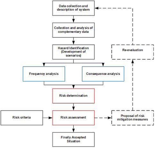
- Good Practice for Risk Assessment Process Flow
The design of safe LNG systems and operations requires the adequate understanding of LNG safety aspects, modelling of accident scenarios, development of safeguards to prevent LNG release, ignition or fire escalation.
Risk Assessment tools will support PAAs in the understanding and the current section includes the elements listed below, in Table 1, considered relevant to assist Port Authorities and Administrations in the context of LNG Risk & Safety aspects, not only from a Comprehensive Guide to Risk Assessment and Process Safety ManagementRisk Assessment perspective but also from on the understanding of LNG safety aspects.
| Table 1. Article Summary table description | ||
|---|---|---|
| Section | Title | Summary Description |
| 8.1 | LNG Risk & Safety Principles | Section including generic risk principles, from an informative perspective. |
| LNG Safety Concepts, Hazards and main factors affecting LNG safety. | ||
| Mechanisms behind LNG hazardous events. | ||
| 8.2 | Risk Assessment in Land Use Planning | Section mostly relevant to those LNG bunkering projects which have been determined within the scope of applicability of SEVESO. |
| Land Use Planning as a tool for major accident prevention. | ||
| Typically relevant for small scale fixed LNG bunkering installations. | ||
| 8.3 | Risk Assessment in LNG Bunkering | Risk Assessment requirements from ISO/TS 18683 By the time this guidance has been published (version “0”), January 2018, the future of ISO/TS 18683 is yet uncertain. Following the publication of ISO20519 both ISO instruments co-exist with several overlapping points (see Section 4.4). Since ISO 20519 does not contain the full depth and scoping for LNG bunkering Risk Assessment as in ISO/TS 18683, it would be very important to ensure that the provisions from the Technical Standard endure for the future. The EMSA Guidance is, however, published in a context of some concern over a possible withdrawal of ISO/TS 18683. Following the situation described above, the EMSA Guidance has taken the route of including part transcriptions and summaries of the provisions in the ISO Technical Standard 18683, instead of drafting a simple reference to an instrument that is very likely to be withdrawn or replaced in the very near future.x summarized. |
| Minimum risk assessment requirements for different LNG bunkering modes. | ||
| Qualitative Risk Assessment/ Quantitative Risk Assessment. | ||
| Minimum Hazard Scenarios. | ||
| 8.3 | Risk Criteria – framework and thresholds | Different types of Risk Criteria for Risk Assessment. |
| ISO/TS 18683 suggested Risk Criteria. | ||
| 8.4 | Risk-based evaluation of Ports Feasibility for LNG bunkering | Section providing guidance elements for Ports willing to define a Technical Specification for the evaluation of LNG bunkering feasibility in the port area. |
| 8.5 | Good practice for Ports on Risk Assessment | Good practice for Ports on LNG bunkering Risk Assessment. |
| Which methodologies to consider for different situations. | ||
| Elements to question and look for when reading/reviewing a risk assessment report. | ||
| Flow diagram with proposed/recommended process map for LNG bunkering risk assessment. | ||
| Independency in Risk Assessment. | ||
LNG Risk & Safety Principles
Hazard and risk
Hazard is a function of the inherent properties of the agent/event in question whereas risk is a function of both the hazard and of the potential likelihood and extent of being exposed to the hazard. In other words, while hazard represents an abstract danger, risk expresses the combination of the level of hazard and the likelihood of its occurrence.
It is the most important relation to retain in all Risk & Safety discussions:
While the two variables are not independent of each other and while the impacts of the hazard depend on preparedness or preventive behaviour (as is the case of natural hazards), the risk must be expressed as a functional relationship rather than a simple multiplication of both variables.
Risk is defined as the product of the probability of occurrence of an accident and its consequence which is usually expressed in terms of lives lost and injuries caused or financial losses suffered.
LNG Safety Concepts
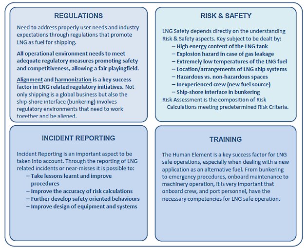
LNG safety is the structured composition of a considerable number of different aspects. All need to be addressed in order to achieve the lowest risk levels. From the technical to the human element, the chain that allows safe and successful operation of LNG (Liquefied Natural Gas) as FuelLNG as fuel for shipping encompasses the following 4 (four) main contributing areas:
Gas carriers have been using LNG as fuel for decades and have established an extremely good safety record. Even though most principles remain the same, using LNG as fuel for conventional ships requires specific adaptations. There is one essential key aspect that makes the real difference. By introducing LNG as fuel to different types of ships, especially those carrying passengers like RO-PAX or cruise ships, the risk calculations, and associated risk mitigation measures need to be adequately addressed.
The development of Regulations and Rules for Vessels to Carry Liquefied Gasinternational regulations, such as the IGF Code, adopted in June 2015, expected to enter in force in January 2017, is fundamental in the establishment of risk based requirements.
Read also: Liquefied Natural Gas Tank Protection
Nonetheless, and because LNG as fuel for shipping is a growing reality, it is always important to be aware of LNG safety first principles and to have always in mind the relevance of all stakeholders.
In order to continue the good safety record, the risks related to both property, and life, have to be minimized. The subject has been identified therefore by all the stakeholders involved in LNG as an alternative fuel for shipping, with safety being addressed at both international and regional/national levels with a continuous developing regulatory frame and published industry guidance and best practices in LNG handling.
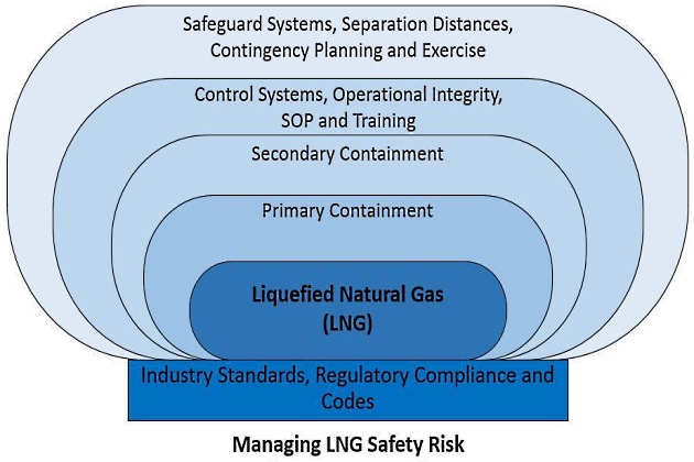
Table 2, below, identifies the main Factors and most relevant possible LNG Hazards, which contribute directly to LNG Safety.
| Table 2. Main Factors in LNG Safety and LNG hazards | |
|---|---|
| Important factors in LNG safety | LNG hazards |
| Fire Hazard Properties of LNG | Fire, deflagration or explosion if in confined space from ignited natural gas vaporising from spilled LNG |
| LNG Physical State reaction | Vapour dispersion and remote flash fire |
| Concentration in air | LNG Leaks |
| Low temperatures of the LNG fuel | Brittle fracture of the steel structure exposed to LNG spills |
| High energy content of the LNG tank | Frost burns from liquid or cold vapour spills |
| Crew Experience and ground staff handling LNG | Asphyxiation from vapour release |
| Over-pressure of transfer systems caused by thermal expansion or vaporization of trapped LNG | |
| Rapid Phase Transformation (RPT) caused by LNG spilled into water | |
| Boiling Liquid Expanding Vapour Explosion (BLEVE) of a pressurized tanks subjected to a fire | |
| Tank over-pressurization due to rollover effects | |
Fire Hazard Properties of LNG
One key aspect that has to be taken into consideration when talking about the fire hazard properties of LNG is that flammability or explosion only occur in very limited physical circumstances. Flammability only occurs when gas volume concentrations are between 5 % and 15 % by volume in a mixture with air, but auto-ignition only occurs at high temperatures. Gas clouds may ignite at the edge if they meet an ignition source as they disperse Explosion, on the other hand, requires gas concentrations within a confined space and, on top, an ignition source. It is not possible to refer to LNG as not being explosive or flammable without giving the exact physical and ambient conditions involved.
Table 3, below, indicates the fire hazard properties of LNG in comparison with other fuels.
| Table 3. Fire hazard properties of LNG in comparison with other fuels | |||||
|---|---|---|---|---|---|
| Properties | Petrol (100 Octane) | Diesel | Methane (LNG) | Propane (LPG) | |
| Flash Point (ºC) | <-40 | >62 | |||
| Flammability in air | Lowest concentration in air (%) | 1.4 | 0.6 | 4.5 | 2.1 |
| Highest concentration in air (%) | 7.6 | 7.5 | 16.5 | 9.5 | |
| Auto-Ignition temperature (ºC) | 246-280 | 250-300 | 537 | 480 | |
Factors of LNG Safety
LNG Physical State reactions
Understanding of LNG physical state is fundamental to predict possible reactions at any stage of the production, transport, delivery and usage stages. LNG is Natural Gas (NG) at cryogenic temperature, brought to -163 °C, just below evaporation temperature of NG (predominantly Methane, CH4).
Development of Natural Gas Liquefaction Cycles based on Energy and Exergy AnalysesLiquefaction of Natural Gas is a key advantage of LNG as it allows transportation and storage at 1/600th the volume it would otherwise take to carry the same amount of NG in the gaseous form.
Production, transportation, distribution and bunkering are only some of the possible operations involved in the life cycle of LNG as fuel for shipping. It is therefore important to understand the behaviour of LNG when pumped, moved and, especially, when different parts of LNG are added in refuelling operation.
Leak and spill prevention is a serious objective in LNG prevention with all technical and operational details of the LNG Cargo Handling Systems and Their OperationsLNG handling operations to be designed towards zero-leakage/zero-release objective.
It will be interesting: Process of Liquefied Natural Gas regasification
In the accidental event of a spill, LNG will immediately vaporize, giving shape to a white cloud of cold LNG vapour that will disperse with the prevailing wind. Should the spill take place into an enclosed space, the evaporated gas will potentially give origin to an explosive atmosphere (if the closed volume reaches the 5-15 % concentration of gas in air).
In case of an LNG release into water, a rapid phase transformation (RPT) will occur. This is a very rapid physical phase transformation of LNG liquid to methane vapour mainly due to submersion in water. RPT does not involve any combustion and cannot be characterised as a detonation. The pressure pulse created by small pockets of LNG that evaporates instantaneously when superheated by mixing in water will travel by the speed of sound and decay as any other pressure pulse. The hazard potential of rapid phase transitions can be severe, but is highly localized within or in the immediate vicinity of the spill area. It will not cause ignition but can be potentially damaging for the ship or equipment. However, RPT is unlikely to damage large structural elements of a ship. The probability of explosion could be limited by a good design of the LNG Bunkering: Technical and Operational AdvisoryLNG bunker Vessel. This means that the vessel should have an open design where confinement is limited, so no significant overpressures can be built up after ignition.
Concentration in Air
As mentioned above, LNG has a flammability range between 5-15 % in volume in air, below this range there is no sufficient fuel (natural gas) for combustion and, above, there is no sufficient oxygen in the mixture for a potential ignition to produce any effect.
From any loss of containment event (spill, release) evaporation will result immediately. Evaporated cold Liquefied Natural Gas and Gas Contractsnatural gas is then a problem that should be regarded differently depending on whether it takes place outside or inside an enclosed space. If the event takes place outside the generation of a white cloud of cold natural gas will lead to a the dispersion of a plume according to the prevailing wind. Flammability range can be reached in the boundaries of the cloud.
If the release leads to the enclosure of gas pockets, either within the structure of the ship or in the port infrastructure, there is the potential creation of an explosive atmosphere. Ship design and port facilities, wherever LNG is handled should take into consideration.
LNG is neither carcinogenic nor toxic. It is an asphyxiant, which dilutes or displaces the oxygen contained in the atmosphere, leading to death by asphyxiation if exposed long enough. Since natural gas in its pure form is colourless and odourless, confined spaces are subject to special attention. With large uncontrolled release quantities, personnel in direct surroundings may be suffering from low oxygen concentrations (<6-15 V %), which should be counteracted by technical and procedural solutions.
Low temperatures of the LNG fuel
LNG is typically stored at a pressure between 1 and 10 bar, whereby the equilibrium temperatures are approximately -160 °C to -120 °C. In order to minimise the risks related to both property and life, it is vital that the material used for the LNG system has been certified for cryogenic temperatures and that the system has built-in pressure relief functionality.
At atmospheric pressure, depending on composition, LNG will boil at approximately -160 degrees Celsius and represent a cryogenic hazard. The cryogenic nature of LNG bunker vessels poses the risk of potentially injurious low temperature exposure of personnel, structural steel, equipment, instrumentation, control and power cabling. Cryogenic exposure of personnel causes frost burns; cryogenic exposure of carbon steel causes embrittlement, possibly resulting in structural failure. Through potential fractures of the hull, following from LNG spills into unprotected structural steel, it is important to note that LNG may penetrate through into enclosed adjacent spaces, leading to potential formation of explosive atmosphere pockets.
High-energy content of the LNG tank
It is vital that the material used for the LNG system has been certified for cryogenic temperatures and that the system has built-in pressure relief functionality. When designing the vessel, deciding where to place the LNG fuel tank and processing equipment, as well as how to arrange the ventilation ducts and pressure relief masts and LNG/gas piping in general, must be well thought through. Access to hazardous areas must be arranged in a safe manner and great effort must be put into developing a complete and consistent safety philosophy from the beginning of any vessel design.
A special type of hazard is a fireball, which is a very rapid combustion process most often associated with a Boiling Liquid Expanding Vapour Explosion (BLEVE). These are only associated with pressurized liquids. The normal mechanism for BLEVE is a pressure vessel containing pressurized liquefied gas (e. g. a pressurized LNG tank) subjected to external fire impingement or catastrophically failing due to other causes. Insulation of a pressurised tank generally contributes to reducing the risk of escalation from impacting fire. Physical barriers prevent direct fire impingement and mechanical impact and reduce the likelihood of a BLEVE. For example, in case an LNG IMO Tanks/Containment SystemsLNG fuel tank is placed below deck, the ship’s hull will act as physical barrier.
Crew Experience and ground staff handling LNG
Inexperience of crew and ground staff can cause wrong handling of LNG and therefore increase the likeliness of hazardous accidents to occur. To avoid hazardous accidents, the planning, design and operation should focus on preventing the release and vapour of LNG. Thereby, factors such as transfer rates, inventories in Piping System of pressure vessels on gas tankershoses and piping, protective systems such as detection systems, ESD and spill protection are essential. The safety philosophy must involve the entire system – from gas bunkering to consumers – and include everything from shutdown functionality to crew awareness.
LNG Hazards
An important part of understanding the table below includes a summary description of the relevant LNG Hazards. They depend not only on the factors described above but also on the design options followed for a given vessel LNG solution.
Figure 2 and 3 present different schematic representations the possible LNG Hazards, depending on the type of release, ignition and confinement.
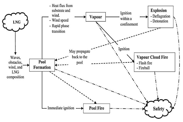
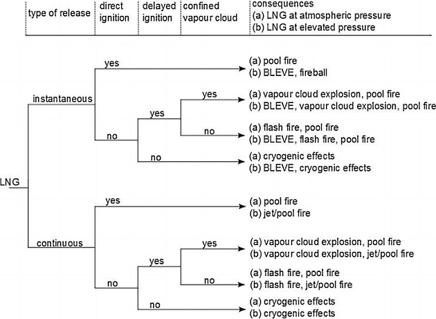
Table 4 details the LNG Hazards.
| Table 4. LNG Hazards | |
|---|---|
| LNG Hazard | Summary Description |
| Flash Fire | A flash fire can occur when a cloud of gas burns without generating any significant overpressure. The LNG cloud can only be ignited where the concentration is above the Lower Flammable Limit (LFL) and below Upper Flammable Limit (ULF). For methane the flammable range is 5 % to 15 % in mixture with air. Below 5 % mix (methane/air) it will be too lean to ignite, and above 15 % it will too saturated to ignite. The gas clouds can only be ignited at the edge as they disperse and meet an ignition source (e. g. open flame, internal combustion engine, sparks). An ignited cloud will “flash back” across all its flammable mass (i. e. that part within the flammable range – between the UFL and LFL). It will then burn at the UFL boundary until the entire gas is consumed. The duration of the flash fire is relatively short, but it may stabilise continuing as a jet fire or pool fire from the leak origin. |
| Pool Fire | For large spills, air cannot transfer enough heat to vaporize much LNG so a part of the spill is likely to end up in a liquid pool. A pool fire may result after a flash fire. A LNG pool fire generates significant thermal radiation with the surface emission power above 200 kW/m2 (a person in protective clothing will typically withstand 12 kW/m for a short time). Once combustion adds to evaporation, the pool will shrink significantly in size to a sustainable pool fire diameter. |
| Jet fire | Jet fires are burning jets of gas or atomised liquid whose shape is dominated by the momentum of the release. Jet fires typically result from gas or condensate releases from high-pressure equipment, e. g. HP pump, high pressure piping etc. Jet fires may also result from releases of high-pressure liquid containing dissolved gas, due to the gas flashing off and turning the liquid into a spray of small droplets. Typical conditions for this are pressure over 2 barg. |
| BLEVE (fire ball) | Fireballs are very rapid combustion processes most often associated with Boiling Liquid Expanding Vapour Explosions (BLEVE) and these are only associated with pressurized liquids. When these are released quickly, the gases flash and this creates extreme speeds and turbulence. This in turn allows a flame front to travel rapidly across the whole flammable envelope. As these releases often do not have much air entrained, the fireball burns across the entire external envelope and causes the flammable mass to rise and radiate large amounts of heat in typically 20 to 40 seconds. |
| Explosion | A vapour cloud explosion can occur when a large flammable mass of hydrocarbon vapour is ignited in a confined space (e. g. an enclosed box). In an open space, outdoors situation, there is no confinement and the experimental evidence is that methane gas will burn relatively slowly with all the expansion resulting in a vertical rise of gas. Within methane clouds, flame propagation is slow. Sufficient flame acceleration to create explosion overpressure will not occur if there not enough congestion or confinement. |
| Asphyxia | Methane, or natural gas, is not toxic. However, in the case of a release of natural gas in an enclosed or semi-enclosed area it can result in asphyxiation due to the lack of oxygen caused by decrease of the partial pressure of oxygen in the inhaled air, which is established when mixing methane and air. Concentrations of 50 % by volume (methane in air) will cause obvious suffocation symptoms like difficulties in breathing and rapid breathing at the same time as the ability to respond deteriorates and muscle coordination weakens. |
| Brittle fracture and cryogenic burns | The cryogenic properties are particular for LNG and it thus require special attention. In order to get the methane into liquid phase it needs to be cooled down below its boiling temperature of – 161 degrees Celsius thus representing thermal hazards to personnel (e. g. in contact with the liquid). However, the extremely low temperatures are not only hazardous to people. While stainless steel will remain ductile, carbon steel and low alloy steel will become brittle and fractures are likely if exposed to such low temperatures. This embrittlement combined with the high thermal induced strains causes a collapse of normal steel structures when get in contact to LNG. Standard ship carbon steel (of all grades) shall therefore be protected and insulated from any possible exposure to an LNG spillage. |
| Rapid Phase Transformati on (RPT) | This is a very rapid physical phase transformation of LNG to vapour mainly due to submersion in water. It can cause a small but serious local physical explosion effect, which at greater distances can cause low overpressures. The risk of RPT is limited to the LNG/water mixing zones. The intensity of explosion will be much less than a detonation (supersonic velocities) and more equivalent to a pressure wave limited to sonic velocity or less. This is unlikely to damage large structural elements of a ship or jetty. No specific modelling is undertaken for RPT as it is unlikely to increase the hazard range of a major spill that has already occurred. Rapid phase changes have not resulted in any known major incidents involving LNG. |
| Overpressure due to Rollover | Rollover is the process of spontaneous mixing up of a similar or two different gaseous cargos due to changes in the density of upper and lower layers level in the tank. This happens because of the boiling off of lighter fractions from the gaseous cargo, resulting in the liquid layer adjacent to the liquid surface to become denser than the layer beneath it. When this situation occurs, stratification develops and the unstable condition relieves itself with spontaneous mixing known as rollover. Tank over pressurization and excessive boil-off leading to emergency venting is the likely consequence of such occurrence. The rollover phenomenon is more likely to occur in large tanks where LNG with different densities is stored. This can result, for instance, from bunkering LNG into a tank which is partially filled with aged liquefied gas. |
| Trapped LNG | If LNG is trapped in the piping or somewhere along the transfer line, a phase transition will cause a local pressure build up. The expansion can potentially cause a pipe burst leading to a significant release of natural gas or LNG depending on the size of the burst and operating conditions. All pipe sections and tanks shall therefore be secured with thermal relief valves. Always take necessary precautions when encompassing system modification or maintenance, as the case of trapped liquid between two valves can lead to fatal consequences (tube cracking). |
Ignition Sources
Table 5, below, includes a comprehensive list of possible ignition sources, with a large scope and variety of typical ignition energies. The different ignition sources should be taken in consideration when assessing LNG fire risk in Hazardous and Safety Zones for LNG bunkering.
| Table 5. Ignition sources | |
|---|---|
| Overview of effective sources of ignition | |
| Source of ignition | Examples of causes |
| Sparks | Mechanically created sparks (e. g., caused by friction, impact or abrasion processes), electric sparks. |
| Arcs | Short circuit, switching operations. |
| Hot surfaces | Heater, metal-cutting, heating up during operation. |
| Flames and hot gases | Combustion reactions, flying sparks during welding. |
| Electrical system | Opening/closing of contacts, loose contact A PELV (U < 50 V) is not an explosion protection measure. Low voltage can still generate sufficient energy to ignite a potentially explosive atmosphere. |
| Static electricity | Discharge of charged, separately arranged conductive parts, as with many plastics, for example. |
| Electrical compensating currents, cathodic anti-corrosion protection | Reverse currents from generators, short circuit to exposed conductive parts/ground fault, induction. |
| Electromagnetic waves in the range of 3 × 10¹¹… 3 × 10¹⁵ Hz | Laser beam for distance measurement, especially for focusing. |
| High frequency 104… 3 × 10¹² Hz | Wireless signals, industrial high-frequency generators for heating, drying or cutting. |
| Lightning strike | Atmospheric weather disturbances. |
| Ionizing radiation | X-ray apparatus, radioactive material, absorption of energy leads to heating up. |
| Ultrasound | Sudden opening of valves. |
| Adiabatic compression and shock waves | Chemical reaction leads to heating up. |
| Exothermal reactions | |
Risk Assessment in Land-Use Planning
NOTE: The text as included in the present Section is adapted from the Study on the completion of an EU framework on LNG-fuelled ships and its relevant fuel provision infrastructure, LOT 1 Final Report, DNV-GL, 2016.
The present section includes Risk Assessment provisions relevant for Land Use Planning, applicable to small scale LNG installations, including in particular those where SEVESO applicability has been determined. Figures 4 to 7, below, are typical installations to which Land-Use Planning (LUP) would be applicable.
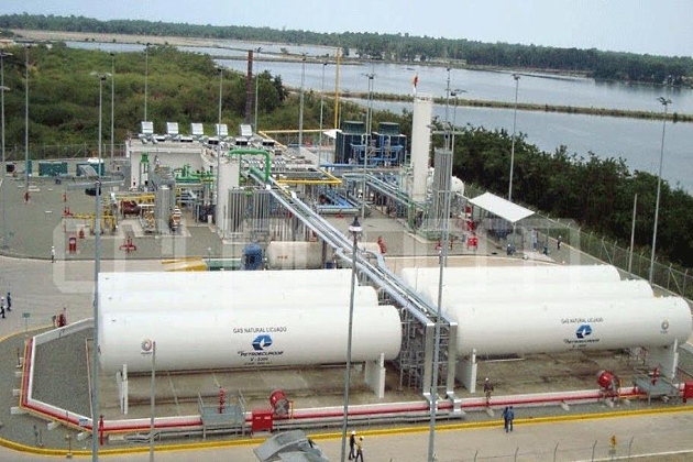
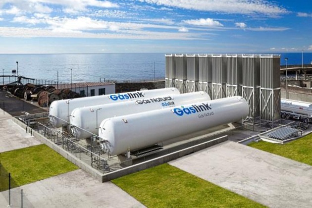
Source: Grupo Sousa Gáslink
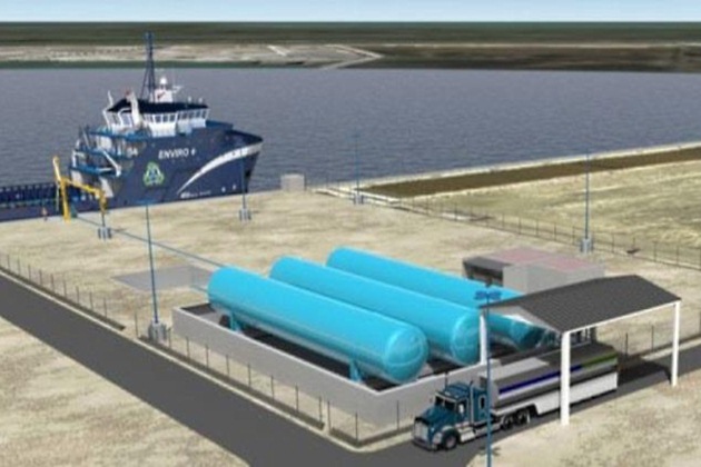
Source: Harvey Gulf
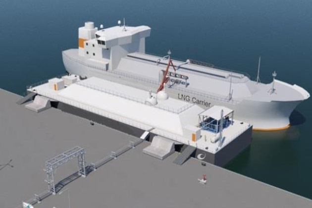
Source: Wartsila
Land-Use Planning – Introduction
Different risk assessment approaches (e. g. quantitative risk assessment: QRA) and regulatory risk acceptance criteria for small scale LNG infrastructure (i. e. primarily those installations that fall under the Seveso directive) are adopted in the different EU countries. Various techniques, methodologies, guidelines and tools used for the general analysis of the risks of activities with hazardous substances were identified. These are commonly used to determine external safety distances between major hazard industrial facilities (or activities) and surrounding land-uses (e. g. vulnerable objects such as residential areas). This process is also commonly known as Land-Use Planning (LUP).
Specific focus is on the different risk assessment approaches and criteria used in EU countries for LUP as per the national legislative implementation of the Seveso directive and to illustrate which (parts of) approaches and criteria have specific or general applicability.
Read also: Gas Heaters on Liquefied Natural Gas Carriers
Background information is provided on the various existing methodological approaches. In particular, the QRA approach is elaborated by describing its generic methodology, required tools and available guidelines for the risk analysis. With respect to guidelines, attention is given to industry best practices that supersede national or local regulations, e. g. global QRA best practices and methodologies used by major oil & gas companies or advisory companies.
Furthermore, many countries have established risk criteria for regulatory purposes. These are essential to assess the risk in a QRA (i. e. to determine whether the risks are acceptable or can be considered tolerable). For this reason, the generic framework for risk criteria and the principles of (risk) threshold criteria are explained in more detail.
Next to the use of a QRA approach in LUP, various other potential applications of a QRA are discussed for the safe and secure operation of Small Scale LNG infrastructure or activities:
- Assessment of specific risks and mitigating measures for Simultaneous Operations.
- Determination of safety zones.
- Determination of internal safety distances (i. e. to prevent cascading effects).
Finally, based on the identified issues, concrete suggestions for harmonization of and improvements for risk assessment approaches (including methodologies, guidelines, tools and risk criteria) used for LNG small scale infrastructure and activities across Europeans port are provided.
The structure of this section is as follows:
- An overview of existing (categories of) methodological approaches used for LUP is provided in section “Methodological approaches”. The main principles and differences are explained. The QRA approach is only one of the approaches used for LUP;
- Section “QRA methodology” describes the generic methodology of a QRA approach, followed by an overview of leading consequence and QRA software tools required for a QRA (“Consequence and risk analysis software tools”) and QRA guidelines and best practices;
- A framework for risk criteria and principles of (risk) threshold criteria are detailed in paragraph “Risk criteria – framework and thresholds”.
Methodological approaches
Existing methodological approaches for land-use planning in European countries have been summarized and described in literature. In general, the existing methodologies can be divided into the following four categories:
Consequence-based approaches
The consequence-based approach is based on the assessment of consequences of credible (or conceivable) accidents, without explicitly quantifying the likelihood of these accidents. The consequences of the accidents are mostly taken into consideration by calculating the distance in which the physical and/or human health impacts (e. g. heat radiation) reach, for a given exposure period and a threshold value (e. g. irreversible health effect/harm or fatality). The external safety zone is thus defined according to which LUP restriction is applied. The method has been generally used in Luxembourg and Austria.
Deterministic approach with implicit judgment of risk
A simplified form of the consequence-based approach is the use of “generic” separation distances.
These distances are usually derived from selected scenarios and developed on a conservative basis. In their most simple form, they are derived from expert judgement, including consideration of historical data or experience from operation similar plants. The approach of generic separation distances has been established and used in Germany.
Risk-based (or “probabilistic”) approaches (i. e. QRA)
The risk-based approaches define the risk as a combination of the consequences derived from a range of possible accidents, and the likelihood of the accidents. The results are represented as individual risk and/or societal risk. LUP criteria are based on specific acceptability criteria with respect to the calculated risk. In general, the approach is similar to the QRA methodology described in the next paragraph. This approach is followed in e. g. the United Kingdom, Belgium (Flanders) and the Netherlands.
Hybrid approaches
Hybrid approaches (or semi-quantitative) combining risk and consequence-based approached have been developed and extensively used in France and Italy. Under these methods, one of the elements (usually frequency) is assessed more qualitatively, i. e. using classes rather than continuous figures. The use of a risk matrix is a typical example. For instance, France adopted a hybrid approach that combines a consequence-based approach for the determination of the zones that correspond to damage thresholds and a risk-based approach for the determination of the considered accident scenarios.
Respectively, Italy has adopted a hybrid criterion that takes into account the frequencies, as mitigation factor for the damaged zones, identified using a consequence-oriented approach.
It will be interesting: Fundamentals of Liquefied Natural Gas
The above described approaches often require the use of risk tools as described in paragraph “Consequence and risk analysis software tools”. Next to these tools, (risk) threshold criteria are needed to determine the extent of the external safety zone in LUP (see “Risk criteria – framework and thresholds”).
QRA methodology
A quantitative risk assessment is a well-known and widely accepted methodology to quantify safety risks. It is an approach to determine risk levels associated with accidental Loss of Containment events (e. g. spills, gas releases).
A QRA can give insight into the risks to human life or property of a certain activity by calculating the potential hazardous effects of a variety of scenarios as well as considering the probability of occurrence of these scenarios.
Typical objectives of a QRA study are:
- Quantify the level of safety risks (to people or property) associated with the operation of a plant or activity with hazardous materials.
- Demonstrate that the levels of risks are in compliance with risk acceptance criteria as agreed with authorities.
- Evaluate and select safeguards and risk reducing measures, if needed.
In general, a QRA tries to answer five simple questions. Beside each question, the technical term is listed for that activity in the risk assessment process:
| 1 | What can go wrong? | Hazard Identification |
| 2 | How bad? | Consequence Modelling |
| 3 | How often? | Frequency Estimation |
| 4 | So What? | Risk Assessment |
| 5 | What do I do? | Risk Management |
The QRA activities are explained in more detail underneath.
Hazard identification (What can go wrong?)
The first part of the quantitative risk assessment is similar to the qualitative risk assessment, i. e. to establish the study basis and perform a Hazard Identification Session (HAZID) to identify and screen potential hazardous situations. Hazards of LNG and Relevant GasesPotential hazards to people or property can arise if a loss of containment occurs. A comprehensive identification of potential hazardous scenarios is critical. Typical accident and loss of containment scenarios based on historical incident data can be assessed on relevance and should be complemented with the outcomes of a site specific HAZID.
The current industry practice is to perform a HAZID for LNG activities, especially in case of special circumstances where the risks are not fully known, such as SIMOPS (see also section How to Conduct Simultaneous Operations during LNG Bunkering“Simultaneous Operations”) or in case of e. g. non-standard LNG bunkering scenarios. Some authorities also request a HAZID to be carried out as part of the permitting process, despite the fact that this is normally not specifically mandated in legislation.
Read also: Regulations and Guidance for Liquefied Natural Gas Shipping
Risk assessment guidelines may also prescribe accident scenarios for failure of various equipment types and piping based on historical incident data. These are, however, not LNG-specific. The ISO/DTS 16901 specifies types of accident scenarios to be considered for LNG import/export terminals. The specifics of the given accident scenarios (e. g. release size and associated base frequencies) are however not provided. There is a need for a complete and detailed definition of credible accident scenarios that can occur during the operation of Small Scale LNG installations and activities. It must be noted that there are currently developments Projects and developments such as: Dutch Safety Program, LNG-specific risk calculation guidelines, research into failure frequencies for LNG equipment.x in the Netherlands with the purpose to fill this knowledge gap (reference is made to paragraph “Risk assessment guidelines and best practices” for more information).
Consequence Modelling – (How bad?)
In parallel with the frequency analysis, consequence modelling evaluates the resulting effects if the accidents occur, and their impact on people and property. Ignited flammable releases can result in various consequences such as jet-, pool, – or flash fire, fireball or vapour cloud explosions depending on the type of scenario and time and place of ignition. The consequence assessment shall be carried out using recognized consequence modelling tools that are capable of determining the resulting effects and their impact on personnel, equipment and structures. These tools are normally validated by experimental test data appropriate for the size and conditions of the hazard to be evaluated.
Reference is made to paragraph “Consequence and risk analysis software tools” for more information regarding leading consequence and risk assessment tools and their suitability to quantify consequences or risks of potential accidents occurring in LNG installations or during activities.
Failure frequencies – (How often?)
After the hazards of a system or activity have been identified, the next step in performing the QRA is to estimate the frequency at which the hazardous events (or scenarios) may occur. The following are common techniques and tools available for frequency assessment:
- Analysis of historical incident data;
- Fault tree analysis;
- Event tree analysis;
- Simulations.
The selected technique will depend on the availability of historic data and statistics.
There are a few sources of data for failure frequency data for process equipment loss of containment: Netherlands and Belgium have issued two different onshore frequency datasets for use in Seveso Directive risk assessments, and some companies and consultants have their own data. It must also be stressed that nominated frequencies are tightly integrated with national risk criteria. Unfortunately, there are currently no LNG specific failure frequencies due to the lack of available incident data. Risk analysts are forced to use release frequency data from generic sources. DNV GL recommends using data from the hydrocarbon from the Hydrocarbon Release Database (HCRD) from the UK HSE, which are based on historical data from oil platforms in the North Sea and are representative for equipment used in those installations. This is considered the most extensive dataset of its type and superior to current published datasets, which often have much smaller and older data which do not reflect current integrity management programs. The data forms the basis for onshore and offshore QRA’s which, in the absence of LNG specific data, is also used in QRAs for LNG installations. There is currently no statistically sound basis for modifying the source failure data from the HCRD (or any other dataset for that matter) to account for onshore and cryogenic or LNG specific applications.

Source: Pixabay.com
There is, however, a strong believe among owners and designers of LNG equipment that release frequencies from LNG-specific equipment and piping should have lower values than those from their equivalent in offshore platforms. Therefore, QRA results based on HCRD release frequencies are believed to be conservative for LNG applications. It is unknown to what extent this conservatism could potentially drive the calculated risk of LNG installations to high, thus requiring the implementation of (expensive) risk reduction measures or require large external safety distances.
Risk Assessment – (So What?)
The next stage is to introduce criteria which are yardsticks to indicate whether the risks are “acceptable“, “tolerable” or “negligible” or to make some other value-judgment about their significance.
The most common criteria used in the industry for risk assessments when relating risk to people are individual and societal risk criteria (reference is made to section “Threshold criteria” for more details). This step begins to introduce non-technical issues of risk acceptability and decision making, and the process is then known as risk assessment.
Risk Management – (What to do?)
In order to make the risks acceptable, risk reduction measures may be necessary. The benefits from these measures can be evaluated by recalculating the risk. Investigation of risk mitigation measures and their impact on the calculated risk can also be performed to demonstrate that the residual risk is As Low as Reasonably Practical (ALARP). For a risk to be ALARP it must be possible to demonstrate that the cost involved in reducing the risk further would be grossly disproportionate to the benefit gained (see also “Generic framework for risk criteria”).
Consequence and risk analysis software tools
A comprehensive overview of leading software tools for undertaking consequence and risk (e. g. QRA) analysis is published in a paper by the American Society of Safety Engineers. The key findings of this paper where that there is no single “best” consequence tool. What is important is the selection of the appropriate tool for the specific situation being modelled, i. e. the tool should be proportionate to the magnitude of the hazard.
In addition, it is important that the software models are periodically maintained, verified and validated in order to establish that accurate results are generated. Model validation for LNG releases is of particular importance. For instance, an LNG release often results in heavy gas dispersion behaviour despite the fact that methane is lighter than air. This mechanism is difficult to model and therefore the dispersion model should be properly validated to ensure that accurate results are predicted.
Risk assessment guidelines and best practices
Various guidelines and best practices to perform risk assessments (i. e. QRA) exist. The purpose of this paragraph is to outline and describe the main publications and to discuss LNG applicability in particular.
It is not the intention to provide an exhaustive list. Various guidelines and best practices are published by e. g. the following entities and are more detailed below:
- National authorities (e. g. UK HSE, National Institute for Public Health and the Environment, (RIVM, the Netherlands)).
- Major oil and gas companies.
- Advisory companies (e. g. DNV GL, Bureau Veritas).
- International guidelines (e. g. ISO).
National authorities
In countries that set requirement for a QRA, rather detailed information is needed for the design of the LNG small scale supply chain installations, the possible failure scenario’s, the frequency of occurrence, the release consequences and how to model all these items. Not all countries are in that respect prescriptive (i. e. no specific guidelines are mandated). For instance, the Netherlands prescribe complete guidelines (and software tools) to be used to execute QRA’s. Belgium (Flanders) mandates only the use of specific failure frequencies, but not the use of specific software tools and accompanying model parameters. The UK HSE, on the other hand, provides only guidance on the evaluation of risk and risk tolerability (e. g. ALARP demonstrations), rather than the definition of failure cases, failure frequencies and how to model the latter. No specific onshore risk assessment guidelines are currently mandated (or published for that matter) by the UK HSE.
Read also: Liquefied Natural Gas Fundamental Knowledge and Understanding
The most well-known and world-wide accepted guideline for the execution of quantitative risk assessment is the “purple book“. Together with the other “coloured books” (yellow, green and red) the guideline forms valuable reference material for safety studies. The books are written by Dutch Government (RIVM) with support from the research institute TNO. The coloured books have become obsolete and are not kept up-to-date anymore since 2005. The successor is the Dutch Reference Manual Risk Assessments Bevi, which is mandated in the Netherlands for the execution of QRA’s (see also Assessing the Safety Risks of LNG Bunkering“Risk-based evaluation of Ports Feasibility for LNG Bunkering”). Although these guidelines are not specifically written for LNG, they have generic applicability. However, the main limitation is that they do not specify LNG-specific failure frequencies. Therefore, the RIVM has recently initiated a project (start-up phase) into LNG-specific failure frequencies for LNG transfer systems and stationary (double walled) pressure vessels. This project is part of a larger two-yearly (national) LNG safety research program with the purpose to enhance and accelerate full development of LNG safety issues including the determination of external safety distances used in LUP. The LNG Safety Program has started in the beginning of 2014 and is carried out as a joint cooperation between public and private stakeholders. The two-year (2014-2015) program has been initiated by the National (Dutch) LNG Platform after numerous requests from market parties and Dutch emergency response organisations to enhance and accelerate full development of LNG safety issues.x
Furthermore, separate guidelines have been developed by the RIVM for risk assessments of specific (LNG) installations. A similar guideline for LNG bunker stations is currently under development (final stage). These guidelines also contain case studies.
International guidelines
An LNG-specific risk assessment guideline is recently published by the International Organization for Standardization. This is the ISO/DTS 16901 (OGP 116901) – Guidance on performing risk assessment in the design of onshore LNG installations including the Ship/Shore interface.
LNG Bunkering Risk Assessment
References
The following references were considered in particular for the present Section:
- ISO/TS 18683:2015. (15-Jan. 2015). Guidelines for systems and installations for supply of LNG as fuel to ships. Technical Specification.
- ISO/DIS 20519:2016. Ships and marine technology – Specification for bunkering of gas fuelled ships. (Draft International Standard).
- LNG Bunkering Guidelines IACS Recommendation n. 142, on LNG Bunkering, IACS, 2016.
- Society for Gas as a Marine Fuel (SGMF) (2017) – Gas as a marine fuel, safety guidelines, Bunkering Version 2.0, February 2015.
- DNVGL-RP-G105 Edition October 2015 – Development and operation of liquefied natural gas bunkering facilities, Recommended Practice, DNV GL, 2015.
Introduction
The present Section includes references and elements strictly relevant to LNG Bunkering Risk Assessment, highlighting the provisions from ISO/TS 18683 and ISO 20519.
A bunkering operations risk assessment should be undertaken in accordance with ISO/TS 18683. This technical specification is specific to the supply of LNG as fuel to ships and refers to recognised standards that provide detailed guidance on the use and application of risk assessment. The objectives of the bunkering operations risk assessment are to:
- Demonstrate that risks to people and the environment have been eliminated where possible, and if not, mitigated as necessary;
- and Provide insight and information to help set the required safety zone and security zone around the bunkering operation.
In order to meet these objectives, as a minimum, the bunkering operations risk assessment should cover the following operations:
- Preparations before and on ship’s arrival, approach and mooring.
- Preparation, testing and connection of equipment.
- LNG transfer and boil-off gas (BOG) management.
- Completion of bunker transfer and disconnection of equipment.
- Simultaneous operations (SIMOPS).
Following the above Following the indication of ISO/TS 18683 the risk assessment shall be carried out in agreement with recognized standards, such as ISO 31010, ISO 17776 and ISO 16901.
Read also: Features and Functions of Integrated Alarm System
ISO/TS 18683 indicates already an important point which anticipates one of the most important good practice notes in terms of Risk Assessment: The risk analysis shall be carried out with a team ensuring an objective and independent assessment. This is an important aspect of Risk Assessment requirements as outlined in ISO/TS 18683, bringing the concept of “independency” of risk assessment process.
Source: Pixabay.com
ISO/TS 18683 indicates, as a minimum, a qualitative risk assessment to be carried out for The Role of LNG Bunkering Infrastructurebunkering installations complying with the defined standard bunkering scenarios as defined in ISO/TS 18683 (TTS, PTS or STS). A note is however made in section “Risk Assessment Methodologies” where standard LNG bunkering modes would still very likely require a QRA to be conducted, leading the requirement above the minimum framework defined by ISO/TS 18683.
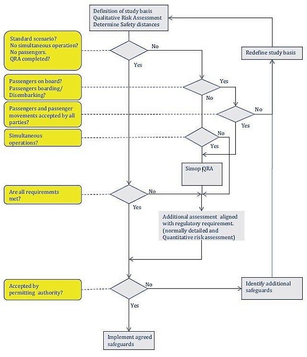
For bunkering installations deviating from the standard bunkering scenarios Standard bunkering is characterised by three bunkering scenarios, as noted in ISO/TS 18683: 1. PTS (Port/Shore-to-ship); 2. TTS (Truck-to-Ship); 3. STS (Ship-to-Ship).x defined in ISO/TS 18683 or not meeting all requirements, the qualitative risk assessment shall be supplemented by a detailed assessment of the deviations as agreed with the regulator. Normally, this includes a comprehensive quantitative risk assessment to demonstrate that the overall acceptance criteria are met and that implemented safeguards compensate for not meeting all requirements.
The schematic approach is illustrated in Figure 9, extracted from ISO/TS 18683.
Qualitative risk assessment (QualRA)
Contents
A qualitative risk assessment for a LNG bunkering project/operation shall, as a minimum, comprise of the following elements, as described in ISO/TS 18683:
a SCOPE: Definition of study basis and familiarization with the design and planned operation of the bunkering facility;
b HAZID: HAZID review with the purpose of identifying hazards and assess the risks using a risk matrix. The HAZID shall also identify risk reducing measures for all hazards representing medium or high risks. The HAZID should consider accidental spills and consider/identify technical and operational safeguards. The HAZID shall also determine maximum credible release scenarios as a basis for the determination of the safety zones;
cSAFETY ZONE: Determination of safety zones and security zones (these may later be revised with reference to QRA);
d REPORT: Reporting.
The qualitative risk assessment shall consider all possible bunkering configurations reflecting the variety of ships to be bunkered.
Scope
As adapted from ISO/TS 18683 below the scoping basis is defined where a minimum sample the relevant elements are listed, for consideration:
a Description and layout of the bunkering installation, including all Concept Project drawings and intended receiving ship’s characteristics;
b All technological elements envisaged for safety control (such as alarms or other relevant features);
c Description of other simultaneous activities and stakeholders and third parties in the area;
d Description of all systems, components with regard to function, design, and operational procedures and relevant operational experience;
e Description of operations and operational limitations;
f Organization of the bunkering activities with clear definitions of roles and responsibilities for the ship crew and bunkering personnel;
g Identification of authority stakeholders;
h Acceptance criteria for the project aligned with authority requirements, in which the risk matrix shown in Annex A represents example of minimum requirements with respect to risk to personnel.
Methodology
The QualRA methodology is strongly based on the HAZID (its core part), following an initial scoping basis, and finalizing with the adequate screening of the LNG bunkering hazardous situations. The HAZID Methodology is outlined in the following section, using ISO/TS 18683 as reference.
HAZID
Table 6, below, outlines the structure and contents of the HAZID as the core part of the Qualitative Risk Assessment.
| Table 6. HAZID Methodology (ISO/TS 18683) | ||||
|---|---|---|---|---|
| Part | Description/Details | |||
| General | workshop meeting with a multi-discipline team using a structured brainstorming technique based on a checklist of potential HSE issues; | |||
| means of identifying, describing, and assessing HSE hazards and threats at the earliest practicable stage of a development, and; | ||||
| Rapid identification and description process only. | ||||
| HAZID team | The HAZID team shall involve a facilitator supported by experienced representatives from different disciplines. The following disciplines shall be represented: | LNG operational experience; | ||
| marine expertise; | ||||
| bunkering experience; | ||||
| local knowledge; | ||||
| other specialist should be available “on call”; | ||||
| familiarity with risk assessment techniques for LNG facilities including assessment of dispersion, fire, and explosion | ||||
| The HAZID team shall be selected to ensure objective and independent assessment. | ||||
| As good practice PAAs should always be represented in HAZID workshops for prospective LNG bunkering projects within their ports. Before participation in HAZID Workshops PAA participants should be able to contribute with Port specific information that may be of assistance to safety discussions. | ||||
| Examples of such information: | Tidal information | |||
| Local known weather effects | ||||
| Operational restrictions | ||||
| Multi-operator information | ||||
| Berthing information | ||||
| Workshop methodology | Identify potentially hazardous events. | |||
| Assess these events with regard to consequence and likelihood and rank the risks. The process of risk ranking is normally performed using a risk matrix. | ||||
| Identify and assess potential risk-reducing measures. | ||||
| dentify hazards and safeguards that need to be followed up later in the project. | ||||
| Identify maximum credible accidental release (i. e. release scenarios that shall be the basis for definition of the safety zones). | ||||
| Identify need for PPE for the personnel involved in the operation. | ||||
| Hazardous events | The HAZID shall, as a minimum, consider the following hazardous events: | 1. LNG releases: | a. failure of QC/DC or ERC equipment; | |
| b. hose or loading arm failure due to the following: | i. design flaws; | |||
| ii. wear, tear, and fatigue; | ||||
| iii. excessive loads due to dropped objects or collision and impacts from ships or trucks; | ||||
| iv. ships mooring failure; | ||||
| v. unplanned movement of the truck; | ||||
| c. pressure surge in transfer lines; | ||||
| d. releases from piping systems; | ||||
| e. incorrectly planned or performed maintenance; | ||||
| f. incorrect operational procedures including the following: | i. cooling down; | |||
| ii. connection; | ||||
| g. failure to detect releases masked by mist and fog due to cold surfaces; | ||||
| h. failure to detect releases at low level due to location of gas and leak detectors; | ||||
| i. over-filling and over-pressurization of ships bunker tanks (e. g. by flashing, incorrect bunker rate, or bunkering procedure); | ||||
| j. over-pressure of transfer systems caused by thermal expansion or vaporization of trapped LNG; | ||||
| k. possible rollover in bunker tanks caused by loading LNG of different densities; | ||||
| 2. ignition sources: | a. electrical hazards; | |||
| b. other ignition sources; | ||||
| c. activities inside the safety zone; | ||||
| d. gas dispersion beyond the safety zone; | ||||
| 3. release of nitrogen, asphyxiation; | ||||
| 4. Events caused by human error. | ||||
| Hazardous effects | Hazardous effects following the initial events shall be considered. These shall include the following: | 1. fire hazards: | a. structural failure and escalation due to high temperatures; | |
| b. injuries to personnel; | ||||
| c. damage to equipment; | ||||
| d. ignition of secondary fires; | ||||
| e. potential BLEVE of pressurized LNG containment subjected to a fire; | ||||
| 2. possible vapour cloud deflagration/flash fires: | a. damage to equipment and escalation; | |||
| b. injury to personnel; | ||||
| c. damage to fire-fighting equipment and safeguards; | ||||
| 3. cryogenic hazards: | a. structural failures including brittle fracture of the steel structure exposed to LNG spills; | |||
| b. frostbite from liquid or cold vapour spills; | ||||
| 4. other hazards: | a. asphyxiation; | |||
| b. Possible rapid phase transition caused by LNG spilled into water. | ||||
| Hazardous effects | Action plan: | a) The HAZID shall produce a list of hazards, ranked with respect to consequence and likelihood | ||
| b) Recommendations for risk reducing measures and an action plan for follow up. | ||||
| c) Safeguards to be considered in the HAZID should, as a minimum, include the following: | a) training of involved personnel; | |||
| b) maintenance planning; | ||||
| c) cryogenic spill protection; | ||||
| d) personal protective equipment for operators; | ||||
| e) evacuation plans; | ||||
| f) fire-fighting equipment; | ||||
| g) shore to ship and ship to ship communication plan; | ||||
| h) Elimination or minimization of ignition sources, including the use of isolation elements. | ||||
| d) The action plan addresses each recommendation developed along the HAZID meeting and shall be; | ||||
| e) Followed up for its assessment and implementation. Meeting records. | ||||
| Meeting records | A typical HAZID workshop is normally recorded with the following: | a) activity ID; | ||
| b) function; | ||||
| c) system failure effect; | ||||
| d) consequence category (environment, people, cost, reputation); | ||||
| e) consequence (ranked according to risk matrix being used); | ||||
| f) likelihood (ranked according to risk matrix being used); | ||||
| g) criticality (low, medium, or high); | ||||
| h) action items identified; | ||||
| i) Comments. | ||||
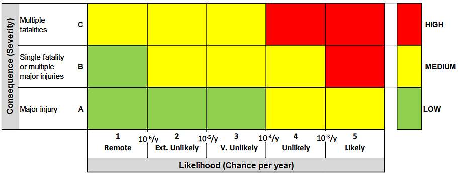
| Risk Matrix | The risk matrix is an effective tool for qualitative risk assessment and screening. It is normally used in workshops in support of HAZIDs and FMEA. It can be used to identify hazards that shall be further investigated in the subsequent quantitative analysis. | |||
| The Risk Matrix allows in particular | ||||
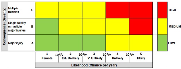
| The results from the detailed analysis in terms of frequency and consequences can be reported in the matrix. This enables to track and tune the efficiency of the risk reducing measures, qualify initial assumptions, and confirm the initial scenario ranking. ISO/TS 18683 contains a Risk Matrix, with risk ranking categories that can be used unless, at national level, other frame is applicable. (See fig. 10) | ||||
| Consequence Category | A. Major injury – long-term disability/health effect | |||
| B. Single fatality or multiple major injuries – one death or multiple individuals suffering long-term disability/health effects | ||||
| C. Multiple fatalities – two or more deaths | ||||
| Likelihood Category | 1. Remote – 1 in a million or less per year | |||
| 2. Extremely Unlikely – between 1 in a million and 1 in 100 000 per year | ||||
| 3. Very Unlikely – between 1 in 100 000 and 1 in 10 000 per year | ||||
| 4. Unlikely – between 1 in 10 000 and 1 in 1 000 per year | ||||
| 5. Likely – between 1 in 1 000 and 1 in 100 per year | ||||
| The likelihood categories can be related to a ship life. For example, assuming a ship lifetime is 25 years, then for a scenario with an annual likelihood of 1 in a million (i. e. rating 1 Remote) the probability of occurrence in the ship’s lifetime is 1 in 40 000 (i. e. 1/(10-6 × 25)). | ||||
| Risk Rating and Risk Criteria Guidance (referring to figure 13) | Low Risk – A1, A2, A3 & B1 | The risk can be accepted as “mitigated as necessary”. Where practical and cost-effective it is good practice to implement mitigation measures that would further reduce the risk. | ||
| Medium Risk – A4, A5, B2, B3, B4, C1, C2 & C3 | The risk is tolerable and considered “mitigated as necessary”. This assumes implementation of all reasonably practicable mitigation measures. | |||
| High Risk – B5, C4 & C5 | The risk is unacceptable and is not “mitigated as necessary”. Additional or alternative mitigation measures must be identified and implemented before operation, and these must reduce the risk to medium or low. Mitigated as necessary: This is the wording used within the IGF Code and is akin to the phrase “As Low As Reasonably Practicable”, commonly referred to as ALARP. | |||
| Safety Zone | The work towards the determination of the Safety distance can be part of the HAZID Workshop. The determination of the Safety Zone, however, should be initiated as an analytical process, based on a maximum release scenario. | |||
| Should a “maximum release scenario” produce impracticable Safety Zones it would be possible to establish, in the context of the HAZID workshop, a risk based re-evaluation and, collectively, determine a credible release scenario that could be used for that purpose. | ||||
| The release scenario to be considered should be identified in the HAZID reflecting the project specific factors such as the following: | transfer rates and inventory in the bunkering facilities; | |||
| operational modes; | ||||
| implemented safeguards; | ||||
| Properties of the LNG in the bunkering system (temperature, pressure). | ||||
| See also article LNG Bunkering Hazardous Zone: Safety, Classification, and Control“Control Zones” | ||||
| Security Zone | Findings from the HAZID should also contribute to provide input to the determination of the Security Zone. | |||
| See also article LNG Bunkering Hazardous Zone: Safety, Classification, and Control“Control Zones” | ||||
| Reporting | The HAZID Report will be an important part of the Risk Assessment Report and should be subject to Approval by the PAA. | |||
| For projects to which Seveso applicability has been determined the Risk assessment shall be part of the Safety Report (Upper-Tier) and submitted to the competent authority and to the PAA. (see article “Regulatory Frame Best Practice – Applicability in the Bunkering InterfaceSeveso III Directive – Major Accident Prevention Directive“) | ||||
| The minimum information indicated in ISO/TS 18683 should be: | a. study basis including description of design, operations, and assumptions being made; | |||
| b. description of the working process including participants in the workshops; | ||||
| c. summary of the identified hazards and the risk assessment; | ||||
| d. release scenario to serve as a basis for determination of the safety zone; | ||||
| e. determined safety distances; | ||||
| f. definition of the security zones; | ||||
| g. summary of follow up actions; | ||||
| h. Detailed records from the workshop. | ||||
Report
The HAZID Report will be an important part of the Risk Assessment Report and should be subject to Approval by the PAA.
For projects to which Seveso applicability has been determined the Risk assessment shall be part of the Safety Report (Upper-Tier) and submitted to the competent authority and to the PAA. (See article “Regulatory Frame Best Practice -Applicability in the Bunkering InterfaceSeveso III Directive – Major Accident Prevention Directive“)
The minimum information to be contained in the Report, as adapted72 from ISO/TS 18683 should be:
a Study basis including description of design, operations, and assumptions being made;
b Description of the working process including participants in the workshops;
c Summary of the identified hazards and the risk assessment;
d Identification of the Risk Matrices with the full risk screening developed in the HAZID;
e Clarification on the risk ranking categories used;
f Release scenario to serve as a basis for determination of the safety zone (maximum or credible release scenario;
g Determined safety distances;
h Definition of the security zones;
i Summary of follow up actions;
g Detailed records from the workshop.
Quantitative risk assessment (QRA)
Contents
In addition to the QualRA, a Quantitative Risk Assessment (QRA) is recommended when:
- Bunkering is not of a standard type (PTS, TTS or STS, in simple standard configuration, as defined in ISO/TS 18683);
- Design, arrangements and operations differ from the guidance given in ISO/TS 18683 or IACS Rec.142;
- Simultaneous Operations (SIMOPS) are planned to take place along with LNG bunkering.
- Automation elements are introduced to significantly reduce human intervention in operations (linked to system analysis).
- A reduction in a Safety Zone is intended, on the basis of consequence/ probabilistic data for the specific LNG bunkering location.
- Whenever a numerical calculation of Risk is required for verification of any given Risk Criteria.
The requirement for a QRA (in addition to a QualRA) is normally determined by the Administration or Port Authority based on the conclusions and outcomes of the QualRA and accepted by the concerned parties.
A quantitative risk assessment for a LNG bunkering project/operation shall, as a minimum, comprise of the following elements (most of them coincident with the QualRA.
e SCOPE: Definition of study basis and familiarization with the design and planned operation of the bunkering facility
f HAZID: HAZID review with the purpose of identifying hazards and assess the risks using a risk matrix. The HAZID shall also identify risk reducing measures for all hazards representing medium or high risks. The HAZID should consider accidental spills and consider/identify technical and operational safeguards. The HAZID shall also determine maximum credible release scenarios as a basis for the determination of the safety zones;
g CRITICAL HAZARDS for Modelling and Risk Analysis (Taken from Critical HAZID scenarios);
h SAFETY ZONE: Determination of safety zones (as derived from curves for LNG vapour dispersion, individual risk, societal risk, thermal radiation, explosion pressure. Typical curves to set QRA safety distances would be IR – Individual Risk and FN – Societal Risk curves);
i REPORT: Reporting.
The qualitative risk assessment shall consider all possible bunkering configurations reflecting the variety of ships to be bunkered.
Methodology
Described in “QRA methodology”.
Report
QRA Report should contain all elements listed in “Report” above and, in addition:
a Identification of the most critical scenarios;
b Approach followed.
c Software used for consequence modelling.
d Identification and experience of the analyst, including evidence of company-specific validation procedures.
e Assumptions used for modelling.
f Simplifications used in computational model.
g Probability data.
h Software used for any probability event failure scenarios calculation.
i Risk Calculations.
j Risk contours in adequate aerial images for the area of interest
k Identification of any operation-specific elements taken into consideration for the modelling.
l Safeguards considered and due justification for any risk attenuation which hasn’t either derived from.
HAZOP
The risk assessment activities will be broken into two main parts, a higher level HAZID, included in the context of a QualRA/QRA activity, followed by a more detailed HAZOP. It is recommended that both of are conducted with professional guidance to ensure an appropriately detailed risk assessment outcome is achieved.
A hazard and operability study (HAZOP) is a structured and systematic examination of a complex planned or existing process or operation in order to identify and evaluate problems that may represent risks to personnel or equipment.
Read also: Exploring Propulsion Systems and Turbo Alternators on Liquefied Gas Carriers
The intention of performing a HAZOP, in the specific context of LNG Bunkering, is to review the design to pick up design and engineering issues that may otherwise not have been found. The technique is based on breaking the overall complex design of the process (LNG bunkering system or operation) into a number of simpler sections called “nodes” which are then individually reviewed. It is carried out by a suitably experienced multi-disciplinary team (HAZOP) during a series of meetings.
The HAZOP technique is qualitative, and aims to stimulate the imagination of participants to identify potential hazards and operability problems. Structure and direction are given to the review process by applying standardized guide-word prompts to the review of each node.
Guidance for conducting a HAZOP for LNG bunkering operation is detailed in the Annex of IACS Rec.142.
Risk criteria – framework and thresholds
Generically it is important to note that there will only be a “Risk Assessment” if Risk Criteria is available and agreed that allows it use to evaluate calculated risk figures.
Both in Qualitative and Quantitative Risk Assessments risk criteria must be in place that allows the evaluation and approval of a given Risk Evaluation Study. It can then be called a Risk “Assessment“, following the exercised of risk ranking through the.
Generic framework for risk criteria
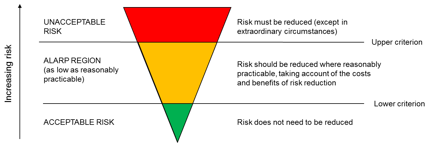
A framework for risk criteria can be either two or three bands. The simplest framework for risk criteria is a single risk level which divides tolerable risks from intolerable ones (i. e. acceptable activities from unacceptable ones. This framework is based on two bands (implies a single risk criterion).
Another approach is to use two criteria; dividing risks into three bands:
- The upper band is where the risk are usually considered intolerable whatever benefits the activity may bring, and risk reduction measures are essential whatever their cost.
- The middle band is where risk reduction measures are desirable, but may not be implemented if their cost is high relative to the benefit gained (i. e. the ALARP principle should be demonstrated).
- The lower band where risks are negligible, or so small that no risk reduction measures are needed.
For example, risk criteria in the Netherlands and Belgium (Flanders) are based on a two band framework wheras France and the UK use a three band framework.
Threshold criteria
Threshold criteria are used to assess risks on acceptability and are needed to establish external safety distances in the land-use planning process. Threshold criteria can be used as either non-legal binding values (i. e. target values) or hard (statutory) limits. The type of criteria applied will depend on the type of methodological approach prescribed in an EU-member state. In general, the following type of criteria can be distinguished:
- Consequence-based criteria (effect distances).
- Risk-based criteria (often expressed in individual risk and/or societal risk).
Consequence-based
Effect distances to certain threshold values for damage are determined, in the event that the methodology requires the calculation of effect-based distances (i. e. for the consequence-based and hybrid approaches). Typically, the “damage” effect in LUP is considered as lethality and major or moderate injuries. Threshold values are established for various hazardous effects, e. g.:
- Toxic vapours: LC1 % (concentration for 1% lethality), IDLH values (Immediately Dangerous to Life or Health) or an equivalent dose for shorter exposure durations;
- Fires: heat radiation exposure for a given duration resulting in either major (3rd degree burns) or serious health effects (e. g. 1st degree burns);
- Overpressure: corresponding to collapsed ear drum as a result from an explosion.
Risk-based
Risk-based criteria as usually expressed in individual and/or societal risk. The difference between the two expressions of risk is that location specific individual risk is used to show the geographical distribution of risk, while societal risk assesses to what level areas with high population density are exposed to risk. For land-use planning purposes, the Location Specific Individual Risk (LSIR) is often used to determine the external safety distances to vulnerable objects and in some countries it should also be demonstrated that the societal risk meets the legal (guiding) criteria.
It must be stressed that it has become increasingly clear that risk-based criteria cannot be considered stand alone. They are tightly integrated with nominated frequencies (reference is made to paragraph “QRA methodology”).
Individual risk (IR)
LSIR is the risk of death for an individual who is present at a particular location, continuously all year (i. e., 24 hours a day, 7 days per week) without wearing personal protective equipment. Individual risk is the frequency at which an individual may be expected to sustain a given level of harm from the realization of specific hazards. Individual risk is often interpreted as an incident every X number of years and is often referred to as the risk of death.
Examples of how to interpret individual risk is as follows:
- 1 × 10⁻³ per year is equivalent to one incident every 1 000 years.
- 1 × 10⁻⁴ per year is equivalent to one incident every 10 000 years.
- 1 × 10⁻⁶ per year or one incident every 1 000 000 years.
These numbers do not imply that no event will occur for the specified time period. These risk levels are statistical representations of risk. They predict that an incident might occur within this average timeframe. The incident could happen tomorrow or sometime during the next 1 000 years.
Individual Risk is presented as isopleths similar to elevation contours on a map. The inner contour is the highest risk (often 10-3 or 10-4 per annum), and normally contours are plotted in declining order of magnitude circles.
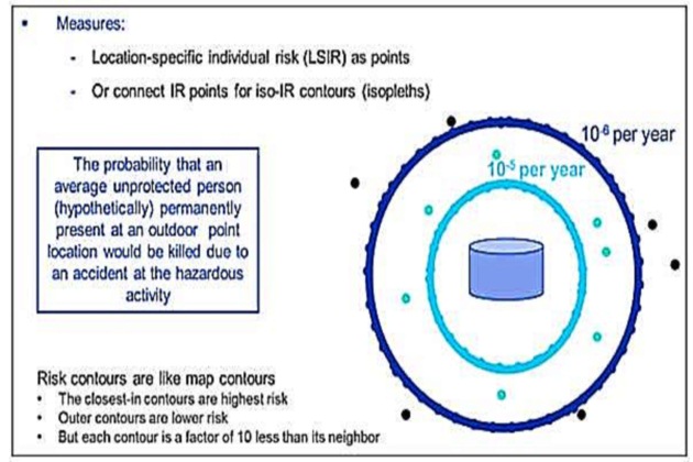
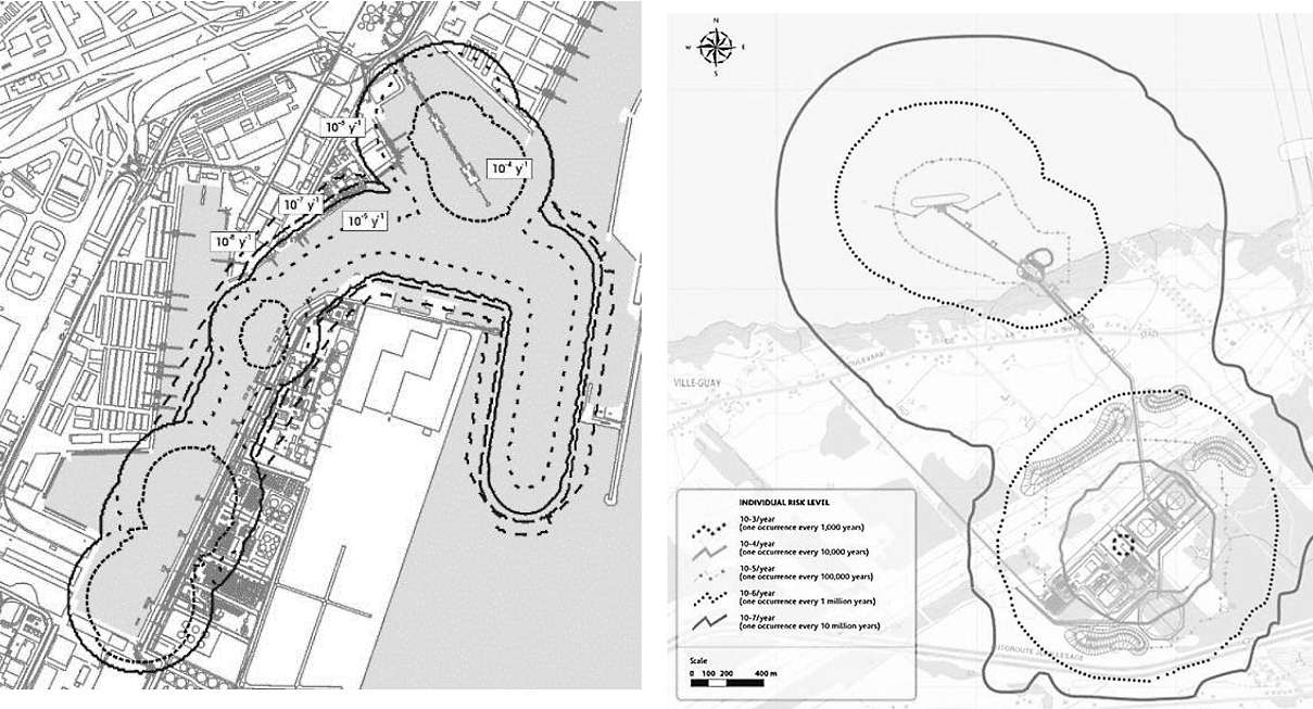
When several specific Safety, Risks and Security Aspects in Liquefied Natural Gas Industryindividual risk contours are composed together they give shape to a combination of ISO curves which are of particular use for land-use planning, as it has been detailed in section “Risk Assessment in Land-Use Planning”.
Figures 13, below, present 2 (two) cases relative to port/terminal areas where individual risk contours combines to produce a land-use map, divided into different risk areas.
Societal risk (SR)
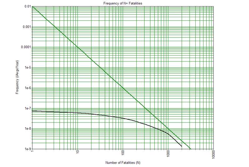
Societal risk is defined as the (cumulative) frequency per year that a particular group of people dies concurrently as a result of accidents. Societal risk criteria have not been as widely used as individual risk criteria because the concepts and calculations involved are much more difficult. Societal risk is represented in an FN curve, which is a Log-log graph: the X-axis represents the number of deaths and the y-axis the cumulative frequency of the accidents, with the number of deaths equal to N or more.
Risk Criteria in ISO/TS 18683
ISO Technical Standard ISO/TS 18683 contains as Annex-A examples of recommended/possible risk criteria of applicable to both QualRA and QRA.
Risk Matrix
ISO 17776:2000, Table A.1, is reproduced in ISO/TS 18683, providing Qualitative Risk Criteria that allows risk ranking, derived from a HAZID report.
The risk analysis shall primarily be carried out with respect to consequences for people, but can require that risk to property and environment is also calculated.
Consequence Category:
A Major injury – long-term disability/health effect.
B Single fatality or multiple major injuries – one death or multiple individuals suffering long-term disability/health effects.
C Multiple fatalities – two or more deaths.
Likelihood Category:
- Remote – 1 in a million or less per year.
- Extremely Unlikely – between 1 in a million and 1 in 100 000 per year.
- Very Unlikely – between 1 in 100 000 and 1 in 10 000 per year.
- Unlikely – between 1 in 10 000 and 1 in 1 000 per year.
- Likely – between 1 in 1 000 and 1 in 100 per year.
The likelihood categories can be related to a ship life or to other time period. For example, assuming a ship lifetime is 25 years, then for a scenario with an annual likelihood of 1 in a million (i. e. rating 1 Remote) the probability of occurrence in the ship’s lifetime is 1 in 40 000 (i. e. 1/(10-6 × 25)).
It will be interesting: Offshore supply chain of Liquefied Natural Gas
If instead of considering a ship lifetime we consider a typical interval consistent with the duration of a bunkering operation we would have, for a TTS operation, 2 hours, i. e. 0.00024 years, the scenario with an annual likelihood of 1 in a million (i. e. rating 1 Remote) the probability of occurrence in the bunkering operation is 1 in 4 166 666 667 (i. e. 1/(10-6 × 0.00024)). This is an extremely low probability which, in good truth, reveals that the adequacy of yearly averaged criteria may represent a limitation when trying to capture the probability of occurrence on a limited duration and infrequent operation. Establishing likelihood criteria “per operation” would probably be more representative avoiding the risk from being averaged over a full year’s length.
Threshold Criteria
Another risk criteria in ISO/TS 18683 indicates a generic Individual Risk limit threshold criteria, as indicated in table 7. This is relevant when it is necessary to assess QRA results, presented with calculated risk figures for selected hazardous scenarios.
| Table 7. Risk Criteria Example – With Individual Risk Thresholds suggested (ISO/TS 18683) | ||
|---|---|---|
| Acceptance criteria | Comment | |
| Individual risk first party personnel | IR < 10-5 | Applies to crew and bunkering personnel directly involved in the activity. |
| Individual risk third-party personnel | IR < 5 · 10-6 | Port personnel and terminal personnel. |
| Individual risk third-party personnel with intermittent risk exposure | Risk contour for IR < 5 · 10-6 | Third-party personnel should not have access for prolonged period. |
| Individual risk third-party personnel with prolonged risk exposure | Risk contour for IR < 10-6 | General public without involvement in the activity. No residential area, schools, hospitals, etc. inside this risk contour. |
Risk criteria in quantitative risk assessments commonly refer to individual risk and societal risk (or group risk), and these are related to fatality or some other measure of harm. Where a significant number of people are exposed to the bunkering operations then both should be assessed. This is also explained in IACS Rec. 142:
…the risk to any individual may be “low” but the risk of harming many people in a single accident/incident might be sufficient to warrant risk reduction. Stakeholders should consider what constitutes a significant number of people to require assessment of societal risk. Dependent upon specifics this might be exposure of ten or more people.
It is important to note that the criteria are typically expressed on a per annum basis (i. e. per year). For hazards that are present for a relatively short time (over a year) the per annum criteria may not be appropriate. This is because the risk is not spread uniformly across the year but peaks intermittently, and for long periods of time it does not exist. As such, if this is not recognised then proposed risk mitigation may not offer the protection envisaged. As a guide, per annum criteria may not be appropriate for a hazard which, like in the case of LNG bunkering, is infrequent and occurs during a very limited part of the year. This had already been recognized in section “Risk Matrix” and PAAs.
Risk-based evaluation of Ports Feasibility for LNG Bunkering
For PAAs willing to evaluate the feasibility of LNG bunkering within the ports under their jurisdiction this Guidance offers, in “Risk-based evaluation of Ports Feasibility for LNG Bunkering”, a collection of tasks that can potentially shape a Technical Specification for a risk-based feasibility study aiming to study the development of LNG bunkering.
Objective
The main objective of the element tasks presented in “Risk-based evaluation of Ports Feasibility for LNG Bunkering” is to provide PAAs with the necessary studies on LNG bunkering infrastructures and/or small storage siting facilities in order to support a safe development of the LNG facilities of the relevant ports or port areas, thus promoting the development LNG bunkering, on a risk-based evaluation.
Tasks
The aim of the task structure suggested in “Risk-based evaluation of Ports Feasibility for LNG Bunkering” is twofold:
- Describe the existing standards/regulations/guidelines related to LNG bunkering and those currently under development. Provide a gap analysis identifying, documenting and comparing the differences between the existing requirements of current/on-going LNG bunkering related regulations. Provide recommendations how to overcome the identified gaps.
- Develop Individual Quantitative Risk Assessments for LNG as fuel bunkering operations, for prospective port(s), taking into consideration specific features of each port such as number and type of ships calling at ports, type of operations, port location and surrounding infrastructures as well as other relevant variables for the establishment of each ports safety/risk profile.
The first point specified above is intended to address the policy and regulatory framework at international, regional and national levels, to define the policy and regulatory context of the relevant port(s).
The second focuses on the study and analysis of specific features of each port in order to assess the risks involved in LNG bunkering on a given port, against specific risk acceptance criteria, taking into consideration geo-morphological and meteorological characteristics affecting the ports, their operational profiles, e. g. types of trade, number of passengers, containers, total number of port calls.
The two points identified above are further subdivided in table 8, below, with specifications into different Tasks ranging from Task 1 to Task 8 as per table below.
| Table 8. Tasks for Risk-based evaluation of LNG bunkering feasibility in Ports | |
|---|---|
| Task | Description |
| 1 | Gap Analysis Study of the Regulatory Frame and Evaluation of Applicable Standards to LNG as fuel for shipping |
| 2 | Feasibility Study |
| 3 | Definition of Risk Acceptance Criteria Study |
| 4 | Site Specific Data Description and Analysis Study |
| 5 | Nautical Analysis and Collision Risk Analysis Study |
| 6 | Hazard Identification – HAZID Study |
| 7 | Quantitative Risk Assessment (QRA) Study |
| 8 | Ship Collision Risk Study |
Each Task, its technical description and expected deliverables, are described in the “Risk-based evaluation of Ports Feasibility for LNG Bunkering”.
The Tasks consist of both generic and port-specific studies, targeting different needs regarding the state of development of the LNG bunkering infrastructures and operations in the relevant port(s). The Tasks are independent amongst them and are non-overlapping. In this way PAA may adopt here a modular construction of possible technical specifications for relevant studies on the feasibility of LNG bunkering development for their ports.
All the Tasks are related to Regulations, Standards, and Risk & Safety, consisting essentially of studies assisting the development and implementation of LNG bunkering facilities within the existing port areas. No engineering implementation studies or works are considered as part of these Tasks.
Good Practice for Ports on Risk Assessment
The elements included in the present section are intended to be taken as good practice recommendations, following from all aspects mentioned in this article. Good Practice approach in Risk Assessment for LNG bunkering projects, in the context of the present Guidance is essentially focused on the procedural aspects, interpretation of Risk Assessment reports and, of remarkable importance, on how to best ensure and evaluate the necessary independency in Risk Assessment activities.
Risk Assessment Methodologies
Different Risk Assessment methodologies are available that may be used to evaluate the safety risks of LNG bunkering projects. The approaches followed, regardless he concrete methodology, should all respect common formal elements which should be enforced by PAAs:
a Adequate description of the basis for the study,
b Description of the systems and definition of operational procedures
c HAZID (identification of team, details of HAZID Workshop, risk ranking exercise with relevant risk matrices, justification for risk screening criteria and identification of the most critical scenarios).
d All hazardous scenarios discussed should be screened in risk matrices, with clear indication of ALARP and most critical scenarios.
e Identification of possible Risk Mitigating measures to address all most critical scenarios.
f Safety Zone calculation.
g Identification of Software used for modelling & analysis (consequence modelling, probability or risk calculation), including validation and identification of analyst.
h Report containing all the minimum elements listed in “Reports” above of the present Guidance.
Risk Acceptance Criteria should be always agreed between operators and PAAs. In the case of existing national legislation and guidance on reference risk criteria thresholds these should be followed. Whenever this is not the case PAAs should agree with acceptable/adequate risk acceptance criteria for the intended risk assessment.
It is possible, and recommended, that PAAs get expert professional advice on the definition of risk acceptance criteria. It should be relevant for the risk assessment being performed.
Read also: Gas Combustion Systems on Liquefied Gas Carriers
Validation of risk acceptance criteria by PAAs should take place well in advance to HAZID workshop or any computational modelling takes place. It is important that all developed tasks within the risk assessment are collectively relevant to the demonstration against the agreed risk criteria.
Whilst defining the minimum requirement of a Qualitative Risk Assessment (QualRA) for all LNG bunkering projects of standard type (PTS, STS and TTS modes), ISO/TS 18683 and IACS Rec.142 are clear in the indication that for those cases diverging from the listed modes, should be subject to a Quantitative Risk Assessment (QRA).
A QRA should be required when:
a Bunkering is not of a standard type (PTS, TTS or STS, in simple standard configuration, as defined in ISO/TS 18683).
b Design, arrangements and operations differ from the guidance given in ISO/TS 18683 or IACS Rec.142.
c Simultaneous Operations (SIMOPS) are planned to take place along with LNG bunkering.
d Automation elements are introduced to significantly reduce human intervention in operations (linked to system analysis).
e A reduction in a Safety Zone is intended, on the basis of consequence/ probabilistic data for the specific LNG bunkering location.
f Whenever a numerical calculation of Risk is required for verification of any given Risk Criteria.
The decision on whether to develop a QualRA or QRA to assess the particular safety risks of an LNG bunkering project should be not only subject to clear requirement from PAA and/or competent authorities responsible for permitting/licensing, it should also reflect the specific characteristics of the project. If no sufficient available data exists for a certain methodology to be applied, PAAs should promote discussion on the best approach to evaluate the risks for that specific project.
Data availability, relevant risk criteria, experienced team, computational resources, adequate modelling assumptions, amongst other factors, all contribute to the quality of the risk assessment results. Adequate consideration should be given to these factors and their potential impact after choosing one specific risk assessment methodology.
Table 9, on the next page, include a list of possible cases where the minimum QualRA prescribed in ISO/TS 18683 may not be enough for risk evaluation and design of the adequate risk mitigation measures.
| Table 9. Standard LNG bunkering scenarios – specific situations where more than the minimum QualRA requirement should be in place. | |||
|---|---|---|---|
| Truck-to-Ship – TTS | 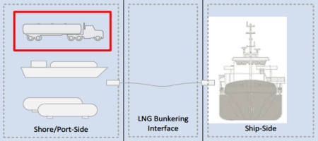 | V ≈ 50 – 100 m3 Q ≈ 40 – 60 m3/h | Multi-LNG truck combination in TTS bunkering mode via common manifold. |
| Higher bunker rate than average (see reference value to the left). | |||
| Use of automated or semi-automated technologies for management of hose handling. | |||
| LNG Fuelling operations in TTS mode, whenever truck unattended (i. e. stand-alone truck supplying LNG during the whole stay of the ship at berth). | |||
| In cases where quantitative risk criteria thresholds are imposed by PAA. | |||
| In all cases where purging and inerting procedures are subject of special considerations, such as a request for exempting inerting on the basis of any special control technology. | |||
| Ship-to-Ship – STS | 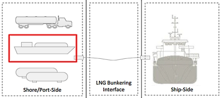 | V ≈ 100 – 6 500 m3 Q ≈ 500 – 1 000 m3/h | Whenever nautical risk assessment identifies particular critical situations (manoeuvring, higher nautical traffic intensity). |
| Higher bunker rate than average (see reference value to the left). | |||
| Cases of bunker barges with no self-propulsion, using tugs for manoeuvring and propulsion. | |||
| In cases where quantitative risk criteria thresholds are imposed by PAA. | |||
| In all cases where purging and inerting procedures are subject of special considerations, such as a request for exempting inerting on the basis of any special control technology. | |||
| Whenever BOG management and vapour return are not in place. | |||
| Terminal (Port)-to-Ship – PTS | 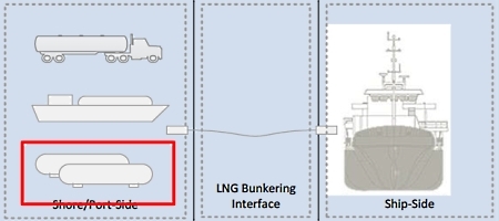 | V ≈ 500 – 20 000 m3 Q ≈ 1 000 – 2 000 m3/h | QRA recommended for all PTS situations, in order to address properly LNG storage elements and distribution pipeline routing within the port area. |
| Higher bunker rate than average (see reference value to the left). | |||
| In cases where quantitative risk criteria thresholds are imposed by PAA. | |||
| In all cases where purging and inerting procedures are subject of special considerations, such as a request for exempting inerting on the basis of any special control technology. | |||
| Whenever BOG management and vapour return are not in place. | |||
Risk Assessment Review
Risk Assessment studies can result in complex reports. PAAs should have in place approval processes well mapped and structured for approval of Risk Assessments which are delivered to satisfy PAA/competent authorities’ requirements for LNG bunkering permitting, location, licensing and operation.
Approval processes should be adequate to the different types of Risk Assessment methodologies.
PAAs should promote staff training on Risk Assessment methodologies, allowing not only for a more active participation of PAA experts in HAZID or HAZOP workshops, where the PAA is part interested, but also to ensure that the appropriate skills and judgement is in place for adequate Risk Assessment review and approval.
Approval criteria and special recommendations from PAAs on risk assessment requirements (in particular those derived from Table 9) should be made available to Operators well in advance to the beginning of risk assessment procedures/tasks.
Quantitative Risk Assessments are model representations of real life physical/ engineering processes. PAAs are recommended to adopt a critical approach in the evaluation of QRAs processes and reports. Many assumptions and QRA-specific aspects are of critical importance to the conclusions derived from the assessment. PAAs should enquire operators and risk analyst on the main aspects behind the risk assessment study. Figure 17, below, includes a collection of some relevant points/clarifications that PAAs are recommended to request close to operators or analysts submitting risk assessment reports.
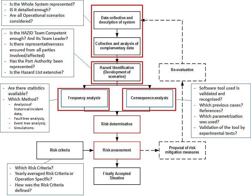
Independency in Risk Assessment
Risk Assessment studies are typically provided by Operators, with possible involvement from consultants or experts in that particular field, produced with the objectives to:
a Satisfy regulatory requirements and relevant risk criteria.
b Support design decisions.
c Develop and implement safe LNG bunkering operations.
The involvement of Ports in those studies has been also an important element, not only through active participation in HAZID meetings but also in the definition of possible hazardous scenarios, input local knowledge, provision of relevant data, amongst other relevant elements.
All those involved in risk studies and risk assessment are interested in the best reassurance of Safety, identification of critical hazardous scenarios and in their adequate cost-effective mitigation.
It will be interesting: The Liquefied Gas Tanker types
It is also important to note, however, that all parts involved, in addition to the best interest of Safety, have also economical interest in the development of LNG bunkering operations, as a relevant port service.
With the above in consideration, it is recommended that PAAs develop and implement the necessary mechanisms and requirements to support transparency and avoid possible conflicts of interest in the development of risk assessments.
Independency and Transparency in Risk Assessment studies should be ensured throughout the whole process. Some recommendations that may be of support to this objective are:
a Requiring Risk Assessment studies to be developed by independent professional in the field of LNG Risk & Safety, with recognized and demonstrated experience.
b Using Risk Criteria which has either been taken from existing legislative framework at national level or, alternatively, which has been imported from an existing published guidance, other country national risk criteria, industry guidance or standard (such as criteria in table 7, taken from ISO/TS 18683).
c To ensure that all assumptions and limitations are well addressed in the risk assessment report.
Good Practice for Risk Assessment Process Flow
The diagram in Figure 18 describes a good practice process flow for Risk Assessment in the particular case of LNG bunkering. It is not intended to represent a requirement nor does it reflect any specific process actually adopted. Its intention is to support PAAs and other involved stakeholders.
The process diagram is, in fact a gross simplification of the many processes that take part in the context of a Risk Assessment, from its scoping and basis definition, down to actual risk calculations and corresponding evaluation.
The diagram is intended to be relevant to both QualRA and QRA approached and it covers the different stages for the Risk Assessment development:
a Scope;
b Preparation;
c HAZID;
d Analysis.
e Assessment.
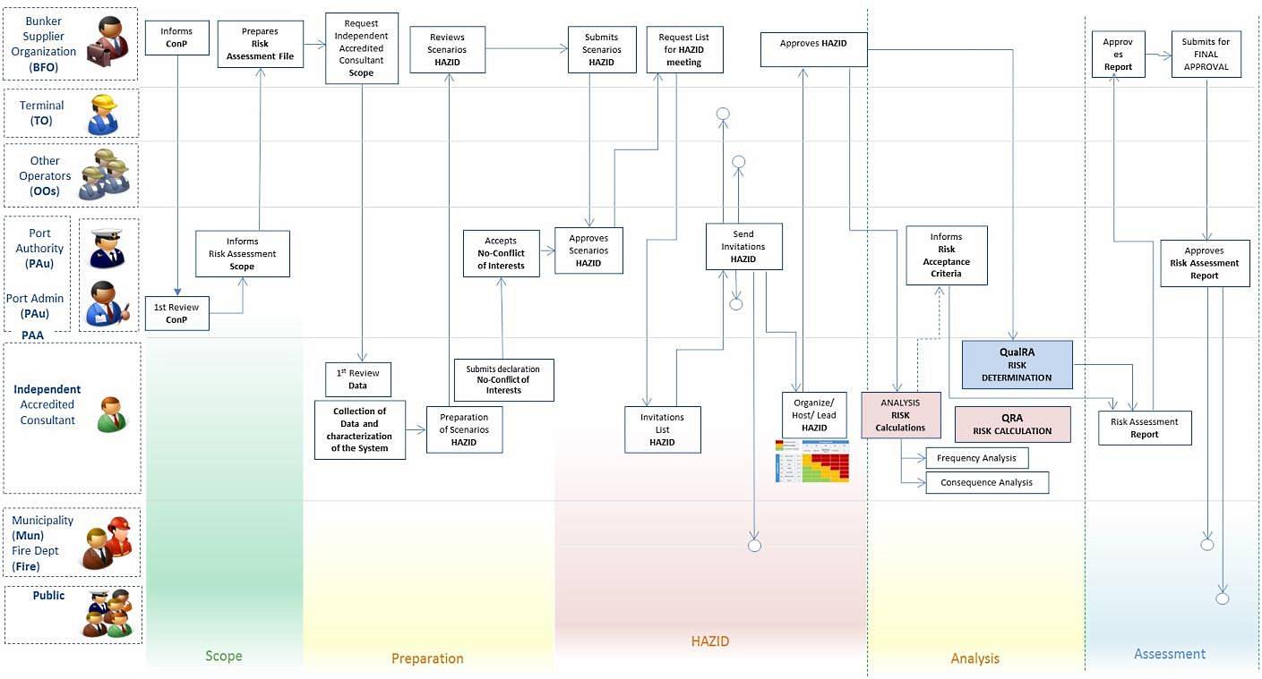

- Study on the completion of an EU framework on LNG-fuelled ships and its relevant fuel provision infrastructure, LOT 1 Position paper: Towards harmonized EU LNG bunkering guidelines, DNV-GL, 2016.
- Study on the completion of an EU framework on LNG-fuelled ships and its relevant fuel provision infrastructure, LOT 1 Final Report, DNV-GL, 2016.
- LNG Bunkering Guidelines IACS Recommendation n. 142, on LNG Bunkering, IACS, 2016.
- ISO/TS 18683:2015. (15-Jan. 2015). Guidelines for systems and installations for supply of LNG as fuel to ships. Technical Specification.
- Society for Gas as a Marine Fuel (SGMF). (2015). Gas as a marine fuel, safety guidelines, Bunkering. Version 1.0, February 2015.
- ISO 20519:2017. Ships and marine technology – Specification for bunkering of gas fuelled ships. (International Standard).
- IEC 60079-10-1. (2015). Explosive atmospheres – Part 10-1: Classification of areas – Explosive gas atmospheres.
- Directive 1999/92/EC – ATEX of the European Parliament and of the Council of 16 December 1999 on minimum requirements for improving the safety and health protection of workers potentially at risk from explosive atmospheres (15th individual Directive within the meaning of Article 16(1) of Directive 89/391/EEC).
- API RP-500. 1997. Recommended practice for classification of locations for electrical installations at petroleum facilities classified as CIass 1, Division 1 and Division 2. Washington. D.C: API.
- API RP-505. 1997, Recommended practice for classification of locations at petroleum facilities classified as Class I, Zone 0, Zone 1 and Zone 2. Washington, D.C. API.
- NFPA 497. 2012, Recommended practice for the classification of flammable liquids, gases or vapours and of hazardous (classified) locations for electrical installations in chemical process areas. Quincy, MA: NFPA.
- IEC EN 60079-10-1 Ed.1.0, 2008. Electrical apparatus for explosive gas atmospheres – Part 10-1: Classification of areas – Explosive gas atmospheres. International Electrotechnical Commission.
- Commission Decision 2010/769/EU of 13 December 2010 on the establishment of criteria for the use by liquefied natural gas carriers of technological methods as an alternative to using low sulphur marine fuels meeting the requirements of Article 4b of Council Directive 1999/32/EC relating to a reduction in the sulphur content of certain liquid fuels as amended by Directive 2005/33/EC of the European Parliament and of the Council on the sulphur content of marine fuels (OJ L 328, 14.12.2010, p. 15).
- USCG CG-OES Policy Letter 02-14 – Guidance Related To Vessels And Waterfront Facilities Conducting Liquefied Natural Gas (LNG) Marine Fuel Transfer (Bunkering) Operations.
- ADN – European Agreement concerning the International Carriage of Dangerous Goods by Inland waterways (Update version ADN January 2017).
- ADR – European agreement concerning the International Carriage of Dangerous Goods by Road (Update version ADR January 2017).
- Rhine Vessel Inspection Regulations (RVIR).
- EU general risk assessment methodology (Action 5 of Multi-Annual Action Plan for the surveillance of products in the EU (COM(2013)76) – Document 2015-IMP-MSG-15 – 16 October 2015.
- Safety Study, Chain analysis: Supplying Flemish ports with LNG as a marine fuel, Analysis of safety aspects, June 2012.
- EN 1160 – Installations And Equipment For Liquefied Natural Gas – General Characteristics Of Liquefied Natural Gas, NBN, 1st edition, August 1996.
- ESD Arrangements & Linked Ship/Shore Systems for Liquefied Gas Carriers, SIGTTO First Edition 2009 – SIGTTO.
- M. Kofod & S. Hartman, T. Mundt – Review of Recent Well-to-Wake Greenhouse Gas Studies evaluating the use of LNG as a marine Fuel, IMO MEPC/INF.15.
- LNG Access Code for Truck Loading for The Zeebrugge LNG Terminal – Based on version approved by the CREG on September 19th 2013 – Applicable as of January 1st 2014 – FLUXYS.
- Guidance for the Prevention of Rollover in LNG Ships – SIGTTO – First Edition 2012.
- Wang, Siyuan & Notteboom, Theo – The role of port authorities in the development of LNG bunkering facilities in North European ports, 14 January 2015, World Maritime University 2015.
- Verhoeven P (2010) A review of port authority functions: towards a renaissance? Marit Policy Manag 37:247-270.
- Society for Gas as a Marine Fuel (SGMF). (2017). Gas as a marine fuel, safety guidelines, Bunkering. Version 2.0, February 2015.
- COM(2003) 515 final – Communication from The Commission concerning the non-binding guide of good practice for implementing Directive 1999/92/EC of the European Parliament and of the Council on minimum requirements for improving the safety and health protection of workers potentially at risk from explosive atmospheres, Brussels, 25.8.2003.
- Davies, P. (2016) – Bunkering LNG: Setting the Safety Zone, 7th Motorship Gas Fuelled Ships Conference, November 2016.
- International Association of Oil & Gas Producers. (1-Mar 2010). Risk Assessment Data Directory – Process Release Frequencies. Report No. 434 – 1, 1 March 2010). Pertinent data from this report is summarised in: Davies & Fort, (Sept 2012), LNG as Marine Fuel – Likelihood of LNG Releases, Journal of Marine Engineering and Technology.
- PGS2 – TNO Yellow Book – Methods for the calculation of physical effects, due to releases of hazardous materials (liquids and gases) – CPR 14E (3rd Edition, 2005) – TNO – The Netherlands Organization of Applied Scientific Research.
- OECD Guiding Principles for Chemical Accident Prevention, Preparedness and Response, Guidance for Industry (including Management and Labour), Public Authorities, Communities, and other Stakeholders – 2nd Edition (2003) – OECD Environment, Health and Safety Publications.
- DNVGL-RP-G105 Edition October 2015 – Development and operation of liquefied natural gas bunkering facilities, Recommended Practice, DNV GL, 2015.
- USCG CG-OES Policy Letter No. 01-17 – Guidance for Evaluating Simultaneous Operations (SIMOPS) during Liquefied Natural Gas (LNG) Fuel Transfer Operations.
- LGC NCOE Field Notice 01-2017 – 14-Aug-17 – Recommended Process For Analysing Risk Of Simultaneous Operations (SIMOPS) During Liquefied Natural Gas (LNG) Bunkering.
- An Overview of Leading Software Tools for QRA, American Society of Safety Engineers – Middle East Chapter (161), 7th Professional Development Conference & Exhibition, March 18-22, 2005.
- Walter Chukwunonso Ikealumba and Hongwei Wu (2016) Some Recent Advances in Liquefied Natural Gas (LNG) Production, Spill, Dispersion, and Safety School of Chemical and Petroleum Engineering, Curtin University.