The present article is dedicated to the operational aspects of LNG bunkering operation, based on the organizational considerations and good practice suggested in article Process Map & Organization of the LNG Bunkering“Proccess Map & Organization”.
- LNG Bunkering Methods
- Truck-to-Ship (TTS)
- Ship-to-Ship (STS)
- Port-to-Ship (PTS)
- Bunkering Procedure
- Step 1 – Initial Precooling 1
- Step 2 – Initial Precooling 2
- Step 3 – Connection of Bunker Hose
- Step 4 – Inerting the Connected System
- Step 5 – Purging the Connected System
- Step 6 – Filling Sequence
- Step 7 – Liquid Line Stripping
- Step 8 – Inerting
- LNG Bunkering Process
- LNG Vapour Management
All references to operational aspects, nomenclature and procedures are consistent with those in IACS Rec. 142 (2015) and SGMF Guidelines v2 (2017).
The standard LNG bunkering procedure can be considered to be well established today, with a significant number of LNG fuel bunkering operations to LNG fuelled ships. Industry guidance (as IACS and SGMF) outlines today the good practice procedures in bunkering operations, streamlining the processes and identifying the major relevant steps in the operation. The different LNG bunkering modes have, to some extent, all been put in practice and experience has been gained by operators. Having the above in consideration, the present article contained herein, do not present colliding provisions or any technical aspects which are not consistent with industry guidance. It is the purpose of this article to provide information to PAAs on the different LNG bunkering modes, generic LNG bunkering process and, more importantly, to suggest good practice procedures for PAAs in the control of LNG bunkering, highlighting the main critical aspects that should be regarded closely from a port authority perspective.
Authorization of LNG bunkering operations will be a responsibility of PAAs. How this “Authorization” takes place, as a result of which process, using which defined communication channels and, finally, based on which documented procedure will this “Authorization” be based upon. Surely Certification of equipment, Training of personnel, amongst other aspects, will be relevant, but it is important to define the exact points where the role of PAAs may be more than a purely passive one, with control checks and support, e. g. in the implementation and enforcement of Control Zones.
Section “LNG Bunkering Methods” presents different LNG bunkering modes and arrangements, further detailing the LNG bunkering modes which have already been outlined in article Comprehensive Overview of LNG: Scope, Characteristics, and Bunkering Solutions“LNG Bunkering Modes”, in particular focusing the TTS, PTS and STS bunkering modes. Section “Bunkering Procedure” is included with an informative set of diagrams for a generic LNG bunkering/fuel transfer operation. Section “LNG Bunkering Process” outlines in detail the generic LNG bunkering process, from pre-bunkering to the final steps upon completion of the operation, underlining the aspects most relevant to PAAs in their supervisory and control functions in LNG bunkering. Section “LNG Vapour Management”, following from article Balancing Cleaner Fuel and Environmental Impact in LNG Emissions“Environment”, highlight the main element for sustainability of LNG bunkering operations: BOG management. From a business and environmental perspective, management of LNG boil-off is an important element to consider throughout the whole bunkering operation. Minimization of BOG should be one of the main optimization criteria for LNG bunkering.
LNG Bunkering Methods
Having already introduced the different LNG bunkering modes, in section Comprehensive Overview of LNG: Scope, Characteristics, and Bunkering Solutions“LNG Bunkering Modes”, these are now presented in more detail, including important aspects which affect the operational performance of the different LNG bunkering methods. In addition, for each bunkering method, single line diagrams are presented to illustrate generic arrangements. Type-C and atmospheric tanks are considered, with the main differences highlighted and illustrated in the different bunkering methods.
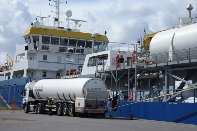
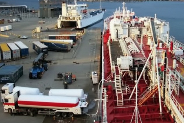
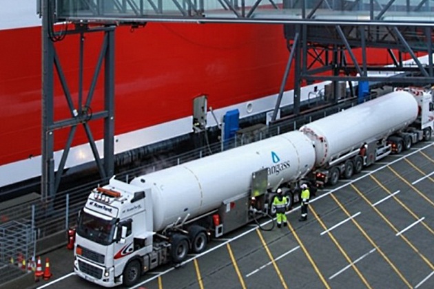
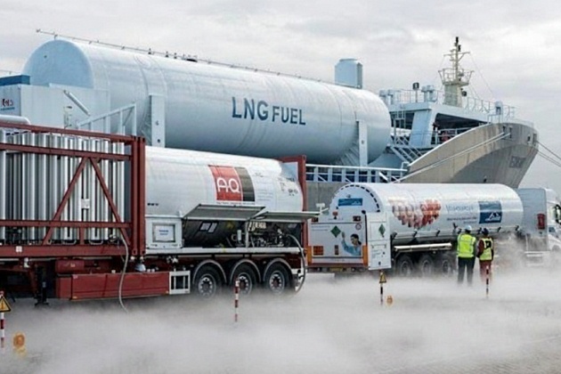
Truck-to-Ship (TTS)
Truck-to-Ship (TTS) LNG bunkering has been a largely adopted method for the initial LNG bunkering implementation. With ships having a small to moderate demand for LNG, of a few hundred cubic meters, TTS has provided for a flexible option, responding to a limited demand. Experience has been gained in procedures and operation with added value to the safe adoption of LNG as fuel.
Read also: LNG (Liquefied Natural Gas) as Fuel
LNG bunkering TTS operations are carried out from typically standardised LNG trucks (of around 40 to 80 m3). With an increasing need for LNG, especially by ships with increased LNG fuel capacity, more than one truck may be required to bunker a single ship, depending on the required bunker volume. This may be achieved either in a sequential manner or, alternatively, through a common bunkering manifold.
On either option the challenges of TTS become noticeable, with increased complexity of operations and largely increased operation time lengths.
As presented in table Comprehensive Overview of LNG: Scope, Characteristics, and Bunkering Solutions“Typical LNG bunkering per different generic ship type”, TTS method may be applied to bunkering volume up to 200-400 m3, depending on the maximum required turn-around times.
Table 1, below, summarizes the main operational aspects of TTS, including also the most relevant limitations.
| Table 1. TTS LNG bunkering mode – Summary table | ||
|---|---|---|
| Truck-to-Ship – TTS | ||
| Short Description | LNG truck connected to the receiving ship on the quayside, using a flexible hose, assisted typically by a hose-handling manual cantilever crane. | |
| Typical Volumes (V) | V ≈ 50-100 m3 | |
| Typical Bunker transfer rates (V) | Q ≈ 40-60 m3/h | |
| Operational characteristics and possibilities | Operational Flexibility, with bunkering possible in different locations within the same port, serving different ships in different conditions. | |
| Operation highly dependent on the transfer capacity of the truck, typically small (see above). | ||
| Possible to deliver LNG very close to receiving ship, minimizing: | heat transfer through the bunkering hose | |
| pressure drop along the bunkering line | ||
| trapped volume, | ||
| Limited Infrastructure requirements, with no necessary | ||
| Possibility to adjust delivered volumes (Nr. of trucks) to different client needs. | ||
| Possibility to adapt to different safety requirements. | ||
| Possibility to serve different LNG fuel users on point-to-point delivery | ||
| RO-RO/PAX ferries may be bunkered from a location in main car/cargo deck. Control for such operation to be | ||
| Limited capacity of trucks: approximately 40-80 m3 is likely to dictate multi-truck operation. | ||
| Limited flow-rates (900-1 200 l/hr) | ||
| Significant impact on other operations involving passengers and/or cargo. | ||
| Limited movement on the quay-side, mostly influenced by the presence of the bunker truck(s). | ||
| Exposure to roadside eventual limitations (permitting, physical limitations, traffic related, etc.) | ||
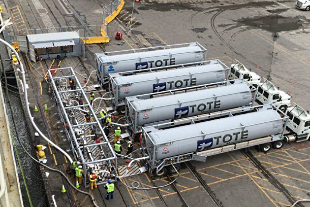
Figures 8 and 9, on the next page, give single-line representations of LNG bunkering generic setup for TTS operation.


Ship-to-Ship (STS)
Table 2, below, summarizes the main operational aspects of STS, including also the most relevant limitations.
| Table 2. STS LNG bunkering mode – Summary table | |
|---|---|
| Ship-to-Ship – STS | |
| Short Description | LNG is delivered to the receiving vessels by another ship, boat or barge, moored alongside on the opposite side to the quay. LNG delivery hose is handled by the bunker. |
| Typical Volumes | V ≈ 100-6 500 m3 |
| Typical Bunker transfer rates (V) | Q ≈ 500-1 000 m3/h |
| Operational characteristics | Generally does not interfere with cargo/passenger handling operations. Simultaneous Operations (SIMOPS) concept is favoured. |
| Most favourable option for LNG bunkering, especially for ships with a short port turnaround time. | |
| Larger delivery capacity and higher rates than TTS method. | |
| Operational flexibility – bunkering can take place alongside, with receiving vessel moored, at anchor or at station. | |
| Limitations | Initial investment costs involving design, procurement, construction and operation of an LNG fuelled vessel/barge. |
| Significant impact in life-cycle cost figures for the specific LNG bunker business. | |
| Limited size for bunker vessel, conditioned by port limitations. | |
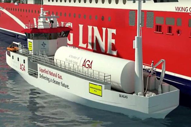
STS bunkering has been a growing operational option for increasing LNG bunkering demands, both in capacity and flow rates. As LNG fuelled ships grow in LNG capacity the need for increased LNG bunkering capacity is also expected to increase.
It will be interesting: Balancing Cleaner Fuel and Environmental Impact in LNG Emissions
STS LNG bunkering represent a particular challenge for PAAs, accounting for the need to consider adequate nautical risk studies that can evaluate and assess the risks in the best possible way. This will not only allow choosing for the best LNG bunkering location but will also contribute to determine the best Practical Aspects of Loran Navigationnavigation route for the bunker vessel, whilst in restricted waters.
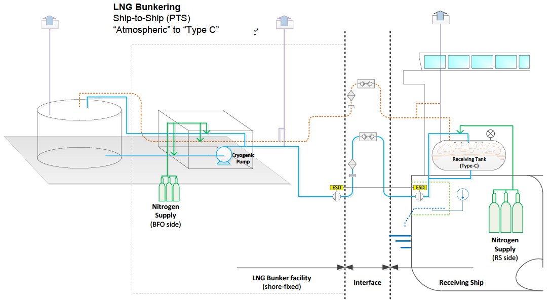
Figures 12 to 14, on the next page, give single-line representations of LNG bunkering generic setup for STS operation.


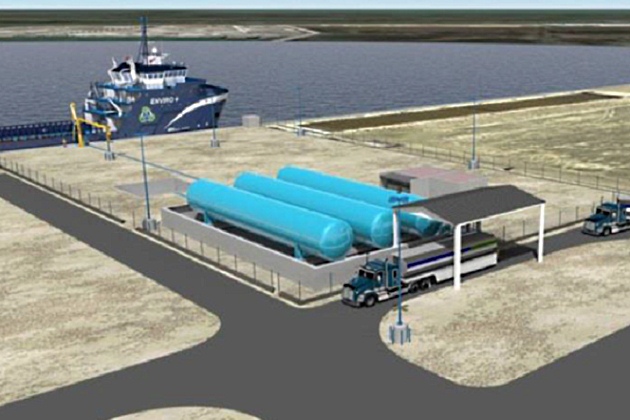
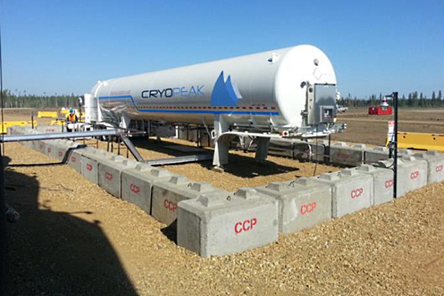
Port-to-Ship (PTS)
Table 3, below, summarizes the main operational aspects of STS, including also the most relevant limitations.
| Table 3. STS LNG bunkering mode – Summary table | |
|---|---|
| Port-to-Ship – PTS | |
| Short Description | LNG is either bunkered directly from a small storage unit (LNG tank) of LNG fuel, small station, or from an import or export terminal. |
| Typical Volumes | V ≈ 500-2 000 m3 |
| Typical Bunker transfer rates (V) | Q ≈ 1 000-2 000 m3/h |
| Operational characteristics | Possibility to deliver larger LNG volumes, at higher rates. |
| Good option for ports with stable, long-term bunkering demand | |
| Limitations | From operational perspective it may be difficult to get the LNG fuelled receiving vessel to the Terminal. |
| Proximity of larger LNG terminal may not be easy to guarantee. | |
| Calculation of available LNG for delivery, in small storage tanks, can be difficult unless pre-established contract exist | |
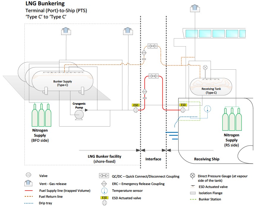
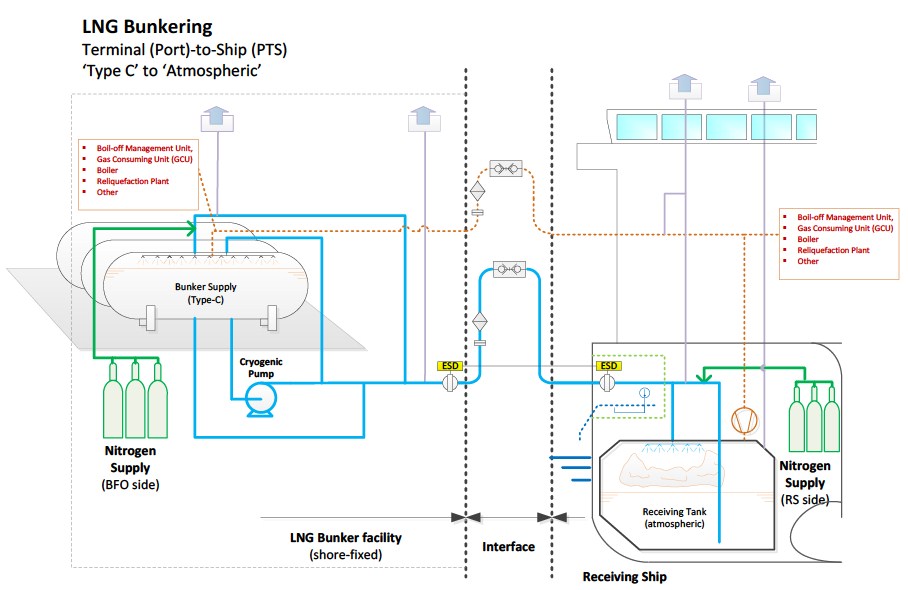
Figures 15 and 17, on the next page, give single-line representations of LNG bunkering generic setup for TTS operation.
Bunkering Procedure
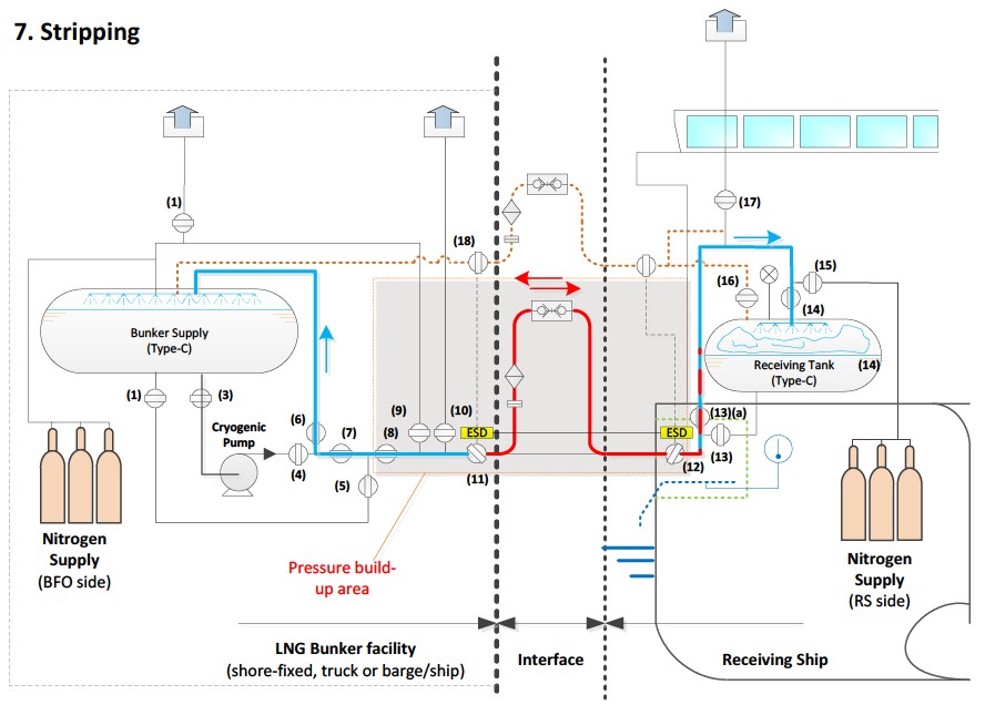
Even though not directly involved in the direct LNG bunkering operation, PAAs should have a clear structured perception of which different steps take part during LNG transfer. For that purpose, and having a generic LNG bunkering single-line “type-C to type-C” arrangement, as represented in figure 18, below, the generic LNG bunkering operation is presented in this section to best support PAA in the understanding of the generic different stages involved.
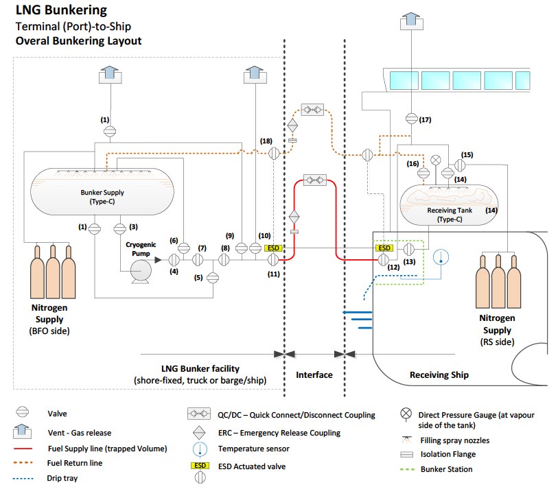
Initially all valves are closed as shown in the diagram. The transfer hose is not connected until step three but included in this diagram. The first step takes place during ship mooring or in the case of LNG Ship-to-Ship Transfer Processship-to-ship transfer during the bunker vessels mooring up against the receiving ship. Discharging unit can be either: terminal, truck or bunker vessel/barge. Variations in design and layout can take place, but overall this is a representative example of a layout and it gives a good basis for explaining the bunkering procedure.
Read also: The Role of LNG Bunkering Infrastructure
To be noted, in particular, that different arrangements are possible that will in practice be implemented, with different technological solutions, connectors, hose length, GCUs, storage, control mechanisms, manifolds, etc. The main objective of the present section is to differentiate between the different operational stages during LNG bunkering:
- Initial Cooling;
- Connection;
- Inerting;
- Purging;
- Filling sequence;
- Stripping;
- Inerting (final inerting of bunkering lines).
It is possible that, under specific project arrangements and risk assessment, some of the phases generically represented in this section, may either not take place, or be done differently, bases on the specific technological details in place.
Figure 18 represents the complete system on a generic Port-to-Ship arrangement.
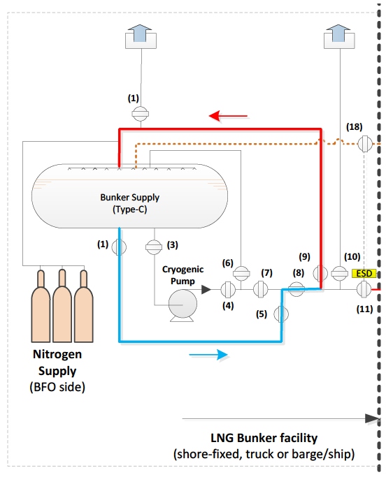
Step 1 – Initial Precooling 1
Filling lines are precooled in advance to operation. Valves V2, V5, V8 and V9 are opened. The system needs to be cooled down slowly, otherwise one part will contract and another not. Improper cooling could also lead to pipe cracking. The precooling sequence depends on Use of Cargo Pumps on Liquefied Gas Carrierscargo pump, design of the discharging unit and size of installation. Cold LNG (blue) exits tank 1 form the bottom, and slowly “pushes” the warmer NG (red) in the pipes into the top of tank 1.
During this stage both units must check temperature and pressure of their respective LNG tanks. Within the tank, temperature is directly correlated with pressure. If the temperature of the receiving tank is significantly higher than the discharging, there will be an initial excessive vaporization when starting to transfer LNG. This will likely increase the tank pressure and potentially trigger the pressure relief valve to open if the pressure exceeds the set limit. For his reason, the pressure of both tanks must be reduced prior to the bunkering in case of a high receiving tank temperature. In addition, it is also here important to note, when the levels in the receiving tank are low, the rate of evaporation and heat ingress to the tank increases, causing a higher‐pressure build-up.
The transfer of LNG requires a certain pressure difference, which generally is determined by the pump/PBU and the pressure in the receiving tank. The larger the pressure difference, the more efficient the transfer. For TTS bunkering with flow rates of around 50 m3/h, a typical transfer pump can deliver at around 4 barg. In a warm tank, the pressure may be as high as 5 barg. To be able to conduct the transfer you need a lower pressure in the receiving tank than what is delivered by the pump.
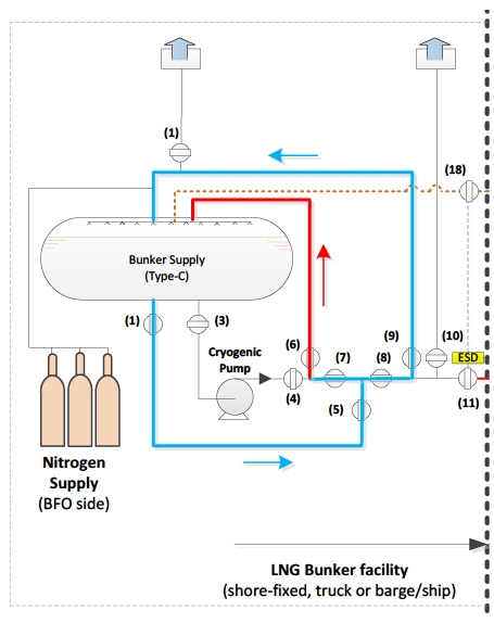
Step 2 – Initial Precooling 2
The fixed speed cargo pump at the discharging unit also requires precooling. Valves in step 1 remain opened and additionally valves V3, V4 and V6 are opened. For transfers where the pressure difference between the discharging and receiving unit is greater than 2 barg, tank 1 pressure will be utilized as a driving force. This makes the cargo pump redundant.
Step 3 – Connection of Bunker Hose
All previously opened valves are now closed. Dedicated discharging units may be fitted with specialized hose handling equipment (i. e. hose crane) or loading arms, to deliver the bunker hose to the receiving ship. The hose is connected to the manifold. Each manifold are to be earthed and the receiving ship shall be equipped with an insulating flange near the coupling to prevent a possible ignition source due to electrostatic build‐up. One or two flexible hoses will be connected between the units – one liquid filling hose and one vapour return hose if needed. For smaller transfers with capacities range of around 50‐200 m3/h, and where the receiving tank is a type C tank with the possibility of sequential filling, a vapour‐return hose will generally not be needed. For larger transfer rates a vapour return line may be used in order to decrease the time of the bunkering.
Step 4 – Inerting the Connected System
Inert gas, nitrogen (green), is used to remove moisture and oxygen (below 4 %) from tank 2 and associated piping. Inerting is accomplished by sequential pressurization and depressurization of the system with nitrogen. Presence of moisture in the tanks or pipes will create hydrates, which is a form of ice lumps that will be difficult to remove from the system. Oxygen in the system would here produce an explosive atmosphere inside the LNG transfer line leading to a hazardous situation that needs to be avoided through inerting. Valves opened: V10, V11, V12 and V16.

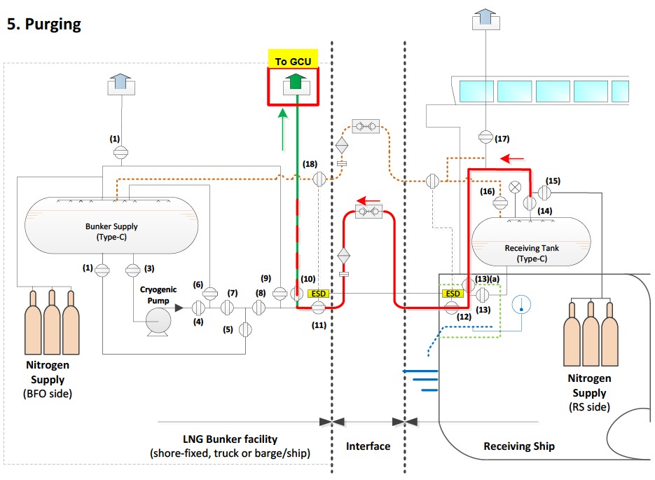
Step 5 – Purging the Connected System
The remaining system is purged with NG (until it reaches 97‐98 % ratio), to remove remaining nitrogen according to engine specifications. Valve V16 is closed prior to purging. Valve V15 is opened, natural gas is now moving out from the receiving tank. Venting trace amount of methane through the mast should be subject to due consideration. Venting should not be allowed, and any possible necessary release of excessive LNG boil-off/gas should be done through a GCU/Oxidizer/Flare or equivalent system. Valve V10 should be closed quickly after the pipes have been cleaned so as not to let too much methane escape through the vent.
Step 6 – Filling Sequence
For the filling sequence both bottom filling and top filling (the shower/spray) can be used. For top filling valve V15 remains open, for bottom filling it is closed and valve V13 is opened. To start the transfer from tank 1 to tank 2 valves V3, V4, V7, V8, V11 and V12 also have to be opened. Common practice is to start with top filling as this will reduce the pressure in the fuel tank, and then move over to bottom filling when a satisfying pressure is achieved. A high pressure in the receiving tank will make it harder for the LNG transfer to take place and the pump would have to work with higher pressure and higher energy consumption.

Transfer speed range from 100‐1 000 m3/h depending on scenario, tanks and equipment, and whether bottom or top filling is used. Bottom filling can take much higher volumes than top filling. Bottom filling is therefore preferred with respect to time, but it is important that the tank pressure allows for this to take place. Sequential filling i. e. alterations between top and bottom filling during the transfer is also standard practice, to control the pressure in the receiving tank.

This rate can be withheld during the transfer until agreed amount is reached. The transfer is to be monitored on both ships with regards to system pressure, tank volume and equipment behaviour. This procedure is to be performed for each tank regardless of fuel type. Maximum level for filling the LNG tanks is 98 % of total volume according to class rules, but is normally lower for system design reasons.
Step 7 – Liquid Line Stripping
The liquid that remains in the bunker hoses, after the pump has stopped, must be drained before disconnection. Valves V3, V4 and V11 on discharging unit are closed, while valve V6 is opened. This valve links to the top of the fuel tank. This process creates a pressure build‐up due to a rise in temperature in the remaining liquid left in the pipes and hose. LNG residuals in these areas are forced into both tanks. Subsequent opening and closing of the shipside valve V12, pushes the remaining LNG into the receiving ships tanks.
Step 8 – Inerting
In a process in everything similar to Step 4 the LNG bunkering line should be inerted in the end of operation, prior to disconnection.
LNG Bunkering Process
The diagram in figure 26, below, outlines the different stages of a generic LNG bunkering operation, from Pre-Bunkering to Post-Bunkering, including the different elements that should be expected in the adequate operational description of a time-sequence for LNG bunkering.
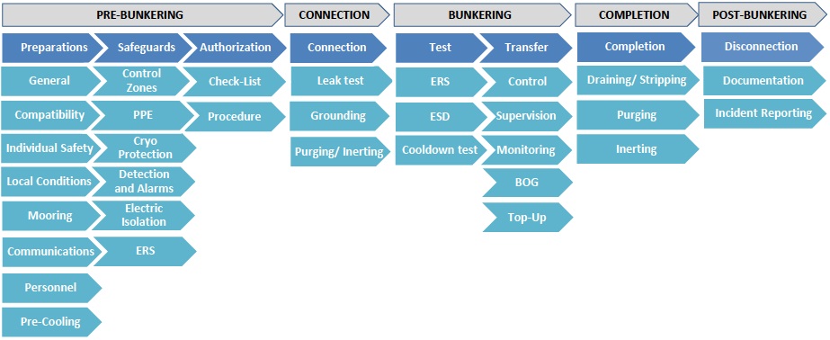
In the diagram above, in figure 26, it is possible to see all the elementary steps that compose a typical LNG bunkering operation. Detailing each of the operational elements above is not within the scope of the EMSA Guidance, with existing references today already providing, collectively, an excellent operational description of how the different aspects should be covered.
It will be interesting: Maritime Standards Explained. A Focus on EN ISO 20519, ISO/TS 18683, and Supporting Guidelines
The industry has very recently built up significant experience and know-how and any transcription in this Guidance would lead to potential good operational practice, updated in thee reference documents listed below, failing to be updated in this article. To avoid this from happening no transcriptions or adaptation of operational related text has been attempted in this section, only providing for the relevant references.
The following references should be taken into account for the full description of the LNG bunkering operational process:
| Document | By | Short description/Section for Transfer Procedures |
| EN ISO 20519 – Specification for bunkering of liquefied natural gas fuelled vessels | ISO | Section 6.5 – Transfer Procedures LNG Bunker Check-Lists in Annex |
 | Fully consistent with the IGF Code (6.5.1) | |
| Minimum staffing during bunkering (responsibility to the vessel captain/facility) – (6.5.2) | ||
| Always 2 PICs (one on either side of the bunkering line/operation) engaged in nothing else – (6.5.2.1) | ||
| Manifold Watch (on receiving vessel) – (6.5.2.2) | ||
| Hose watch (on bunker vessel/facility) – (6.5.2.3) | ||
| Check-list procedure (6.5.3) – Pre-Operation | ||
| LNG bunker supplier responsibility to inform RSO on local requirements (6.5.4) | ||
| PIC conference (6.5.5) – Decision on leading PIC | ||
| Bunker transfer equipment responsibility (6.5.6) | ||
| Communications (6.5.7) | ||
| Check-list procedure (6.5.8) – Pre-Bunkering | ||
| Purging/drainage of hose lines (6.5.9) | ||
| PPE (6.5.10) | ||
| LNG BDN (6.5.11) | ||
| Post Transfer Conference and check-list (6.5.12) |
ISO 20519, as described before, should be taken as the main reference for the operational requirements that should be observed and verified in place by PAAs.
Other references will however, read in conjunction with ISO 20519, provide a much in-depth detail of operational procedures, covering all relevant elements, as represented in figure 24. These are identified below (IACS Rec.142, and SGMF Bunkering Guidelines):
| Document | By | Short description/Section for Transfer Procedures | ||
 | IACS Rec 142 LNG Bunkering Guidelines | IACS | For IACS | |
| Section 1 Pre-bunkering phase | 1.1 Definition | |||
| 1.2 Goal | ||||
| 1.3 Functional requirements | ||||
| 1.4 General requirements | ||||
| 1.5 Preparation for bunker transfer | ||||
| 1.6 Pre-bunkering checklist | ||||
| 1.7 Connection of the transfer system | ||||
 | SGMF | SGMF | Section 2 Bunkering phase | 2.1 Definition |
| LNG Bunkering Guidelines | 2.2 Goal | |||
| Safety Guidelines | 2.3 Functional requirements | |||
| Version 2 April 2017 | 2.4 General requirements | |||
| Section 3 Bunkering completion phase | 3.1 Definition | |||
| 3.2 Goal | ||||
| 3.3 Functional requirements | ||||
| 3.4 Draining, purging and inerting sequence | ||||
| 3.5 Post-bunkering documentation | ||||
LNG Vapour Management
Boil-Off Gas (BOG), a subject already addressed in article Balancing Cleaner Fuel and Environmental Impact in LNG EmissionsК“Environment”, id here re-visited from an operational perspective, since BOG is very likely the most relevant parameter shaping LNG bunkering operations.
BOG is a relevant issue associated to LNG storage but not only. Also the differences in temperature between LNG supply and receiving tanks will dictate the LNG transfer mode, pressure and overall operation management. This has already been demonstrated before, in section “Bunkering Procedure”, with the filling sequence highly dependent on temperature and pressure on both sides of the bunkering lines.
Typical boil-off rates are 0,1-0,5 % per day in storage due to heat ingress (even in tanks with very good vacuum insulation. Additional BOG is formed when the LNG is transferred into tanks with higher pressures, half or partially-filled or even when part LNG is left in transfer/bunkering lines for too long. It is important to manage BOG that is generated therefore in:
- Storage (in any of the LNG bunkering sides);
- Transfer/bunkering lines;
- Distribution lines.
By removing boil-off gas (recondensing/liquefying/consuming), pressure and temperature are kept at controlled constant levels. If boil-off gas is not removed, pressure builds-up and – if not managed – would eventually lead to the opening of pressure relief systems, in what is called as “venting” (an event which can only be considered as an emergency.
But managing BOG is, in fact, more complex than it already seems: When boil-off gas is removed to maintain the pressure level, the methane number decreases because the LNG gets heavier. This is important for LNG as fuel customers because most engines require a minimum methane number to prevent knocking. It is important for the receiving ship to adequately maintain proper storage temperatures and pressures, compensating for some BOG with the showering of cold LNG by top-filling line.
If not removed, boil-off gas can be contained under pressure. Pressure will be decreased by emptying the tank and/or refilling it with sub cooled LNG recondensing BOG. BOG is an important aspect in the LNG supply chain that must be taken into account during the complete life-cycle of LNG bunkering operations.
The BOG management required at various supply chain stages depends mainly on the pressure build-up that can be allowed in the supply chain from liquefaction to end-customer. Large LNG customers are mostly energy consumers/producers (like regas to power plants) using atmospheric storage (pressure slightly above 1 bar). Often the LNG is taken-off from these facilities in a gaseous form. Hence the large scale LNG supply requires significant BOG management all over the chain.
Read also: LNG Bunkering Guide – What It Is and How to Use It
The BOG management system (removal) will help to keep LNG colder. LNG cold stored under atmospheric pressure can be delivered to any type of receiving ship LNG tank. On the other hand LNG stored under pressure (therefore warm) can only be delivered to a receiving ship LNG tank that has the same type of pressure storage unless BOG has been removed before. There are significant operational implications in having the right arrangement, and temperatures agreed to ensure adequate LNG transfer arrangement.
In the case of LNG fuelled ships using pressurized storage (type-C tanks), pressure-build up (by a PBU) can be a positive design aspect, as there would be no need for an LNG compressor to deal with the excessive BOG. On these terminals, BOG (pressure build-up) can be handled solely by sufficient throughput, sub cooled LNG and vapour collapse (top spray).
Table 4, below, identifies some of the relevant BOG mitigation measure, in the way to avoid excessive LNG vapour generation.
| Table 4. BOG mitigating measures | |||
|---|---|---|---|
| BOG mitigations | Mode | Advantage | Disadvantage |
| Top spray | LNG transfer | Effective, vapor collapse. Low cost solution | Requires internals and topfill line + ESD valves. Only if pressurized tank |
| Vapor return | LNG transfer | Relative low cost solution | Contributes to solution, but rarely a standalone solution (depending on flowrate) |
| BOG compressor | LNG transfer & storage | Allows BOG to be used as fuel gas/regen gas or re-liquefy. Enables to keep pressure constant. Can be single BOG managment mitigation method | Very costly Maintenance, reliability. If subject to high flow changes, need an bypass to flare/vent |
| Minimaze heat ingress | LNG transfer & storage | Effective. Many options available (superinsulated/vacuum/PUR/EPS/PIR). Can be double containment (safety) | Contributes to solution, but rarely a standalone solution (depending on flowrate) |
| High throughput | LNG storage | Very effective. No CAPEX | Contribute to solution, but rarely a standalone solution (depending on flowrate). Most effective with sub-cooled LNG. Limited by customer demand and optimal parcel size |
| Pressurized storage | LNG storage | Allows more BOG accumulation. Could eliminate the need for pumps | Max volume constraints. End-customer constraints |
| In tank Reliquefying (coil) | LNG storage | Allows BOG intake. Enables to keep pressure constant | Requires another cryogenic tank. Coolant refilling required |

- Study on the completion of an EU framework on LNG-fuelled ships and its relevant fuel provision infrastructure, LOT 1 Position paper: Towards harmonized EU LNG bunkering guidelines, DNV-GL, 2016.
- Study on the completion of an EU framework on LNG-fuelled ships and its relevant fuel provision infrastructure, LOT 1 Final Report, DNV-GL, 2016.
- LNG Bunkering Guidelines IACS Recommendation n. 142, on LNG Bunkering, IACS, 2016.
- ISO/TS 18683:2015. (15-Jan. 2015). Guidelines for systems and installations for supply of LNG as fuel to ships. Technical Specification.
- Society for Gas as a Marine Fuel (SGMF). (2015). Gas as a marine fuel, safety guidelines, Bunkering. Version 1.0, February 2015.
- ISO 20519:2017. Ships and marine technology – Specification for bunkering of gas fuelled ships. (International Standard).
- IEC 60079-10-1. (2015). Explosive atmospheres – Part 10-1: Classification of areas – Explosive gas atmospheres.
- Directive 1999/92/EC – ATEX of the European Parliament and of the Council of 16 December 1999 on minimum requirements for improving the safety and health protection of workers potentially at risk from explosive atmospheres (15th individual Directive within the meaning of Article 16(1) of Directive 89/391/EEC).
- API RP-500. 1997. Recommended practice for classification of locations for electrical installations at petroleum facilities classified as CIass 1, Division 1 and Division 2. Washington. D.C: API.
- API RP-505. 1997, Recommended practice for classification of locations at petroleum facilities classified as Class I, Zone 0, Zone 1 and Zone 2. Washington, D.C. API.
- NFPA 497. 2012, Recommended practice for the classification of flammable liquids, gases or vapours and of hazardous (classified) locations for electrical installations in chemical process areas. Quincy, MA: NFPA.
- IEC EN 60079-10-1 Ed.1.0, 2008. Electrical apparatus for explosive gas atmospheres – Part 10-1: Classification of areas – Explosive gas atmospheres. International Electrotechnical Commission.
- Commission Decision 2010/769/EU of 13 December 2010 on the establishment of criteria for the use by liquefied natural gas carriers of technological methods as an alternative to using low sulphur marine fuels meeting the requirements of Article 4b of Council Directive 1999/32/EC relating to a reduction in the sulphur content of certain liquid fuels as amended by Directive 2005/33/EC of the European Parliament and of the Council on the sulphur content of marine fuels (OJ L 328, 14.12.2010, p. 15).
- USCG CG-OES Policy Letter 02-14 – Guidance Related To Vessels And Waterfront Facilities Conducting Liquefied Natural Gas (LNG) Marine Fuel Transfer (Bunkering) Operations.
- ADN – European Agreement concerning the International Carriage of Dangerous Goods by Inland waterways (Update version ADN January 2017).
- ADR – European agreement concerning the International Carriage of Dangerous Goods by Road (Update version ADR January 2017).
- Rhine Vessel Inspection Regulations (RVIR).
- EU general risk assessment methodology (Action 5 of Multi-Annual Action Plan for the surveillance of products in the EU (COM(2013)76) – Document 2015-IMP-MSG-15 – 16 October 2015.
- Safety Study, Chain analysis: Supplying Flemish ports with LNG as a marine fuel, Analysis of safety aspects, June 2012.
- EN 1160 – Installations And Equipment For Liquefied Natural Gas – General Characteristics Of Liquefied Natural Gas, NBN, 1st edition, August 1996.
- ESD Arrangements & Linked Ship/Shore Systems for Liquefied Gas Carriers, SIGTTO First Edition 2009 – SIGTTO.
- M. Kofod & S. Hartman, T. Mundt – Review of Recent Well-to-Wake Greenhouse Gas Studies evaluating the use of LNG as a marine Fuel, IMO MEPC/INF.15.
- LNG Access Code for Truck Loading for The Zeebrugge LNG Terminal – Based on version approved by the CREG on September 19th 2013 – Applicable as of January 1st 2014 – FLUXYS.
- Guidance for the Prevention of Rollover in LNG Ships – SIGTTO – First Edition 2012.
- Wang, Siyuan & Notteboom, Theo – The role of port authorities in the development of LNG bunkering facilities in North European ports, 14 January 2015, World Maritime University 2015.
- Verhoeven P (2010) A review of port authority functions: towards a renaissance? Marit Policy Manag 37:247-270.
- Society for Gas as a Marine Fuel (SGMF). (2017). Gas as a marine fuel, safety guidelines, Bunkering. Version 2.0, February 2015.
- COM(2003) 515 final – Communication from The Commission concerning the non-binding guide of good practice for implementing Directive 1999/92/EC of the European Parliament and of the Council on minimum requirements for improving the safety and health protection of workers potentially at risk from explosive atmospheres, Brussels, 25.8.2003.
- Davies, P. (2016) – Bunkering LNG: Setting the Safety Zone, 7th Motorship Gas Fuelled Ships Conference, November 2016.
- International Association of Oil & Gas Producers. (1-Mar 2010). Risk Assessment Data Directory – Process Release Frequencies. Report No. 434 – 1, 1 March 2010). Pertinent data from this report is summarised in: Davies & Fort, (Sept 2012), LNG as Marine Fuel – Likelihood of LNG Releases, Journal of Marine Engineering and Technology.
- PGS2 – TNO Yellow Book – Methods for the calculation of physical effects, due to releases of hazardous materials (liquids and gases) – CPR 14E (3rd Edition, 2005) – TNO – The Netherlands Organization of Applied Scientific Research.
- OECD Guiding Principles for Chemical Accident Prevention, Preparedness and Response, Guidance for Industry (including Management and Labour), Public Authorities, Communities, and other Stakeholders – 2nd Edition (2003) – OECD Environment, Health and Safety Publications.
- DNVGL-RP-G105 Edition October 2015 – Development and operation of liquefied natural gas bunkering facilities, Recommended Practice, DNV GL, 2015.
- USCG CG-OES Policy Letter No. 01-17 – Guidance for Evaluating Simultaneous Operations (SIMOPS) during Liquefied Natural Gas (LNG) Fuel Transfer Operations.
- LGC NCOE Field Notice 01-2017 – 14-Aug-17 – Recommended Process For Analysing Risk Of Simultaneous Operations (SIMOPS) During Liquefied Natural Gas (LNG) Bunkering.
- An Overview of Leading Software Tools for QRA, American Society of Safety Engineers – Middle East Chapter (161), 7th Professional Development Conference & Exhibition, March 18-22, 2005.
- Walter Chukwunonso Ikealumba and Hongwei Wu (2016) Some Recent Advances in Liquefied Natural Gas (LNG) Production, Spill, Dispersion, and Safety School of Chemical and Petroleum Engineering, Curtin University.
I DON'T INDERSTAND ENGLISH, AND I WOULD LIKE FRENCH TRANSLATION