Natural Gas Processing is the essential sequence of operations required to condition raw natural gas for long-distance transport and consumer use. The core objective is the separation of valuable products and removal of contaminants, including liquid hydrocarbons, water, and acidic compounds like hydrogen sulfide and carbon dioxide.
The specific configuration of Process Modules – such as phase separation, acid gas treating, dehydration, and liquid recovery – is customized during the design stage. This optimization depends fundamentally on the gas stream’s composition, the required sales specifications, and the logistics of the gas field’s location.
Introduction
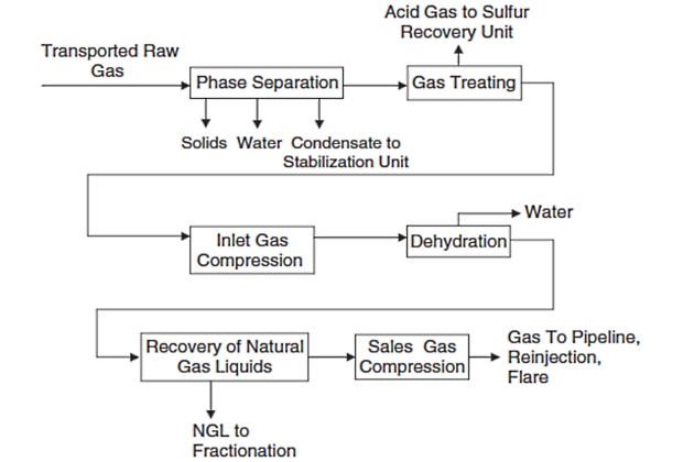
Raw natural gas after transmission through the field-gathering network must be processed before it can be moved into long-distance pipeline systems for use by consumers. The objective of gas processing is to separate natural gas, condensate, noncondensable, acid gases, and water from a gas-producing well and condition these fluids for sale or disposal. The typical process operation modules are shown in Figure below. Each module consists of a single piece or a group of equipment performing a specific function. All the modules shown will not necessarily be present in every gas plant. In some cases, little processing is needed; however, most natural gas requires processing equipment at the gas processing plant to remove impurities, water, and excess hydrocarbon liquid and to control delivery pressure. The unit operations used in a given application may not be arranged in the sequence shown in Figure below, although this sequence is typical. The choice of modules to be used and the arrangement of these modules are determined during the design stage of each gas-field development project.
Unfortunately, at the individual module level the design may be sound and the operation correct but could result in a poor gas processing facility.
The reason is that each module has varying characteristics under varying loads, which can result in a type of internal incompatibility. For instance, a given unit module may require a particular inlet composition to produce the desired output. If a previous unit does not maintain this, the downstream unit may not operate satisfactorily. Thus, the fault might not lie so much with that unit but with total plant design, even though the unit module is usually blamed.
The individual unit modules of Figure above are briefly reviewed here with greater details to follow in subsequent chapters.
Process Modules
The first unit module is the physical separation of the distinct phases, which are:
- typically gas,
- liquid hydrocarbons,
- liquid water,
- and/or solids.
Separation of the Gas Produced in Field from Unnecessary ComponentsPhase separation of the production stream is usually performed in an inlet separator. Inlet gas receiving is complicated by the fact that transmission lines supplying the plant typically operate with two or three phases present and consequently liquid slugging is common. Slugs are normally formed from elevational changes in the inlet supply pipes, changes in Demand, Supply, and Market Outlook of Liquefied Gas Global Tradegas supply flow rates, and changes in pressure and temperature during transmission. Slug flow may even be encountered in horizontal pipes under steady-state conditions if the flow regime is not properly selected. The arrival of “slugs” at production or processing equipment impacts the operation of production facilities negatively, causing both mechanical problems (due to high velocities and momentum) and process problems (increasing liquid levels, causing surges and trips). In some cases operators can minimize liquid accumulation by managing fields and pipelines in such a way as to create a suitable fluid flow regime (i. e., mist flow regime) in which the gas velocity is high enough to keep liquids dispersed continuously. While it is desirable to design the flow lines to avoid slugging, in practice this can be difficult while maintaining the ability to turn down the pipeline flow rate. In these cases, consideration should be given to providing suitable process equipment to diminish the effect of slugging. Gas pipelines have typically used slug catchers to dissipate the energy of the liquid slugs, to minimize turbulence, to ensure that the gas and liquid flow rates are low enough so that the stratified flow regime and subsequently gravity segregation can occur. The slug catcher is designed to separate gas, hydrocarbon condensate, and inlet water. The gas stream is sent to the inlet separators.
Read also: Maritime Decarbonization Ecology Innovation and the Path to Zero Emissions
The separators usually contain vane elements to aid in the coalescence of liquids. They may also include filters to remove particulates and may be followed by suction scrubbers if compressors are needed to bring low-pressure gas up to high pressure for further processing operations. The liquids that collect in the slug catcher flow to a three-phase separator from which the two liquid phases, hydrocarbon condensate and water/methanol or water/glycol phases, are outputs. Overhead gas from the three-phase separator is recompressed where necessary for use as fuel gas. More detailed information about phase separation is presented in article “Phase Separation: An Essential Process in Hydrocarbon ProductionPhase Separation“.
Hydrocarbon condensate recovered from Mastering Natural Gas Fundamentals Properties Sources and Transport Insightsnatural gas may be shipped without further processing but is typically stabilized to produce a safetransportable liquid. Unstabilized condensates contain a large percentage of methane and ethane, which will vaporize easily in LNG IMO Tanks/Containment Systemsstorage tanks.
Stabilization is the full removal of light fractions from the condensate, usually achieved by distillation. Stabilized liquid will generally have a vapor pressure specification (Reid vapor pressure Vapour pressure at 100 °F. Reid vapor pressure is a standard indicator of volatility and a key quality control factor, particularly when considering condensate storage.x of <10 psi), as the product will be injected into a pipeline or transport pressure vessel, which has definite pressure limitations. Condensate stabilization is discussed in article “Industrial Practices for Condensate Stabilization and Storage ManagementCondensate Stabilization“.
The next step in natural gas processing is acid gas treating. In addition to heavy hydrocarbons and water vapor, natural gas often contains other contaminants that may have to be removed. Carbon dioxide (CO2), hydrogen sulfide (H2S), and other sulfur-containing species such as mercaptans are compounds that require complete or partial removal. These compounds are collectively known as “acid gases“. H2S when combined with water forms a weak sulfuric acid, whereas CO2 and water form carbonic acid, thus the term “acid gas“. Natural gas with H2S or other sulfur compounds present is called “sour gas“, whereas gas with only CO2 is called “sweet“. Both H2S and CO2 are very undesirable, as they cause corrosion and present a major safety risk. Treating processes for receiving these components are covered in article “Navigating Acid Gas Treating and Sulfur ReclamationAcid Gas Treating“.
Depending on the pressure at the plant gate, the next step in processing will either be inlet compression to an “interstage” pressure, typically 300-400 psig (compression is discussed in article “Reciprocating and Centrifugal Compressor Comparison for Natural Gas CompressionNatural Gas Compression“), or be dew point control and natural gas liquid recovery. Water dew point control is required to meet specifications and to control hydrate formation. Gas hydrate formation is a major concern for engineers in pipeline and Natural Gas Transportation in the Form of Hydrate Pellets (NGHP)natural gas transportation industries as it causes choking/plugging of pipelines and other related problems. Methods of preventing hydrate formation in the plant include lowering the hydrate formation temperature with chemical inhibition or dehydration to remove the water. Gas dehydration is discussed in detail in article “Process and Operational Challenges in Natural Gas Dehydration SystemsNatural Gas Dehydration“.
Hydrocarbon dew point or hydrocarbon liquid recovery involves cooling the gas and condensing out the liquids. Hydrocarbon dew point control can be either dehydration followed by cooling/condensation or by a combination of inhibition/cooling/condensation processes. Refrigeration is performed either by autorefrigeration due to a pressure drop across a valve or by an external mechanical refrigeration process. The temperature to which the gas is cooled depends on whether it is necessary to meet a sales gas hydrocarbon dew point specification or whether substantial liquid recovery is desired. Three situations motivate maximum condensate recovery. The first is the desire to maximize condensate production when processing associated gas. The second situation occurs when processing retrograde condensate gas; here the objective is to recover the condensate and reinject the gas into the formation. Third, in some markets the natural gas liquids (NGLs) produced from the condensate may be more valuable as liquid products than as sales gas components, i. e., their recovery will yield a better profit. Whether to leave maximum NGLs in the gas stream (but still attaining sales hydrocarbon dew point specification) or to recover them as liquids is purely an economic decision made by comparing their value as heat versus the equivalent value as liquid chemical feedstock. If the equivalent liquid value is lower than the gas, NGLs should be left in the gas to the extent as possible. However, if the equivalent liquid value is higher than the LNG and Domestic Gas Value Chainsgas value, then liquid recovery should be maximized. Natural gas processing for liquid recovery is discussed in article “Natural Gas Processing and Liquids RecoveryNatural Gas Liquids Recovery“.
If gas is produced at lower pressures than typical sales Piping System of pressure vessels on gas tankerspipeline pressure (approximately 700-1 000 psig), it is compressed to sales gas pressure.
Transport of sales gas is done at high pressure in order to reduce pipeline diameter. Pipelines may operate at very high pressures (above 1 000 psig) to keep the gas in the dense phase thus preventing condensation and two-phase flow. Compression typically requires two to three stages to attain sales gas pressure. As stated previously, processing may be done after the first or second stage, prior to sales compression. More details are available in article “Principles and Design of Sales Gas Transmission SystemsSales Gas Transmission“.
Where there is no available gas pipeline, separated associated gas may be flared. The ability to flare depends on regulations as well as the field location. Increasingly in such cases, separated gas is being conserved by compression and reinjection into producing formations for eventual recovery and sales. Also, in gas condensate reservoirs, the gas is often reinjected, or “cycled“, to enable higher net recovery of valuable liquid hydrocarbons from the reservoir.
Scope of Natural Gas Processing
The important factors that usually determine the extent of gas processing include the processing objectives, the type or source of the gas, and the location and size of the gas fields.
Processing Objectives
If the natural gas is transportated by pipeline, the processing installation must be designed to meet either transport or final specifications. Processing of a gas stream may have one of the following three basic objectives.
- To produce a sales gas stream that meets specifications of the type shown in Table below. These specifications are mainly intended to meet pipeline requirements and the needs of industrial and domestic consumers.
- To maximize NGLs production by producing a lean gas stripped of most of the hydrocarbons other than methane.
- To deliver a commercial gas. Such gas must be distinguished by a certain range of gross heating value lying.
Effect of Gas Type in Field Processing
The gas composition of the field is the most important issue in choosing a processing scheme. In other words, depending on the type of reservoir and the composition of the produced gas, the Gas Handling Equipment for Efficient Gas Processinggas processing plant may contain extensive facilities for the processing of the associated liquefiable hydrocarbons.
| Natural Gas Specifications in the Salable Gas Stream | |
|---|---|
| Characteristic | Specification |
| Water content | 4-7 lb/MMscf (max) |
| Hydrogen sulfide content | 1/4 grain/100 scf (max) |
| Gross heating value | 950 Btu/scf (min) |
| Hydrocarbon dew point | 15 °F at 800 psig (max) |
| Mercaptan content | 0,2 grain/100 scf (max) |
| Total sulfur content | 1–5 grain/100 scf (max) |
| Carbon dioxide content | 1-3 mole percent (max) |
| Oxygen content | 0-0,4 mole percent (max) |
| Sand, dust, gums, and free liquid | Commercially free. |
| Typical delivery temperature | 120 °F |
| Typical delivery pressure | 714,7 psia |
Typically, associated gas is very rich in liquefiable hydro-carbons and must undergo NGL and condensate recovery to meet hydrocarbon dew point or minimum heating value requirements. The gas processing scheme will also be dictated by the format of the sales contract and its specifications. The contract may be totally different for each customer depending on the composition and amount of gas, plant recoveries, and the contractual preferences of the customer.
Location of the Gas Field
The productivity of a gas reservoir can vary greatly and depend primarily on type, location, and age. Because the location and output of the wells can vary widely, then not surprisingly, the systems that have been designed to collect and process this output also vary widely.
It will be interesting: Introduction to the Standard Simulation Tests and Requirements for Naval Hydrodynamics
There are at least two aspects of location that are important: remoteness and local temperature variation. Temperature affects the tendency for hydrate formation in the gas gathering network. Offshore platforms and “outbacks” are examples of remote locations. Even these locales are not strictly comparable because one is sea based vs dry land based. For the sea-based facility the produced fluid from each wellhead flows via a flow line into a manifold and from there to the process facilities located on the platform deck. Ship platforms are extremely limited with respect to size and allowable weight and only those operations absolutely needed are performed. Facilities on the Offshore terminal for transshipment of liquefied gasoffshore platform will generally process the gas to produce a low water content hydrocarbon stream for export to shore through the subsea pipelines. This process ensures minimal corrosion, as well as minimizing the potential for hydrate formation in the raw gas pipeline. A dry-land outback facility has essentially unlimited area available and can support operations not practical or desirable offshore, such as treating or processing involving fire hazards.

- Acikgoz, M., Franca, F., and Lahey Jr, R. T., An experimental study of three-phase flow regimes. Int. J. Multiphase Flow 18(3), 327-336 (1992).
- Adewmi, M. A., and Bukacek, R. F., Two-phase pressure drop in horizontal pipelines. J. Pipelines 5, 1-14 (1985).
- Amdal, J., et al., “Handbook of Multiphase Metering”. Produced for The Norwegian Society for Oil and Gas Measurement, Norway (2001).
- Ansari, A. M., Sylvester, A. D., Sarica, C., Shoham, O., and Brill, J. P., A comprehensive mechanistic model for upward two-phase flow in wellbores. SPE Prod. Facilit. J. 143-152 (May 1994).
- API, “Computational Pipeline Monitoring”. API Publication 1130, 17, American Petroleum Institute, TX (1995a).
- API, “Evaluation Methodology for Software Based Leak Detection Systems”. API Publication 1155, 93, American Petroleum Institute, TX (1995b).
- API RP 14E, “Recommended Practice for Design and Installation of Offshore Production Platform Piping Systems”, 5th Ed., p. 23.
- Asante, B., “Two-Phase Flow: Accounting for the Presence of Liquids in Gas Pipeline Simulation”. Paper presented at 34th PSIG Annual Meeting, Portland, Oregon (Oct. 23–25, 2002).
- AsphWax’s Flow Assurance course, “Fluid Characterization for Flow Assurance”. AsphWax Inc., Stafford, TX (2003).
- Ayala, F. L., and Adewumi, M. A., Low-liquid loading multiphase flow in natural gas pipelines. ASME J. of Energy Res. Technol. 125, 284-293 (2003).
- Baillie, C., and Wichert, E., Chart gives hydrate formation temperature for natural gas. Oil Gas J. 85(4), 37-39 (1987).
- Baker, O., Design of pipelines for simultaneous flow of oil and gas. Oil Gas J. 53, 185 (1954).
- Banerjee, S., “Basic Equations”. Lecture presented at the Short Course on Modeling of Two-Phase Flow Systems, ETH Zurich, Switzerland (March 17-21, 1986).
- Barnea, D., A unified model for prediction flow pattern transitions for the whole range of pipe inclinations. Int. J. Multiphase Flow 13(1), 1-12 (1987).
- Barnea, D., and Taitel, Y., Stratified three-phase flow in pipes: Stability and transition. Chem. Eng. Comm. 141–142, 443-460 (1996).
- Battara, V., Gentilini, M., and Giacchetta, G., Condensate-line correlations for calculating holdup, friction compared to field data. Oil Gas J. 30, 148–52 (1985).
- Bay, Y., “Pipelines and Risers”, Vol. 5. Elsevier Ocean Engineering Book Series (2001).
- Beggs, H. D., and Brill, J. P., “A Study of Two-Phase Flow in Inclined Pipes”. JPT, 607-17; Trans., AIME, 255 (May 1973).
- Bendiksen, K., Brandt, I., Jacobsen, K. A., and Pauchon, C., “Dynamic Simulation of Multiphase Transportation Systems”. Multiphase Technology and Consequence for Field Development Forum, Stavanger, Norway (1987).
- Bendiksen, K., Malnes, D., Moe, R., and Nuland, S., The dynamic two-fluid model OLGA: Theory and application. SPE Prod. Eng. 6, 171-180 (1991).
- Bertola, V., and Cafaro, E., “Statistical Characterization of Subregimes in Horizontal Intermittent Gas/Liquid Flow”. Proc. the 4th International Conference on Multiphase Flow, New Orleans, LA (2001).
- Bjune, B., Moe, H., and Dalsmo, M., Upstream control and optimization increases return on investment. World Oil 223, 9 (2002).
- Black, P. S., Daniels, L. C., Hoyle, N. C., and Jepson, W. P., Studying transient multiphase flow using the pipeline analysis code (PLAC). ASME J. Energy Res. Technol. 112, 25-29 (1990).
- Bloys, B., Lacey, C., and Lynch, P., “Laboratory Testing and Field Trial of a New Kinetic Hydrate Inhibitor”. Proc. 27th Annual Offshore Technology Conference, OTC 7772, PP. 691-700, Houston, TX (1995).
- Bonizzi, M., and Issa, R. I., On the simulation of three-phase slug flow in nearly horizontal pipes using the multi-fluid model. Int. J. Multiphase Flow 29, 1719-1747 (2003).
- Boriyantoro, N. H., and Adewumi, M. A., “An Integrated Single-Phase/Two-Phase Flow Hydrodynamic Model for Predicting the Fluid Flow Behavior of Gas Condensate Pipelines”. Paper presented at 26th PSIG Annual Meeting, San Diego, CA (1994).
- Brauner, N., and Maron, M. D., Flow pattern transitions in two-phase liquid-liquid flow in horizontal tubes, Int. J. Multiphase Flow 18, 123-140 (1992).
- Brauner, N., The prediction of dispersed flows boundaries in liquid-liquid and gas-liquid systems, Int. J. Multiphase Flow 27, 885-910 (2001).
- Brill, J. P., and Beggs, H. D., “Two-Phase Flow in Pipes”, 6th Ed. Tulsa University Press, Tulsa, OK (1991).
- Bufton, S. A., Ultra Deepwater will require less conservative flow assurance approaches. Oil Gas J. 101(18), 66-77 (2003).
- Campbell, J. M., “Gas Conditioning and Processing”, 3rd Ed. Campbell Petroleum Series, Norman, OK (1992).
- Carroll, J. J., “Natural Gas Hydrates: A Guide for Engineers”. Gulf Professional Publishing, Amsterdam, The Netherlands (2003).
- Carroll, J. J., “An Examination of the Prediction of Hydrate Formation Conditions in Sour Natural Gas”. Paper presented at the GPA Europe Spring Meeting, Dublin, Ireland (May 19-21, 2004).
- Carson, D. B., and Katz, D. L., Natural gas hydrates. Petroleum Trans. AIME 146, 150-158 (1942).
- Chen, C. J., Woo, H. J., and Robinson, D. B., “The Solubility of Methanol or Glycol in Water-Hydrocarbon Systems”. GPA Research Report RR-117, Gas Processors Association, OK (March 1988).
- Chen, X., and Guo, L., Flow patterns and pressure drop in oil-air-water three-phase flow through helically coiled tubes. Int. J. Multiphase Flow 25, 1053-1072 (1999).
- Cheremisinoff, N. P., “Encyclopedia of Fluid Mechanics”, Vol. 3. Gulf Professional Publishing, Houston, TX (1986).
- Chisholm, D., and Sutherland, L. A., “Prediction of Pressure Gradient in Pipeline Systems during Two-Phase Flow”. Paper presented at Symposium on Fluid Mechanics and Measurements in Two-Phase Flow Systems, Leeds (Sept. 1969).
- Cindric, D. T., Gandhi, S. L., and Williams, R. A., “Designing Piping Systems for Two-Phase Flow”. Chem. Eng. Progress, 51-59 (March 1987).
- Collier, J. G., and Thome, J. R., “Convective Boiling and Condensation”, 3rd Ed. Clarendon Press, Oxford, UK (1996).
- Colson, R., and Moriber, N. J., Corrosion control. Civil Eng. 67(3), 58-59 (1997).
- Copp, D. L., “Gas Transmission and Distribution”. Walter King Ltd., London (1970).
- Courbot, A., “Prevention of Severe Slugging in the Dunbar 16 Multiphase Pipelines”. Paper presented at the Offshore Technology Conference, Houston, TX (May 1996).
- Covington, K. C., Collie, J. T., and Behrens, S. D., “Selection of Hydrate Suppression Methods for Gas Streams”. Paper presented at the 78th GPA Annual Convention, Nashville, TN (1999).
- Cranswick, D., “Brief Overview of Gulf of Mexico OCS Oil and Gas Pipelines: Installation, Potential Impacts, and Mitigation Measures”. U. S. Department of the Interior, Minerals Management Service, Gulf of Mexico OCS Region, New Orleans, LA (2001).
- Dhl, E., et al., “Handbook of Water Fraction Metering”, Rev. 1. Norwegian Society for Oil and Gas Measurements, Norway (June 2001).
- Decarre, S., and Fabre, J., Etude Sur La Prediction De l’Inversion De Phase. Revue De l’Institut Francais Du Petrole 52, 415-424 (1997).
- De Henau, V., and Raithby, G. D., A transient two-fluid model for the simulation of slug flow in pipelines. Int. J. Multiphase Flow 21, 335–349 (1995).
- Dukler, A. E., “Gas-Liquid Flow in Pipelines Research Results”. American Gas Assn. Project NX-28 (1969).
- Dukler, A. E., and Hubbard, M. G., “The Characterization of Flow Regimes for Horizontal Two-Phase Flow”. Proc. Heat Transfer and Fluid Mechanics Institute, 1, 100-121, Stanford University Press, Stanford, CA (1966).
- Eaton, B. A., et al., The prediction of flow pattern, liquid holdup and pressure losses occurring during continuous two-phase flow in horizontal pipelines. J. Petro. Technol. 240, 815-28 (1967).
- Edmonds, B., et al., “A Practical Model for the Effect of Salinity on Gas Hydrate Formation”. European Production Operations Conference and Exhibition, Norway (April 1996).
- Edmonds, B., Moorwood, R. A. S., and Szczepanski, R., “Hydrate Update”. GPA Spring Meeting, Darlington (May 1998).
- Esteban, A., Hernandez, V., and Lunsford, K., “Exploit the Benefits of Methanol”. Paper presented at the 79th GPA Annual Convention, Atlanta, GA (2000).
- Fabre, J., et al., Severe slugging in pipeline/riser systems. SPE Prod. Eng. 5(3), 299-305 (1990).
- Faille, I., and Heintze, E., “Rough Finite Volume Schemes for Modeling Two-Phase Flow in a Pipeline”. In Proceeding of the CEA.EDF.INRIA Course, INRIA Rocquencourt, France (1996).
- Fidel-Dufour, A., and Herri, J. S., “Formation and Dissociation of Hydrate Plugs in a Water in Oil Emulsion”. Paper presented at the 4th International Conference on Gas Hydrates, Yokohama, Japan (2002).
- Frostman, L. M., “Anti-aggolomerant Hydrate Inhibitors for Prevention of Hydrate Plugs in Deepwater Systems”. Paper presented at the SPE Annual Technical Conference and Exhibition, Dallas, TX (Oct. 1-4, 2000).
- Frostman, L. M., et al., “Low Dosage Hydrate Inhibitors (LDHIs): Reducing Total Cost of Operations in Existing Systems and Designing for the Future”. Paper presented at the SPE International Symposium on Oilfield Chemicals, Houston, TX (Feb. 5-7, 2003).
- Frostman, L. M., “Low Dosage Hydrate Inhibitor (LDHI) Experience in Deepwater”. Paper presented at the Deep Offshore Technology Conference, Marseille, France (Nov. 19-21, 2003).
- Fuchs, P., “The Pressure Limit for Terrain Slugging”. Proceeding of the 3rd BHRA International Conference on Multiphase Flow, Hague, The Netherlands (May 1987).
- Furlow, W., “Suppression System Stabilizes Long Pipeline-Riser Liquid Flows”. Offshore, Deepwater D&P, 48 + 166 (Oct., 2000).
- Giot, M., “Three-Phase Flow”, Chap. 7.2. McGraw-Hill, New York (1982).
- Goulter, D., and Bardon, M., Revised equation improves flowing gas temperature prediction. Oil Gas J. 26, 107-108 (1979).
- Govier, G. W., and Aziz, K., “The Flow of Complex Mixtures in Pipes”. Van Nostrand Reinhold Co., Krieger, New York (1972).
- GPSA Engineering Data Book, 11th Ed. Gas Processors Suppliers Association, Tulsa, OK (1998).
- Gregory, G. A., and Aziz, K., Design of pipelines for multiphase gas-condensate flow. J. Can. Petr. Technol. 28-33 (1975).
- Griffith, P., and Wallis, G. B., Two-phase slug flow. J. Heat Transfer Trans. ASME. 82, 307-320 (1961).
- Haandrikman, G., Seelen, R., Henkes, R., and Vreenegoor, R., “Slug Control in Flowline/Riser Systems”. Paper presented at the 2nd International Conference on Latest Advance in Offshore Processing, Aberdeen, UK (Nov. 9-10, 1999).
- Hall, A. R. W., “Flow Patterns in Three-Phase Flows of Oil, Water, and Gas”. Paper presented at the 8th BHRG International Conference on Multiphase Production, Cannes, France (1997).
- Hammerschmidt, E. G., Formation of gas hydrates in natural gas transmission lines. Ind. Eng. Chem. 26, 851-855 (1934).
- Hart, J., and Hamersma P. J. Correlations predicting frictional pressure drop and liquid holdup during horizontal gas-liquid pipe flow with small liquid holdup. Int. J. Multiphase Flow 15(6), 974-964 (1989).
- Hartt, W. H., and Chu, W., New methods for CP design offered. Oil Gas J. 102(36), 64-70 (2004).
- Hasan, A. R., Void fraction in bubbly and slug flow in downward two-phase flow in vertical and inclined wellbores, SPE Prod. Facil. 10(3), 172–176 (1995).
- Hasan, A. R., and Kabir, C. S., “Predicting Multiphase Flow Behavior in a Deviated Well”. Paper presented at the 61st SPE Annual Technical Conference and Exhibition, New Orleans, LA (1986).
- Hasan, A. R., and Kabir, C. S., Gas void fraction in two-phase up-flow in vertical and inclined annuli. Int. J. Multiphase Flow 18(2), 279-293 (1992).
- Hasan, A. R., and Kabir, C. S., Simplified model for oil/water flow in vertical and deviated wellbores. SPE Prod. Facil. 14(1), 56-62 (1999).
- Hasan, A. R., and Kabir, C. S., “Fluid and Heat Transfers in Wellbores”. Society of Petroleum Engineers (SPE) Publications, Richardson, TX (2002).
- Havre, K., and Dalsmo, M., “Active Feedback Control as the Solution to Severe Slugging”. Paper presented at the SPE Annual Technical Conference and Exhibition, New Orleans, LA (Oct. 3, 2001).
- Havre, K., Stornes, K., and Stray, H., “Taming Slug Flow in Pipelines”. ABB Review No. 4, 55-63, ABB Corporate Research AS, Norway (2000).
- Hedne, P., and Linga, H., “Suppression of Terrain Slugging with Automatic and Manual Riser Chocking”. Advances in Gas-Liquid Flows, 453-469 (1990).
- Hein, M., “HP41 Pipeline Hydraulics and Heat Transfer Programs.” PennWell Publishing Company, Tulsa, OK (1984).
- Henriot, V., Courbot, A., Heintze, E., and Moyeux, L., “Simulation of Process to Control Severe Slugging: Application to the Dunbar Pipeline”. Paper presented at the SPE Annual Conference and Exhibition, Houston, TX (1999).
- Hewitt, G. F., and Roberts, D. N., “Studies of Two-Phase Flow Patterns by Simultaneous X-ray and Flash Photography”. AERE-M 2159, HMSO (1969).
- Hill, T. H., Gas injection at riser base solves slugging, flow problems. Oil Gas J. 88(9), 88-92 (1990).
- Hill, T. J., “Gas-Liquid Challenges in Oil and Gas Production”. Proceeding of ASME Fluids Engineering Division Summer Meeting, Vancouver, BC, Canada (June 22-26, 1997).
- Holt, A. J., Azzopardi, B. J., and Biddulph, M. W., “The Effect of Density Ratio on Two-Phase Frictional Pressure Drop”. Paper presented at the 1st International Symposium on Two-Phase Flow Modeling and Experimentation, Rome, Italy (Oct. 9-11, 1995).
- Holt, A. J., Azzopardi, B. J., and Biddulph, M. W., Calculation of two-phase pressure drop for vertical up flow in narrow passages by means of a flow pattern specific models. Trans. IChemE 77(Part A), 7-15 (1999).
- Hunt, A., Fluid properties determine flow line blockage potential. Oil Gas J. 94(29), 62–66 (1996).
- IFE, “Mitigating Internal Corrosion in Carbon Steel Pipelines”. Institute of Energy Technology News, Norway (April 2000).
- Jansen, F. E., Shoham, O., and Taitel, Y., The elimination of severe slug-ging, experiments and modeling. Int. J. Multiphase Flow 22(6), 1055-1072 (1996).
- Johal, K. S., et al., “An Alternative Economic Method to Riser Base Gas Lift for Deepwater Subsea Oil/Gas Field Developments”. Proceeding of the Offshore Europe Conference, 487-492, Aberdeen, Scotland (9-12 Sept., 1997).
- Jolly, W. D., Morrow, T. B., O’Brien, J. F., Spence, H. F., and Svedeman, S. J., “New Methods for Rapid Leak Detection in Offshore Pipelines”. Final Report, SWRI Project No. 04-4558, SWRI (April 1992).
- Jones, O. C., and Zuber, N., The interrelation between void fraction fluctuations and flow patterns in two-phase flow Int. J. Multiphase Flow. 2, 273-306 (1975).
- Kang, C., Wilkens, R. J., and Jepson, W. P., “The Effect of Slug Frequency on Corrosion in High-Pressure, Inclined Pipelines”. Paper presented at the NACE International Annual Conference and Exhibition, Paper No. 96020, Denver, CO (March 1996).
- Katz, D. L., Prediction of conditions for hydrate formation in natural gases. Trans. AIME 160, 140–149 (1945).
- Kelland, M. A., Svartaas, T. M., and Dybvik, L., “New Generation of Gas Hydrate Inhibitors”. 70th SPE Annual Technical Conference and Exhibition, 529-537, Dallas, TX (Oct. 22-25, 1995).
- Kelland, M. A., Svartaas, T. M., Ovsthus, J., and Namba, T., A new class of kinetic inhibitors. Ann. N. Y. Acad. Sci. 912, 281-293 (2000).
- King, M. J. S, “Experimental and Modelling Studies of Transient Slug Flow”. Ph.D. Thesis, Imperial College of Science, Technology, and Medicine, London, UK (March 1998).
- Klemp, S., “Extending the Domain of Application of Multiphase Technology”. Paper presented at the 9th BHRG International Conference on Multiphase Technology, Cannes, France (June 16-18, 1999).
- Kohl, A. L., and Risenfeld, F. C., “Gas Purification.” Gulf Professional Publishing, Houston, TX (1985).
- Kovalev, K., Cruickshank, A., and Purvis, J., “Slug Suppression System in Operation”. Paper presented at the 2003 Offshore Europe Conference, Aberdeen, UK (Sept. 2-5, 2003).
- Kumar, S., “Gas Production Engineering”. Gulf Professional Publishing, Houston, TX (1987).
- Lagiere, M., Miniscloux, and Roux, A., Computer two-phase flow model predicts pipeline pressure and temperature profiles. Oil Gas J. 82-91 (April 9, 1984).
- Langner, et al., “Direct Impedance Heating of Deepwater Flowlines.” Paper presented at the Offshore Technology Conference (OTC), Houston, TX (1999).
- Lederhos, J. P., Longs, J. P., Sum, A., Christiansen, R. l., and Sloan, E. D., Effective kinetic inhibitors for natural gas hydrates. Chem. Eng. Sci. 51(8), 1221-1229 (1996).
- Lee, H. A., Sun, J. Y., and Jepson, W. P., “Study of Flow Regime Transitions of Oil-Water-Gas Mixture in Horizontal Pipelines”. Paper presented at the 3rd International Offshore and Polar Engng Conference, Singapore (June 6–11 1993).
- Leontaritis, K. J., “The Asphaltene and Wax Deposition Envelopes”. The Symposium on Thermodynamics of Heavy Oils and Asphaltenes, Area 16C of Fuels and Petrochemical Division, AIChE Spring National Meeting and Petroleum Exposition, Houston, TX (March 19-23, 1995).
- Leontaritis, K. J., “PARA-Based (Paraffin-Aromatic-Resin-Asphaltene) Reservoir Oil Characterization”. Paper presented at the SPE International Symposium on Oilfield Chemistry, Houston, TX (Feb. 18-21, 1997a).
- Leontaritis, K. J., Asphaltene destabilization by drilling/completion fluids. World Oil 218(11), 101-104 (1997b).
- Leontaritis, K. J., “Wax Deposition Envelope of Gas Condensates”. Paper presented at the Offshore Technology Conference (OTC), Houston, TX (May 4–7 1998).
- Lin, P. Y., and Hanratty, T. J., Detection of slug flow from pressure measurements. Int. J. Multiphase Flow 13, 13-21 (1987).
- Lockhart, R. W., and Martinelli, R. C., Proposed correlation of data for isothermal two-phase, two-component flow in pipes. Chem. Eng. Prog. 45, 39-48 (1949).
- Maddox, R. N., et al., “Predicting Hydrate Temperature at High Inhibitor Concentration”. Proceedings of the Laurance Reid Gas Conditioning Conference, 273-294, Norman, OK (1991).
- Mann, S. L., et al., “Vapour-Solid Equilibrium Ratios for Structure I and II Natural Gas Hydrates”. Proceedings of the 68th GPA Annual Convention, 60-74, San Antonio, TX (March 13-14, 1989).
- Martinelli, R. C., and Nelson, D. B., Prediction of pressure drop during forced circulation boiling of water. Trans. ASME 70, 695 (1948).
- Masella, J. M., Tran, Q. H., Ferre, D., and Pauchon, C., Transient simulation of two-phase flows in pipes. Oil Gas Sci. Technol. 53(6), 801–811 (1998).
- McCain, W. D., “The Properties of Petroleum Fluids”, 2nd Ed. Pennwell Publishing Company, Tulsa, OK (1990).
- McLaury, B. S., and Shirazi, S. A., An alternative method to API RP 14E for predicting solids erosion in multiphase flow. ASME J. Energy Res. Technol. 122, 115-122 (2000).
- McLeod, H. O., and Campbell, J. M., Natural gas hydrates at pressure to 10,000 psia. J. Petro. Technol. 13, 590-594 (1961).
- Mehta, A. P., and Sloan, E. D., “Structure H Hydrates: The State-of-the-Art”. Paper presented at the 75th GPA Annual Convention, Denver, CO (1996).
- Mehta, A., Hudson, J., and Peters, D., “Risk of Pipeline Over-Pressurization during Hydrate Remediation by Electrical Heating”. Paper presented at the Chevron Deepwater Pipeline and Riser Conference, Houston, TX (March 28-29, 2001).
- Mehta, A. P., Hebert, P. B., and Weatherman, J. P., “Fulfilling the Promise of Low Dosage Hydrate Inhibitors: Journey from Academic Curiosity to Successful Field Implementations”. Paper presented at the 2002 Offshore Technology Conference, Houston, TX (May 6-9, 2002).
- Minami, K., “Transient Flow and Pigging Dynamics in Two-Phase Pipelines”. Ph.D. Thesis, University of Tulsa, Tulsa, OK (1991).
- Mokhatab, S., Correlation predicts pressure drop in gas-condensate pipelines. Oil Gas J. 100(4), 66-68 (2002a).
- Mokhatab, S., New correlation predicts liquid holdup in gas-condensate pipelines. Oil Gas J. 100(27), 68-69 (2002b).
- Mokhatab, S., Model aids design of three-phase, gas-condensate transmission lines. Oil Gas J. 100(10), 60-64 (2002c).
- Mokhatab, S., Three-phase flash calculation for hydrocarbon systems containing water. J. Theor. Found. Chem. Eng. 37(3), 291-294 (2003).
- Mokhatab, S., Upgrade velocity criteria for sizing multiphase pipelines. J. Pipeline Integrity 3(1), 55-56 (2004).
- Mokhatab, S., “Interaction between Multiphase Pipelines and Down-stream Processing Plants”. Report No. 3, TMF3 Sub-Project VII: Flexible Risers, Transient Multiphase Flow (TMF) Program, Cranfield University, Bedfordshire, England (May 2005).
- Mokhatab, S., “Explicit method predicts temperature and pressure profiles of gas-condensate pipelines”. Accepted for publication in Energy Sources: Part A (2006a).
- Mokhatab, S., Severe slugging in a catenary-shaped riser: Experimental and simulation studies”. Accepted for publication in J. Petr. Sci. Technol. (2006b).
- Mokhatab, S., Dynamic simulation of offshore production plants. Accepted for publication in J. Petr. Sci. Technol. (2006c).
- Mokhatab, S., Severe slugging in flexible risers: Review of experimental investigations and OLGA predictions. Accepted for publication in J. Petro. Sci. Technol. (2006d).
- Mokhatab, S., and Bonizzi, M., “Model predicts two-phase flow pressure drop in gas-condensate transmission lines”. Accepted for publication in Energy Sources: Part A (2006).
- Mokhatab, S., Towler, B. F., and Purewal, S., A review of current technologies for severe slugging remediation”. Accepted for publication in J. Petro. Sci. Technol. (2006a).
- Mokhatab, S., Wilkens, R. J., and Leontaritis, K. J., “A Review of strategies for solving gas hydrate problems in subsea pipelines”. Accepted for publication in Energy Sources: Part A (2006b).
- Molyneux, P., Tait, A., and Kinving, J., “Characterization and Active Control of Slugging in a Vertical Riser”. Proceeding of the 2nd North American Conference on Multiphase Technology, 161–170, Banff, Canada (June 21–23, 2000).
- Moody, L. F., Friction factors for pipe flow. Trans. ASME 66, 671–684 (1944).
- Mucharam, L., Adewmi, M. A., and Watson, R., Study of gas condensation in transmission pipelines with a hydrodynamic model. SPE J. 236–242 (1990).
- Muhlbauer, K. W., “Pipeline Risk Management Manual”, 2nd Ed. Gulf Professional Publishing, Houston, TX (1996).
- Narayanan, L., Leontaritis, K. J., and Darby, R., “A Thermodynamic Model for Predicting Wax Precipitation from Crude Oils”. The Symposium of Solids Deposition, Area 16C of Fuels and Petro-chemical Division, AIChE Spring National Meeting and Petroleum Exposition, Houston, TX (March 28-April 1, 1993).
- Nasrifar, K., Moshfeghian, M., and Maddox, R. N., Prediction of equilibrium conditions for gas hydrate formation in the mixture of both electrolytes and alcohol. Fluid Phase Equilibria 146, 1–2, 1–13 (1998).
- National Association of Corrosion Engineers, “Sulfide Stress Cracking Resistant Metallic Materials for Oil Field Equipment”. NACE Std MR-01-75 (1975).
- Ng, H. J., and Robinson, D. B., The measurement and prediction of hydrate formation in liquid hydrocarbon-water systems. Ind. Eng. Chem. Fund. 15, 293-298 (1976).
- Nielsen, R. B., and Bucklin, R. W., Why not use methanol for hydrate control? Hydrocarb. Proc. 62(4), 71-78 (1983).
- Nyborg, R., Corrosion control in oil and gas pipelines. Business Briefing Exploration Prod. Oil Gas Rev. 2, 79-82 (2003).
- Oram, R. K., “Advances in Deepwater Pipeline Insulation Techniques and Materials”. Deepwater Pipeline Technology Congress, London, UK (Dec. 11–12, 1995).
- Oranje, L., Condensate behavior in gas pipelines is predictable. Oil Gas J. 39 (1973).
- Osman, M. E., and El-Feky, S. A., Design methods for two-phase pipelines compared, evaluated. Oil Gas J. 83(35), 57-62 (1985).
- Palermo, T., Argo, C. B., Goodwin, S. P., and Henderson, A., Flow loop tests on a novel hydrate inhibitor to be deployed in North Sea ETAP field. Ann. N. Y. Acad. Sci. 912, 355–365, (2000).
- Pan, L., “High Pressure Three-Phase (Gas/Liquid/Liquid) Flow”. Ph. D. Thesis, Imperial College, London (1996).
- Patault, S., and Tran, Q. H., “Modele et Schema Numerique du Code TACITE-NPW”. Technical Report 42415, Institut Francais du Petrole, France (1996).
- Pauchon, C., Dhulesia, H., Lopez, D., and Fabre, J., “TACITE: A Comprehensive Mechanistic Model for Two-Phase Flow”. Paper presented at the 6th BHRG International Conference on Multiphase Production, Cannes, France (1993).
- Pauchon, C., Dhulesia, H., Lopez, D., and Fabre, J., “TACITE: A Transient Tool for Multiphase Pipeline and Well Simulation”. Paper presented at the SPE Annual Technical Conference and Exhibition, New Orleans, LA (1994).
- Peng, D., and Robinson, D. B., A new two-constant equation of state. Ind. Eng. Chem. Fundam. 15(1), 59-64 (1976).
- Petalas, N., and Aziz, K., A mechanistic model for multiphase flow in pipes. J. Can. Petr. Technol. 39, 43-55 (2000).
- Polignano, R., Value of glass-fiber fabrics proven for bituminous coatings. Oil Gas J. 80(41), 156–158, 160 (1982).
- Pots, B. F. M., et al., “Severe Slug Flow in Offshore Flowline/Riser Systems”. Paper presented at the SPE Middle East Oil Technical Conference and Exhibition, Bahrain (March 11–14, 1985).
- Rajkovic, M., Riznic, J. R., and Kojasoy, G., “Dynamic Characteristics of Flow Pattern Transitions in Horizontal Two-Phase Flow”. Proc. 2nd European Thermal Science and 14th UIT National Heat Transfer Conference, 3, 1403–1408, Edizioni ETS, Pisa, Italy (1996).
- Ramachandran, S., Breen, P., and Ray, R., Chemical programs assure flow and prevent corrosion in deepwater facilities and dlowlines. InDepth 6, 1 (2000).
- Rhodes, K. I., Pipeline protective coatings used in saudi Arabia. Oil Gas J. 80(31), 123–127 (1982).
- Ripmeester, J. A., Tse, J. S., Ratcliffe, C. J., and McLaurin, G. E., Nature 135, 325 (1987).
- Sagatun, S. I., Riser slugging: A mathematical model and the practical consequences. SPE Product. Facil. J. 19(3), 168–175 (2004).
- Salama, M. M., An alternative to API 14E erosional velocity limits for sand-laden fluids. ASME J. Energy Res. Technol. 122, 71–77 (2000).
- Samant, A. K., “Corrosion Problems in Oil Industry Need More Attention”. Paper presented at ONGC Library, Oil and Natural Gas Corporation Ltd. (Feb. 2003).
- Sandberg, C., Holmes, J., McCoy, K., and Koppitsch, H., The application of a continues leak detection system to pipelines and associated equipment. IEEE Transact. Indust. Appl. 25, 5 (1989).
- Sarica, C., and Shoham, O., A simplified transient model for pipeline/riser systems. Chem. Engi. Sci. 46(9), 2167–2179 (1991).
- Sarica, C., and Tengesdal, J. Q., A New Technique to Eliminate Severe Slugging in Pipeline/Riser Systems”. Paper presented at the 75th SPE Annual Technical Conference and Exhibition, Dallas, TX (Oct. 1–4, 2000).
- Schmidt, Z., “Experimental Study of Two-Phase Slug Flow in a Pipeline-Riser System.” Ph.D. Dissertation, University of Tulsa, Tulsa, OK (1977).
- Schmidt, Z., Brill, J. P., and Beggs, D. H., Experimental study of severe slugging in a two-phase flow pipeline-riser system. SPE J. 20, 407–414 (1980).
- Schmidt, Z., Doty, D. R., and Dutta-Roy, K., Severe slugging in offshore pipeline-riser systems. SPE J. 27–38 (1985).
- Schweikert, L. E., Tests prove two-phase efficiency for offshore pipeline. Oil Gas J. 39-42 (1986).
- Scott, S. L., Brill, J. P., Kuba, G. E., Shoham, K. A., and Tam, W., “Two-Phase Flow Experiments in the Prudhoe Bay Field of Alaska”. Paper presented at the Multiphase Flow Technology and Consequences for Field Development Conference, 229–251, Stavanger, Norway (1987).
- Shoham, O., “Flow Pattern Transitions and Characterization in Gas-Liquid Two Phase Flow in Inclined Pipes”. Ph. D. Thesis, Tel-Aviv University, Ramat-Aviv, Israel (1982).
- Sinquin, A., Palermo, T., and Peysson, Y., Rheological and flow properties of gas hydrate suspensions. Oil Gas Sci. Technolo. Rev. IFP. 59(1), 41–57 (2004).
- Sloan, E. D., Jr., Natural gas hydrates. J. Petro. Technol. 43, 1414 (1991).
- Sloan, E. D., Jr., “Clathrate Hydrates of Natural Gases”, 2nd Ed. Dekker, New York (1998).
- Sloan, E. D., Jr., “Hydrate Engineering”. SPE Monograph, 21, Society of Petroleum Engineers (SPE) Publications, Richardson, TX (2000).
- Smart, J., A method for calculating the corrosion allowance for deepwater pipelines and risers. J. Pipeline Integrity 73 (2001).
- Soldati, A., Paglianti, A., and Giona, M., Identification of two-phase flow regimes via diffusional analysis of experimental time series. Exp. Fluids 21, 151–160 (1996).
- Son, V. K., and Wallace, C., “Reclamation/Regeneration of Glycols Used for Hydrate Inhibition”. Paper presented at the 12th Annual Deep Offshore Technology Conference and Exhibition, New Orleans, LA (Nov. 7–9, 2000).
- Sotberg, T., and Bruschi, R., “Future Pipeline Design Philosophy-Framework”. Paper presented at the 11th International Conference on Offshore Mechanics and Arctic Engineering, Calgary, AB, Canada (1992).
- Storkaas, E., Alstad, V., and Skogestad, S., “Stabilization of Desired Flow Regimes in Pipelines”. Paper presented at the AIChE Annual Meeting, Reno, NV (2001).
- Strommen, R. D., Horn, H., and Wold, K. R., New technique monitors pipeline corrosion, cracking. Oil Gas J. 91(52), 88–92 (1993).
- Taitel, Y., Stability of severe slugging. Int. J. Multiphase Flow 12(2), 203–217 (1986).
- Taitel, Y., “Flow Pattern Transition in Two-Phase Flow.” Paper presented at the 9th International Heat Transfer Conference, Jerusalem (1990).
- Taitel, Y., Barnea, D., and Brill, J. P., Stratified three-phase flow in pipes. Int. J. Multiphase Flow. 21(1), 53-60 (1995).
- Taitel, Y., Barnea, D., and Dukler, A. E., Modeling flow pattern transitions for steady upward gas-liquid flow in vertical tubes. AIChE J. 26(3), 345–354 (1980).
- Taitel, Y., and Dukler, A. E., A model for predicting flow regime transitions in horizontal and near horizontal gas-liquid flow. AIChE J. 22(1), 47 (1976).
- Taitel, Y., Shoham, O., and Brill, J. P., Simplified transient solution and simulation of two-phase flow in pipelines. Chem. Eng. Sci. 44(6), 1353–1359 (1989).
- Tek, M. R., Multiphase flow of water, oil, and natural gas through vertical flow strings. Journal of Petroleum Technology (JPT), 1029–1036 (1961).
- Tin, V., “Severe Slugging in Flexible Risers”. Proceeding of the 5th BHRG International Conference on Multiphase Production, 507–525, Cannes, France (1991).
- Tiratsoo, J. N. H., “Pipeline Pigging Technology”, 2nd Ed. Gulf Professional Publishing, Houston, TX (1992).
- Towler, B. F., and Mokhatab, S., Quickly estimate hydrate formation conditions in natural gases. Hydrocarb. Proc. 84(4), 61–62 (2005).
- Trekell, R. E., and Campbell, J.M., “Prediction of the Behavior of Hydro-carbon Clathrate Solutions”. Proceedings of the 151st Meeting of American Chemical Society, Petroleum Chemistry Division, 61, Pittsburgh, PA (March 1966).
- Uhl, A. E., “Steady Flow in Gas Pipelines”. IGT Report No. 10, American Gas Association (AGA), New York, (1965).
- Uhlig, H. H., and Revie, R. W., “Corrosion and Corrosion Control”, 3rd Ed. Wiley, New York (1985).
- Ullah, M. R., A comprehensive assessment of the performance of dry-gas methods for predicting the occurrence of wet-gas flow conditions. J. Pipelines 6 (1987).
- Van Hout, R., Shemer, L., and Barnea, D., Spatial distribution of void fraction within the liquid slug and some other related slug parameters. Int. J. Multiphase Flow 18, 831–845 (1992).
- Varughese, K., In-situ pipeline rehabilitation techniques, equipment improved. Oil Gas J. 91(25), 54–57 (1993).
- Verley, R., et al., “Wall Thickness Design for High Pressure Offshore Gas Pipelines”. Paper presented at the 13th International Conference on Offshore Mechanics and Arctic Engineering, Houston, TX (Feb. 27–March 3, 1994).
- Wallis, G. B., “One Dimensional Two-Phase Flow”. McGraw-Hill, New York (1969).
- Wilkens, R. J., “Prediction of the Flow Regime Transitions in High Pressure, Large Diameter, Inclined Multiphase Pipelines”. Ph.D. Thesis, Ohio University, Athens, OH (1997).
- Wilkens, R. J., Flow assurance. In “Fluid Flow Handbook” (J. Saleh, ed.), Chapter 29. McGraw-Hill, New York (2002).
- Xiao, J. J., Shoham, O., and Brill, J. P., “A Comprehensive Mechanistic Model for Two-Phase Flow in Pipelines”. Paper presented at the 65th SPE Annual Technical Conference and Exhibition, New Orleans, LA (Sept. 23–26, 1990).
- Xiao, J. J., and Shoup, G., Sizing wet-gas pipelines and slug catchers with steady-state multiphase flow simulations. ASME J. Energy Res. Technol. 120, 106–110 (1998).
- Yeung, H. C., and Lima, P. C. R., Modeling of pig assisted production methods. ASME J. Energy Res. Technol. 124, 8–13 (2002).
- Yocum, B. T., “Offshore Riser Slug Flow Avoidance: Mathematical Model for Design and Optimization”. Paper presented at the SPE London Meeting, London, UK (1973).
- Zhang, H.-Q., Wang, Q., Sarica, C., and Brill, J. P., Unified model for gas-liquid pipe flow via slug dynamics. 1. Model development. ASME J. Energy Res. Technol. 125(4), 266–273 (2003).
- Zuo, J. Y., and Zhang, D. D., “Gas Hydrate Formation in Aqueous Solutions Containing Methanol and Electrolytes”. Proceedings of the Laurance Reid Gas Conditioning Conference, 191–198, Norman, OK (Feb. 21–24, 1999).
Did you find mistake? Highlight and press CTRL+Enter