Phase Separation is a fundamental and critical operation within the oil and gas industry, designed to efficiently split mixed-phase fluid streams into their constituent components – typically gas, oil (hydrocarbon liquid), and water. This process is essential for two primary reasons: conditioning the gas for transport or further processing, and treating the liquids to meet sales specifications or disposal requirements.
Historically, this has relied on simple gravity settling, leveraging the density difference between immiscible phases. However, the evolution of the industry – characterized by deeper reservoirs, higher pressures, and the production of lighter condensates and heavier, more complex crude oils – has necessitated sophisticated and integrated separation technologies.
Modern separation units utilize one or more of three core physical mechanisms: momentum (for bulk separation via sudden flow redirection), gravity (for settling of larger droplets), and coalescence (to aggregate small, stable droplets into larger ones that settle faster). The challenge in modern field processing is selecting and designing equipment – from basic gravity separators (vertical or horizontal) to specialized scrubbers and centrifugal devices – that can effectively handle varying flow rates, fluid properties (viscosity, density, foaming tendency), and droplet sizes, ultimately maximizing recovery and operational efficiency.
Introduction
Separation of oil and gas is a critical field processing operation. As producing pressure is increased and lighter condensates are produced, efficient separation has become more critical than ever. Moreover, some of the new concepts in separation technology have been applied to advantage on old lease producing oil at moderate or low pressures. As gas transmission lines raise their standards, separation becomes a part of the overall field processing necessary to condition the gas. Several technologies are available to remove liquids and solids from gases.
However, selecting gas/liquid separation technologies requires not only knowledge of the process conditions, but a knowledge of the characteristics of the liquid contaminants. Selection should be made based on the droplet size, concentration, and whether the liquid has waxing or fouling tendencies. Before evaluating specific technologies, it is important to understand the mechanisms used to remove liquids and solids from gases. Three principles used to achieve physical separation of gas and liquids or solids are momentum, gravity settling, and coalescing.
Any separator may employ one or more of these principles; however, the fluid phases must be immiscible and have different densities for separation to occur. Momentum force is utilized by changing the direction of flow and is usually employed for bulk separation of the fluid phases. The gravitational force is utilized by reducing velocity so the liquid droplets can settle out in the space provided. Gravity segregation is the main force that accomplishes the separation, which means the heaviest fluid settles to the bottom and the lightest fluid rises to the top. However, very small droplets such as mist cannot be separated practically by gravity.
These droplets can be coalesced to form larger droplets that will settle by gravity. The purpose of this chapter is to review the principles governing the basic separation process and associated equipment design procedure.
Gravity Separators
Gravity separators are pressure vessels that separate a mixed-phase stream into gas and liquid phases that are relatively free of each other. In a gravity separator, gravitational forces control separation, and the efficiency of the gas/liquid separation is increased by lowering the gas velocity. Because of the large vessel size required to achieve settling, gravity separators are rarely designed to remove droplets smaller than 250 µm.
However, an analysis of this type of separator is given because it is useful to help understand the settling mechanism of other separators. Gravity separators are often classified by their geometrical configuration (vertical, horizontal) and by their function (two-phase/three-phase separator). In other words, gravity separators are classified as “two phase” if they separate gas from the total liquid stream and “three phase” if they also separate the liquid stream into its crude oil and water-rich phases.
Read also: Personal protection of crew on Gas Carriers
Additionally, separators can be categorized according to their operating pressure. Low-pressure units handle pressures of 10 to 180 psi. Medium-pressure separators operate from 230 to 700 psi. High-pressure units handle pressures of 975 to 1500 psi.
Separators are sometimes called “scrubbers” when the ratio of gas rate to liquid rate is very high. These vessels usually have a small liquid collection section and are recommended only for the following items.
- Secondary separation to remove carryover fluids from process equipment such as absorbers and liquid dust scrubbers.
- Gas line separation downstream from a separator and where flow lines are not long.
- Miscellaneous separation where the gas – liquid ratio is extremely high.
General Description
All gravity separators normally have the following components or features.
- A primary gas/liquid separation section with an inlet divertor to remove the bulk of the liquid from the gas.
- A gravity-settling section providing adequate retention time so that proper settling may take place.
- A mist extractor at the gas outlet to capture entrained droplets or those too small to settle by gravity.
- Proper pressure and liquid-level controls.
Gravity separators are designed as either horizontal or vertical pressure vessels. Figure 1 is a typical scheme of a three-phase horizontal separator. The fluid enters the separator and hits an inlet diverter. This sudden change in momentum generates the initial bulk separation of liquid and gas. In most designs, the inlet diverter contains a downcomer that directs the liquid flow below the oil/water interface.
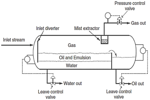
This forces the inlet mixture of oil and water to mix with the water continuous phase in the bottom of the vessel and rise through the oil/water interface. This process is called “water washing” and promotes the coalescence of water droplets that are entrained in the oil continuous phase. The inlet diverter assures that little gas is carried with the liquid, and the water wash assures that the liquid does not fall on top of the gas/oil or oil/water interface, mixing the liquid retained in the vessel and making control of the oil/water interface difficult. The liquid-collecting section of the vessel provides sufficient time so that the oil and emulsion form a layer or “oil pad” at the top. The free water settles to the bottom. The produced water flows from a nozzle in the vessel located upstream of the oil weir. An interface level controller senses the height of the oil/water interface. The controller sends a signal to the water dump valve, thus allowing the correct amount of water to leave the vessel so that the oil/water interface is maintained at the design height.
The gas flows horizontally and outs through a mist extractor (normally known as a demisting device) to a pressure control valve that maintains constant vessel pressure. The level of the gas/oil interface can vary from half the diameter to 75 % of the diameter depending on the relative importance of liquid/gas separation and what purpose the separator has. For example, degassers and produced water flash drums have very high liquid/ gas interfaces. However, the most common configuration is half full.
Figure 2 shows a typical configuration for a vertical three-phase separator. In the vertical separator, the flow enters the vessel through the side as in the horizontal separator and the inlet diverter separates the bulk of the gas. The gas moves upward, usually passing through a mist extractor to remove suspended mist, and then the dry gas flows out. A downcomer is required to transmit the liquid collected through the oil – gas interface so as not to disturb the oil-skimming action taking place.
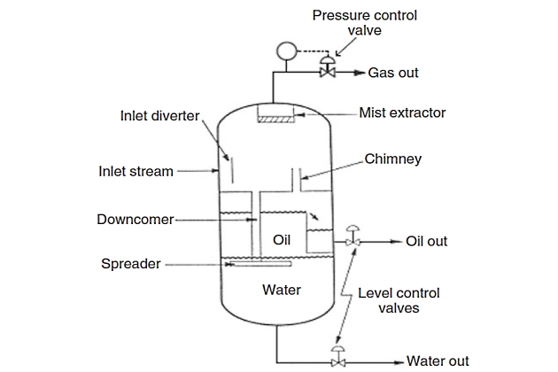
A chimney is needed to equalize gas pressure between the lower section and the gas section. The spreader or downcomer outlet is located at the oil – water interface. From this point as the oil rises any free water trapped within the oil phase separates out. The water droplets flow countercurrent to the oil. Similarly, the water flows downward and oil droplets trapped in the water phase tend to rise countercurrent to the water flow.
It should be clear that the principles of operation (such as oil/water interface level controlling) of three-phase vertical separators are the same as the three-phase horizontal separators described earlier. Essentially, the only difference is that horizontal separators have separation acting tangentially to flow, whereas vertical separators have separation acting parallel to flow. In the vertical separator, level control is not also critical, where the liquid level can fluctuate several inches without affecting operating efficiency. However, it can affect the pressure drop for the downcomer pipe (from the demister), therefore affecting demisting device drainage.
Separator Selection
There are no simple rules for separator selection. Sometimes, both configurations should be evaluated to decide which is more economical. The relative merits and common applications of vertical and horizontal separators are summarized by Manning and Thompson.
Horizontal separators
Horizontal separators are used most commonly in the following conditions.
- Large volumes of gas and/or liquids.
- High-to-medium gas/oil ratio (GOR) streams.
- Foaming crudes.
- Three-phase separation.
Advantages and disadvantages of these separators are as follow.
Advantages
- Require smaller diameter for similar gas capacity as compared to vertical vessels.
- No counterflow (gas flow does not oppose drainage of mist extractor).
- Large liquid surface area for foam dispersion generally reduces turbulence.
- Larger surge volume capacity.
Disadvantages
- Only part of shell available for passage of gas.
- Occupies more space unless “stack” mounted.
- Liquid level control is more critical.
- More difficult to clean produced sand, mud, wax, paraffin, etc.
Vertical Separators
These separators are used in the following conditions.
- Small flow rates of gas and/or liquids.
- Very high GOR streams or when the total gas volumes are low.
- Plot space is limited.
- Ease of level control is desired.
Advantages and disadvantages of these separators are as follow.
Advantages
- Liquid level control is not so critical.
- Have good bottom-drain and clean-out facilities.
- Can handle more sand, mud, paraffin, and wax without plugging.
- Less tendency for reentrainment.
- Has full diameter for gas flow at top and oil flow at bottom.
- Occupies smaller plot area.
Disadvantages
- Require larger diameter for a given gas capacity, therefore, most competitive for very low GOR or very high GOR or scrubber applications.
- Not recommended when there is a large slug potential.
- More difficult to reach and service top-mounted instruments and safety devices.
Gravity Separation Theory
Vapor/liquid separation is usually accomplished in three stages. The first stage, primary separation, uses an inlet diverter Inlet diverters are very old technology now and are used very rarely. Revamps in the north sea replace these inlet devices all the time, especially where the asset is producing more throughput than originally expected. If sized, incorrectly, inlet devices can cause serious separation issues due to droplet shatter. Schoepentoeters became the popular inlet device for a while, but these were designed for vertical separators and are therefore not always applicable. Cyclonic and distribution baffle inlet devices are more common nowadays.x to cause the largest droplets to impinge by momentum and then drop by gravity. The next stage, secondary separation, is gravity separation of smaller droplets as the vapor flows through the disengagement area. Gravity separation can be aided by utilizing distribution baffles that create an even velocity distribution in the fluid, thus allowing enhanced separation. The final stage is mist elimination, where the smallest droplets are coalesced on an impingement device, such as a mist pad or vane pack, followed by gravity settling of the larger formed droplets.
It will be interesting: Basic Info about Liquefied Petroleum Gas Vessels and Risks while Shipping a Cargo
In the gravity-settling section of the separators, the liquid drops will settle at a velocity determined by equating the gravity force (FB) on the drop with the drag force (FD) caused by its motion relative to the vapor continuous phase. When the drag force is equal to the buoyancy (gravity) force, the droplet acceleration is zero so that it moves at a constant velocity. This velocity is the terminal or free settling velocity, which is determined with respect to the following equations.
where:
- Dd – is drop diameter, ft;
- ρL – is liquid density, lbm/ft3;
- ρV – is vapor density, lbm/ft3;
- g – is gravitional constant, 32,174 ft/sec2;
- and gc – is conversion factor, 32,174 lbm-ft/sec2-lbf.
Also, the drag force on the droplet is given by:
where:
- CD – is drag coefficient, dimensionless;
- Ap – is projected drop area, ft2;
- (area of circle, not sphere);
- and Vd – is drop velocity, ft/sec.
Therefore, the terminal settling velocity of the liquid droplets (Vt) can be determined by equating Equations 1 and 2 as follow:
The drag coefficient can also be calculated as follows.
and
where:
- Dd – is in ft, densities are in lb/ft3;
- and viscosity – is in cP.
The droplet-settling velocity equation considers the escape of a drop from the continuous phase (e. g., the escape of an oil drop from the gas phase). For this purpose, the droplet-settling velocity must be greater than the superficial upward bulk vapor velocity, VV. Typically, the allowable vapor velocity is set between 0,75 Vt and Vt.
Equation 3 can be rearrenged as a Sauders and Brown type equation as follows:
where:
In practice, the Souders and Brown design coefficient (KSB) depends primarily on the type of mist extractor present, separator geometry, flow rates, and fluid properties. Therefore, KSB is usually determined from experiments. A well-known source of empirical KSB factors for mist pads is the GPSA Engineering Data Book. The GPSA’s K factors have been curve fitted and are given as:
Also, the factor KSB should be adjusted as follows:
- For most vapors under vacuum, KSB = 0,20.
- For glycols and amine solutions, multiply KSB values by 0,6-0,8.
- For compressor suction scrubbers and expander inlet separators, multiply KSB by 0,7-0,8.
Maximum terminal velocities calculated using the KSB factors are for separators normally having a wire-mesh mist extractor and should allow all liquid droplets larger than 10 µm to settle out of the gas. If no mist extractor is present, multiply KSB by 0,5.
It is often necessary to separate two immiscible liquids, light and heavy phases, and a vapor. A typical example in the petroleum industry is the separation of water, and a hydrocarbon liquid and vapor. For this system, the flow of rising light droplets in the heavy liquid phase or setteling heavy droplets in the light liquid phase is considered laminar and is governed by Stokes law:
where:
- Vt – is in inch/min, densities of light and heavy liquid phases (ρL, ρH) are in lb/ft3;
- viscosity – is in cP;
- and Dd – is in µm (1 µm = 3,28084 · 10-6 ft).
As can be seen from Raw Gas Transmission: Multiphase Flow, Hydrates, and Corrosion Challenges“Equations for two-phase gas/liquid density”, the settling velocity of a droplet is inversely proportional to the viscosity of the continous phase. Hence, it requires more time for the droplets to settle out of the continuous phase with greater viscosity. In practice, Vt is typically limited to 10 inch/min.
Design Considerations
The following factors must be determined before beginning separator design.
- Gas and liquids flow rates (minimum, average, and peak).
- Operating and design pressures and temperatures.
- Surging or slugging tendencies of the feed streams.
- Physical properties of the fluids, such as density, viscosity, and compressibility.
- Designed degree of separation (e. g., removing 100 % of particles greater than 10 µm).
Consideration for the future life of the field should also be included. For example, most north sea separators were designed for high oil cuts, but are now high water cuts, which produce a lot of nozzle problems.
In the separator design, it is also worthwhile to clarify two definitions: holdup and surge times. Holdup is defined as the time it takes to reduce the liquid level from normal (NLL) to low (LLL) while maintaining a normal outlet flow without feed makeup. Surge time is defined as the time it takes for the liquid level to rise from normal (NLL) to high (HLL) while maintaining a normal feed without any outlet flow. Holdup time is based on the reserve required to maintain good control and safe operation of downstream facilities, whereas surge time is usually based on requirements to accumulate liquid as a result of upstream or downstream variations or upsets, for e. g., slugs. In the absence of specific requirements, surge time may be taken as one-half of holdup time. Table 1 shows typical values of holdup time, tH, and surge time, tS.
| Table 1. Typical Values of Holdup and Surge Times | |||
|---|---|---|---|
| Service | tH, min | tS, min | |
| A. | Unit feed drum | 10 | 20 |
| B. | Separators | ||
| 1. Feed to column | 5 | 3 | |
| 2. Feed to other drum or tankage with pump or through exchange | 5 | 2 | |
| without pump | 2 | 1 | |
| 3. Feed to fired heater | 10 | 3 | |
Design Procedure
The initial design and calculation of gravity separators are discussed in many books and basic references. However, a more accurate and detailed sizing of two- and three-phase separators can be performed using the design methods developed by Svrcek and Monnery and Monnery and Svrcek, which have been well received by the industry worldwide.
These procedures are a result of a review of literature sources and accepted industrial design guidelines and allow the production facility engineer to choose the detailed sizing parameters of two- and three-phase separators.
This section attempts to address the basics of three-phase separator design and to provide step-by-step procedures for three-phase vapor/liquid/liquid separator design. To add a degree of conservatism to the design, the volume available in the heads is ignored. It is reasonably common nowadays for vessel sizing to be subcontracted out either directly to the vessel supplier or sometimes to the internals supplier.
Vertical Separators
For a three-phase vertical separator, the total height can be broken into different sections, as shown in Figure 3. The separator height is then calculated by adding the heights of these sections. If a mist eliminator pad is used, additional height is added.
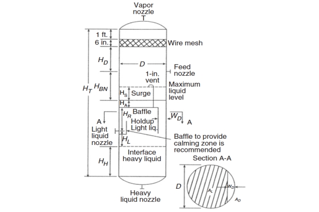
The calculations of diameter and height are detailed as follow.
1 Calculate the vertical terminal velocity using Equation 6 and set VV = 0,75 Vt for a conservative design.
2 Calculate the vapor volumetric flow rate:
3 Calculate the vessel internal diameter, Di:
If there is a mist eliminator, add 3-6 inch to Di to accommodate a supporting and round up to the next 6-inch increment to obtain D; if there is no mist eliminator, D = Di.
4 Calculate the settling velocity of the heavy liquid out of the light liquid using Equation 9 (with µ = µL).
5 Calculate the rising velocity of the light liquid out of the heavy liquid phase using Equation 9 (with µ = µH).
6 Calculate the light and heavy liquid volumetric flow rates, QLL and QHL:
7 Assume HL = 1 ft (minimum) and HH = 1 ft (minimum) and calculate the settling times for the heavy liquid droplets to settle (ts, HL) and for the light liquid droplets to rise (ts, LL) through this section, respectively, as:
where the settling velocity of heavy liquid droplets out of light liquid (VHL) and the rising velocity of light liquid droplets out of heavy liquid (VLL) are in inch/min.
8 If there is a baffle plate, calculate the area, AL, as:
where:
A – is vertical vessel cross-sectional area,
and AD is downcomer cross-sectional area, ft2.
In the equation just given, the larger value of AD that can be calculated from two following equations should be used.
where:
- baffle liquid load (G) will be obtained from Figure 4.
where:
- downcomer chord width (WD) – is assumed 4 inch.
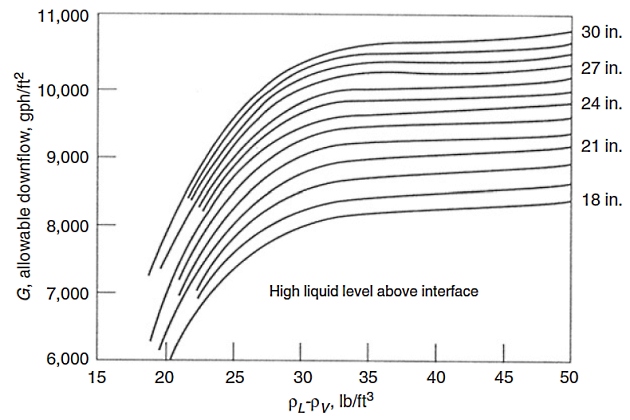
In Figure 4 the high liquid level above interface is equal to HL + HR, where the height from light liquid nozzle to baffle (HR) is assumed 9 inch as a minimum.
9 Calculate the residence time (tr) of each phase based on the volumes occupied by the light and heavy phases as:
If tr, LL < ts, HL or tr, HL < ts, LL, increase the diameter and repeat the procedure from step 7 (liquid separation is controlling). Note that AH = A.
10 Calculate HR based on the required holdup time (tH) as:
Check this value with that assumed in step 8 to ensure that the assumed value is reasonable. If surge is not specified, calculate the surge height (HS) based on surge time (tS):
where:
- the minimum HS is 6 inch.
11 Calculate the vessel total height (HT) as:
where:
- HA – is liquid level above baffle, which is 6 inch (minimum);
- and HBN – is liquid height from above baffle to feed nozzle, ft.
where:
- the nozzle diameter (DN) – is calculated using the following criterion:
- QM and ρM are volumetric flow rate and no-slip density of vapor/liquid mixture, respectively.
- HD – is disengagement height (ft) = 0,5D or a minimum of:
- 36 inch + ½ (DN); without mist eliminator.
- 24 inch + ½ (DN); with mist eliminator.
If a mist eliminator pad is used, additional height is added as shown in Figure 3.
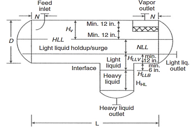
Horizontal Separator
There are different types of horizontal three-phase separators. However, the most common type includes a boot, as shown in Figure 5, which is a better design for the system of a small amount of heavy liquid (< 15 – 20 % of total liquid by weight) and a large amount of vapor. This section only presents a design procedure for this type of separator. Readers are referred to the original paper of Monnery and Svrcek for a detailed design of other types of horizontal three-phase separators.
The horizontal design procedure incorporates optimizing the diameter and length by minimizing the approximate weight of the shell and heads.
A stepwise procedure for designing horizontal three-phase separators with a boot is as follows.
1 Calculate the vapor volumetric flow rate, QV, using Equation 11.
2 Calculate the light and heavy liquid volumetric flow rates, QLL and QHL, per Equations 13 and 14.
3 Calculate the vertical terminal velocity, Vt, using Equation 6 and set VV = 0,75 Vt.
4 Select holdup and surge times from Table 1 and calculate the holdup and surge volumes, VH and VS, from the following equations (unless surge is otherwise specified, such as slug volume):
5 Obtain L/D from Table 2 and initially calculate the diameter according to
Then calculate the total cross-sectional area,
| Table 2. L/D Ratio Guidelines | |
|---|---|
| Vessel operating pressure (psig) | L/D |
| 0 < P ≤ 250 | 1,5 – 3,0 |
| 250 < P ≤ 500 | 3,0 – 4,0 |
| P > 500 | 4,0 – 6,0 |
7 Set the light liquid heights in the vessel and boot, HLLV and HLLB.
9 Calculate the minimum length to accommodate the liquid holdup/surge:
10 Calculate the liquid dropout time, φ, using the following equation:
11 Calculate the actual vapor velocity, VAV, as:
12 Calculate the minimum length required for vapor/liquid separation, L2, as:
13 If L1 < L2, then set L1 = L2 (vapor/liquid separation controls). This simply results in some extra holdup and residence time. If L1 ≪ L2, increase HV and recalculate AV and then repeat from step 9. If L1 > L2, the design is acceptable for vapor/liquid separation. If L1 ≫ L2, liquid holdup controls. L1 can only be reduced and L2 increased if HV is reduced. HV may only be reduced if it is greater than the minimum specified in step 6. With reduced HV, recalculate AV and repeat from step 9.
14 Calculate the settling velocity of the heavy liquid out of the light liquid phase, VHL, as:
where:
- KS – is obtained from Equation 10.
15 Calculate the settling time of the heavy liquid out of the light liquid phase as:
16 Calculate the residence time of the light liquid as:
This volume of light liquid ignores the light liquid volume in the boot.
17 If tr, LL < ts, HL, then increase the vessel length (liquid separation controls) as:
18 Calculate L/D. If L/D ≪ 1,5, then decrease D (unless it is already at a minimum) and if L/D ≫ 6,0, then increase D; repeat from step 5.
19 Calculate the wall thickness and surface area of the shell and heads, and approximate vessel weight according to Table 3.
| Table 3. Wall Thickness, Surface Area, and Approximate Vessel Weighta | ||
|---|---|---|
| Component | Wall thickness (inch) | Surface area (ft2) |
| Shell | πDL | |
| 2:1 elliptical heads | 1,09D2 | |
| Hemispherical heads | 1,571D2 | |
| Dished heads | 0,842D2 | |
| Approximate vessel weight | ||
| Note: The design pressure (P, psig) is typically either the operating pressure with 15 to 30 psi added to it or the operating pressure plus 10 %, whichever is greater. For the allowable stress, S, refer to ASME Pressure Vessel Code. The joint efficiency, E, ranges from 0,6 to 1,0. The corrosion allowance (σC) typically ranges from 1/16 to 1/8 inch. | ||
20 Increase or decrease the vessel diameter by 6-inch increments and repeat the calculations until L/D ranges from 1,5 to 6,0.
21 With the optimum vessel size (minimum weight), calculate the normal and high liquid levels (HNLL and HHLL) as:
Determine HNLL using Equation 19 from
(replacing WD with HNLL and ANLL with AD).
22 Design the heavy liquid boot. Set the height of the heavy liquid, HHL; calculate the rising velocity of the light liquid out of the heavy liquid phase (VLL) as:
Set boot velocity (VB) to 0,75 VLL and calculate the heavy liquid boot diameter, DB, as:
Then calculate the settling time of the light liquid (ts, LL) out of the heavy liquid phase using Equation 16.
23 Calculate the residence time of the heavy liquid (tr, HL) in the boot as:
If
then increase the boot diameter.
Practical Separator Design
The biggest development in recent years is the widespread recognition that the actual performance of a separator may fall far short of the theoretical performance due to the actual flow patterns within the vessel being far from the ideal (although strictly this is a “rediscovery“). It has, however, been helped by two visualization techniques – computational fluid dynamics (CFD) and physical modeling, which vividly show what can go wrong and how to correct it.
The most important areas to ensure a separator performs to design are as follow.
- Correct inlet nozzle sizing and a good inlet device (momentum breaker). The two main sorts are the “vane” inlet (schoepentoeter, or the many proprietary versions of this) and the cyclonic inlet.
- Primary fluid distribution-distribution plates to translate the reduced but still high velocities from the inlet device into quiescent flows in a liquid-liquid separator body, or distribution plates either side of a vane pack (downstream is best as upstream ones shatter droplets unnecessarily) or other gas demister.
- Intermediate fluid distribution when necessary (e. g., to align flow before entry to a plate pack or where a separator has an unusual shape or aspect ratio).
- Exit devices: vortex breakers and antiliquid – pickup details.
The methods of verifying performance “before” and “after” the introduction of good practice such as these internals are CFD and physical modeling, which uses dimensionless number similarity to model at a reduced scale, with air-water, air-oil-water, or gas-oil-water. The more advanced centers have pressure flow loops that can run on Hazards and Risks in Usage of Land Transport in Oil and Gas Industryoil and gas at pressure, but have the drawback that one cannot view what is happening inside the vessel in the way a perspective model allows.
Operating Problems
The following problems are occasionally occurred in the operation of separators.
Foamy Crudes
The major cause of foam in crude oil is the appearance of impurities, other than water, that are impractical to remove before the stream reaches the separator. Foam presents no problem within a separator if the internal design assures adequate time or sufficient coalescing surface for the foam to “break“. Foaming in a separating vessel is a threefold problem:
- Mechanical control of liquid level is aggravated because any control device must deal with three liquid phases, an emulsion is the third phase, instead of two-phases.
- Foam has a large volume-to-weight ratio. Therefore, it can occupy much of the vessel space that would otherwise be available in the liquid-collecting or gravity-settling sections.
- In an uncontrolled foam bank, it becomes impossible to remove separated gas or degassed oil from the vessel without entraining some of the foamy material in either the liquid or the gas outlets. Essentially as the foam is dispersed, it creates very small liquid droplets, which carry over.
It should be noted that the amount of foam is dependent on the pressure drop to which the inlet liquid is subjected, as well as the characteristics of the liquid at separator conditions. In some cases, the effect of temperature may be significant. Foam depressants will often be effective in increasing the capacity of a given separator. Foam can be reduced by:
- using a defoaming pack,
- using defoaming chemicals,
- and utilizing heat to break it down.
Paraffin
Coalescing plates in the liquid section and mesh pad mist extractors in the gas section are particularly prone to clogging by accumulations of paraffin waxes. Manways, handholes, and nozzles should be provided to allow steam, solvent, or other types of cleaning of the separator internals.
Also, the bulk temperature of the liquid should always be kept above the cloud point of the crude oil to prevent parraffin wax formation in the separators.
Sand
Sand can be very troublesome in separators by causing cutout of valve trim, plugging of separator internals, and accumulation in the bottom of the separator, thus leading to level control problems. Traditionally, sand has only been removed once it has collected in the main production separators. However, removal of sand upstream of these separators reduces sand problems to a minimum, giving substantial operational benefits.
Read also: General information and Rules for Ships carrying LNG and LPG
To meet these needs, the Mozley Wellspin desander has been developed to remove sand effectively in simple, compact systems based on solid/liquid hydro-cyclones, which remove the sand before it enters the separator. It should be noted that sand problems may be solved by using a filter or desanding cyclone before the separator; however, filters will quickly block in sandy service and are not often used.
Liquid Carryover and Gas Blowby
Liquid carryover occurs when free liquid escapes with the gas phase and can indicate high liquid level, damage to vessel internals, foam, improper design, plugged liquid outlets, or a flow rate that exceeds the design rate of the vessel. Gas blowby occurs when free gas escapes with the liquid phase and can be an indication of low liquid level, vortexing, or level control failure.
Emulsions
Emulsions can be particularly troublesome in the operation of three-phase separators. Over a period of time an accumulation of emulsified materials and/or other impurities usually will form at the interface of the water and oil phases. In addition to adverse effects on the liquid level control, this accumulation will also decrease the effective oil or water retention time in the separator, with a resultant decrease in water-oil separation efficiency. The addition of chemicals and/or heat often minimizes this difficulty. Frequently, it is possible to appreciably lower the settling time necessary for oil-water separation by either the application of heat in the liquid section of the separator (heat can be added through recycling) or the addition of deemulsifying chemicals.
Multistage Separation
To achieve good separation between gas and liquid phases and maximizing hydrocarbon liquid recovery, it is necessary to use several separation stages at decreasing pressures in which the well stream is passed through two or more separators arranged in series. The operating pressures are sequentially reduced, hence the highest pressure is found at the first separator and the lowest pressure at the final separator. In practice, the number of stages normally ranges between two and four, which depends on the gas/oil ratio (GOR) and the well stream pressure, where two-stage separation is usually used for low GOR and low well stream pressure, three-stage separation is used for medium to high GOR and intermediate inlet pressure, and four-stage separation is used for high GOR and a high pressure well stream. Note that three-stage separation usually represents the economic optimum, where it allows 2 to 12 % higher liquid recovery in comparison with two-stage separation and, in some cases, recoveries up to 25 % higher. To recover the gases fractions produced in the separators operating at medium pressure and low pressure, it is necessary to recompress them to the pressure of the high-pressure separator.
However, for an associated gas, recompression is sometimes considered too costly; hence the gas produced from the low-pressure separator may be flared.
It should be noted that the main objective of stage separation is to provide maximum stabilization to the resultant phases (gas and liquid) leaving the final separator, which means that the considerable amounts of gas or liquid will not evolve from the final liquid and gas phases, respectively.
The quantities of gas and liquid recovered at a given pressure are determined by equilibrium flash calculations using an appropriate equation of state (EOS). This helps optimize the value of pressure that is set for each separator. The pressures are often staged so that the ratio of the pressures in each stage is constant. Therefore, if the pressure in the first separator (which is normally fixed by specification or economics) and the pressure in the final separator (which will be near the atmospheric pressure) are known, the pressure in each stage can be determined.
Centrifugal Separators
In centrifugal or cyclone separators, centrifugal forces act on droplet at forces several times greater than gravity as it enters a cylindrical separator. This centrifugal force can range from 5 times gravity in large, low-velocity units to 2 000 times gravity in small, high-pressure units. Generally, centrifugal separators are used for removing droplets greater than 100 µm in diameter, and a properly sized centrifugal separator can have a reasonable removal efficiency of droplet sizes as low as 10 µm.
Centrifugal separators are also extremely useful for gas streams with high particulate loading. Such equipment has already been studied, however, a simple; compact, and lightweight gas-liquid cylindrical cyclone (GLCC) separator has been developed by Tulsa University that requires little maintenance and is easy to install and operate.
It will be interesting: Safety while Working on Marine Transport Over Water and Under Water
The compact dimensions, smaller footprint, and lower weight of the GLCC have a potential for cost savings to the industry, especially in offshore applications. Also, the GLCC reduces the inventory of hydrocarbons significantly, which is critical to environmental and safety considerations.
The GLCC separator, used mainly for bulk gas/liquid separation, can be designed for various levels of expected performance. Typical performance levels from the GLCC separator are 0,5-2,0 gallons of liquid per MMscf in the gas outlet and 0-5 % gas in the liquid outlet. More information on the design, control system studies, experimental investigations, and field applications of GLCC separators is discussed in greater detail by Gomez et al., Mohan and Shoham, and Wang et al.
Twister Supersonic Separator
The Twister supersonic separator is a unique combination of known physical processes, combining expansion, cyclonic gas/liquid separation, and recompression process steps in a compact, tubular device to condense and separate water and heavy hydrocarbons from Mastering Natural Gas Fundamentals Properties Sources and Transport Insightsnatural gas. Condensation and separation at supersonic velocity are key to achieving step-change reductions in both capital and operating costs. The residence time inside the Twister supersonic separator is only milliseconds, allowing hydrates no time to form and avoiding the requirement for hydrate inhibition chemicals.
Elimination of the associated chemical regeneration systems avoids harmful benzene, toluene, and xylene emissions to the environment or the expense of chemical recovery systems. The simplicity and reliability of a static device, with no rotating parts, which operates without chemicals, ensure a simple facility with a high availability suitable for unmanned operation in harsh and/or offshore environments. In addition, the compact and low weight Twister system design enables debottlenecking of existing space and weight-constrained platforms. The first commercial application at the Shell-operated B11 platform offshore Malaysia proves the technical and commercial maturity of a Twister supersonic separator, which is a major milestone toward the industry acceptance of this innovative technology.
However, the feasibility and benefits of this technology must be studied for a specific gas development. More information about the system design of the Twister supersonic separator is discussed in greater detail by Okimoto and Brouwer and Brouwer and Epsom.
Slug Catcher
Slug catchers are used at the terminus of Offshore terminal for transshipment of liquefied gasoffshore pipelines to catch large slugs of liquid in pipelines, to hold these slugs temporarily, and then to allow them to follow into downstream equipment and facilities at a rate at which the liquid can be handled properly. Slug catchers may be either a vessel or constructed of pipes. Pipe-type slug catchers are frequently less expensive than vessel type slug catchers of the same capacity due to thinner wall requirements of smaller pipe diameter. The manifold nature of multiple pipe-type slug catchers also makes possible the later addition of additional capacity by laying more parallel pipes. A schematic of a pipe-type slug catcher appears in Figure 6.
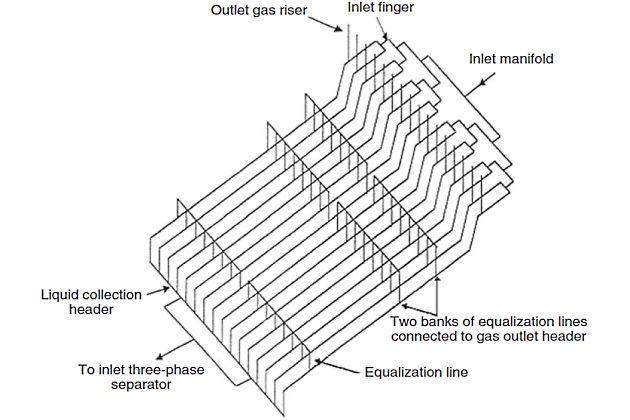
The general configuration consists of the following parts.
- Fingers with dual slope and three distinct sections: gas/liquid separation, intermediate, and storage sections.
- Gas risers connected to each finger at the transition zone between separation and intermediate sections.
- Gas equalization lines located on each finger. These lines are located within the slug storage section.
- Liquid header collecting liquid from each finger. This header will not be sloped and is configured perpendicular to the fingers.
Note that it has been assumed that all liquids (condensate and water) are collected and sent to an inlet three-phase separator, although it is possible to separate condensate and water at the fingers directly. When doing condensate/water separation at the slug catcher itself, we have to allow separately for the maximum condensate slug and the maximum water slug in order to ensure continuous level control.
Separation of the Gas Produced in Field from Unnecessary ComponentsSeparation of gas and liquid phases is achieved in the first section of the fingers. The length of this section promotes a stratified flow pattern and permits primary separation to occur. Ideally, liquid droplets, 600 µm and below, are removed from the gas disengaged into the gas risers, which are located at the end of this section. The length of the intermediate section is minimal such that there is no liquid level beneath the gas riser when the slug catcher is full, i. e., storage section completely full. This section comprises a change in elevation between the gas risers and the Cargo Storage System Concepts for Liquid Natural Gas Tanksstorage section that allows a clear distinction between liquid and gas phases.
The length of the storage section ensures that the maximum slug volume can be retained without liquid carryover in the gas outlet. During normal operations, the normal liquid level is kept at around the top of the riser from each finger into the main liquid collection header, which is equivalent to approximately a 5-min operation of the condensate stabilization units at maximum capacity.
Read also: Process of Liquefied Natural Gas regasification
As the finger type of slug catcher is defined as a piping configuration rather than a pressure vessel, it is not constrained to the same requirements as a normal vessel; however, due to its size, it will contain the majority of high-pressure hydrocarbon gas on the site. It is recommended that the slug catcher be depressurized automatically (for preventation of fire) as quickly as possible without imposing unusually high flow rates on the flare system.
Slug catcher design is dependent on several factors, of which the most important are pigging operation and changes in flow rates. Pigging can also be used as a means of limiting the required slug catcher size, where by pigging at frequent intervals, liquid inventory buildup in a pipeline can be reduced and the maximum slug size can be limited. However, a slug catcher size should be chosen on the basis of balancing the cost of frequent pigging operations and the capital reduction of smaller slug catchers.
Pigging requirements and ramp-up periods are determined by transient analysis once the steady-state liquid holdup of the pipeline is understood.
Generally, ramp-up rates are determined over the range of operating flow rates. Turndown flow rates are normally predetermined by the client with an overall processing philosophy. Detail information about the complete design of the finger-type slug catchers and other types of slug-catching configurations are discussed regularly with specific vendors.

- Acikgoz, M., Franca, F., and Lahey Jr, R. T., An experimental study of three-phase flow regimes. Int. J. Multiphase Flow 18(3), 327-336 (1992).
- Adewmi, M. A., and Bukacek, R. F., Two-phase pressure drop in horizontal pipelines. J. Pipelines 5, 1-14 (1985).
- Amdal, J., et al., “Handbook of Multiphase Metering.” Produced for The Norwegian Society for Oil and Gas Measurement, Norway (2001).
- Ansari, A. M., Sylvester, A. D., Sarica, C., Shoham, O., and Brill, J. P., A comprehensive mechanistic model for upward two-phase flow in wellbores. SPE Prod. Facilit. J. 143-152 (May 1994).
- API, “Computational Pipeline Monitoring”. API Publication 1130, 17, American Petroleum Institute, TX (1995a).
- API, “Evaluation Methodology for Software Based Leak Detection Systems”. API Publication 1155, 93, American Petroleum Institute, TX (1995b).
- API RP 14E, “Recommended Practice for Design and Installation of Offshore Production Platform Piping Systems”, 5th Ed., p. 23.
- Asante, B., “Two-Phase Flow: Accounting for the Presence of Liquids in Gas Pipeline Simulation”. Paper presented at 34th PSIG Annual Meeting, Portland, Oregon (Oct. 23–25, 2002).
- AsphWax’s Flow Assurance course, “Fluid Characterization for Flow Assurance”. AsphWax Inc., Stafford, TX (2003).
- Ayala, F. L., and Adewumi, M. A., Low-liquid loading multiphase flow in natural gas pipelines. ASME J. of Energy Res. Technol. 125, 284-293 (2003).
- Baillie, C., and Wichert, E., Chart gives hydrate formation temperature for natural gas. Oil Gas J. 85(4), 37-39 (1987).
- Baker, O., Design of pipelines for simultaneous flow of oil and gas. Oil Gas J. 53, 185 (1954).
- Banerjee, S., “Basic Equations”. Lecture presented at the Short Course on Modeling of Two-Phase Flow Systems, ETH Zurich, Switzerland (March 17-21, 1986).
- Barnea, D., A unified model for prediction flow pattern transitions for the whole range of pipe inclinations. Int. J. Multiphase Flow 13(1), 1-12 (1987).
- Barnea, D., and Taitel, Y., Stratified three-phase flow in pipes: Stability and transition. Chem. Eng. Comm. 141–142, 443-460 (1996).
- Battara, V., Gentilini, M., and Giacchetta, G., Condensate-line correlations for calculating holdup, friction compared to field data. Oil Gas J. 30, 148–52 (1985).
- Bay, Y., “Pipelines and Risers”, Vol. 5. Elsevier Ocean Engineering Book Series (2001).
- Beggs, H. D., and Brill, J. P., “A Study of Two-Phase Flow in Inclined Pipes”. JPT, 607-17; Trans., AIME, 255 (May 1973).
- Bendiksen, K., Brandt, I., Jacobsen, K. A., and Pauchon, C., “Dynamic Simulation of Multiphase Transportation Systems”. Multiphase Technology and Consequence for Field Development Forum, Stavanger, Norway (1987).
- Bendiksen, K., Malnes, D., Moe, R., and Nuland, S., The dynamic two-fluid model OLGA: Theory and application. SPE Prod. Eng. 6, 171-180 (1991).
- Bertola, V., and Cafaro, E., “Statistical Characterization of Subregimes in Horizontal Intermittent Gas/Liquid Flow”. Proc. the 4th International Conference on Multiphase Flow, New Orleans, LA (2001).
- Bjune, B., Moe, H., and Dalsmo, M., Upstream control and optimization increases return on investment. World Oil 223, 9 (2002).
- Black, P. S., Daniels, L. C., Hoyle, N. C., and Jepson, W. P., Studying transient multiphase flow using the pipeline analysis code (PLAC). ASME J. Energy Res. Technol. 112, 25-29 (1990).
- Bloys, B., Lacey, C., and Lynch, P., “Laboratory Testing and Field Trial of a New Kinetic Hydrate Inhibitor”. Proc. 27th Annual Offshore Technology Conference, OTC 7772, PP. 691-700, Houston, TX (1995).
- Bonizzi, M., and Issa, R. I., On the simulation of three-phase slug flow in nearly horizontal pipes using the multi-fluid model. Int. J. Multiphase Flow 29, 1719-1747 (2003).
- Boriyantoro, N. H., and Adewumi, M. A., “An Integrated Single-Phase/Two-Phase Flow Hydrodynamic Model for Predicting the Fluid Flow Behavior of Gas Condensate Pipelines”. Paper presented at 26th PSIG Annual Meeting, San Diego, CA (1994).
- Brauner, N., and Maron, M. D., Flow pattern transitions in two-phase liquid-liquid flow in horizontal tubes, Int. J. Multiphase Flow 18, 123-140 (1992).
- Brauner, N., The prediction of dispersed flows boundaries in liquid-liquid and gas-liquid systems, Int. J. Multiphase Flow 27, 885-910 (2001).
- Brill, J. P., and Beggs, H. D., “Two-Phase Flow in Pipes”, 6th Ed. Tulsa University Press, Tulsa, OK (1991).
- Bufton, S. A., Ultra Deepwater will require less conservative flow assurance approaches. Oil Gas J. 101(18), 66-77 (2003).
- Campbell, J. M., “Gas Conditioning and Processing”, 3rd Ed. Campbell Petroleum Series, Norman, OK (1992).
- Carroll, J. J., “Natural Gas Hydrates: A Guide for Engineers”. Gulf Professional Publishing, Amsterdam, The Netherlands (2003).
- Carroll, J. J., “An Examination of the Prediction of Hydrate Formation Conditions in Sour Natural Gas”. Paper presented at the GPA Europe Spring Meeting, Dublin, Ireland (May 19-21, 2004).
- Carson, D. B., and Katz, D. L., Natural gas hydrates. Petroleum Trans. AIME 146, 150-158 (1942).
- Chen, C. J., Woo, H. J., and Robinson, D. B., “The Solubility of Methanol or Glycol in Water-Hydrocarbon Systems”. GPA Research Report RR-117, Gas Processors Association, OK (March 1988).
- Chen, X., and Guo, L., Flow patterns and pressure drop in oil-air-water three-phase flow through helically coiled tubes. Int. J. Multiphase Flow 25, 1053-1072 (1999).
- Cheremisinoff, N. P., “Encyclopedia of Fluid Mechanics”, Vol. 3. Gulf Professional Publishing, Houston, TX (1986).
- Chisholm, D., and Sutherland, L. A., “Prediction of Pressure Gradient in Pipeline Systems during Two-Phase Flow”. Paper presented at Symposium on Fluid Mechanics and Measurements in Two-Phase Flow Systems, Leeds (Sept. 1969).
- Cindric, D. T., Gandhi, S. L., and Williams, R. A., “Designing Piping Systems for Two-Phase Flow”. Chem. Eng. Progress, 51-59 (March 1987).
- Collier, J. G., and Thome, J. R., “Convective Boiling and Condensation”, 3rd Ed. Clarendon Press, Oxford, UK (1996).
- Colson, R., and Moriber, N. J., Corrosion control. Civil Eng. 67(3), 58-59 (1997).
- Copp, D. L., “Gas Transmission and Distribution”. Walter King Ltd., London (1970).
- Courbot, A., “Prevention of Severe Slugging in the Dunbar 16 Multiphase Pipelines”. Paper presented at the Offshore Technology Conference, Houston, TX (May 1996).
- Covington, K. C., Collie, J. T., and Behrens, S. D., “Selection of Hydrate Suppression Methods for Gas Streams”. Paper presented at the 78th GPA Annual Convention, Nashville, TN (1999).
- Cranswick, D., “Brief Overview of Gulf of Mexico OCS Oil and Gas Pipelines: Installation, Potential Impacts, and Mitigation Measures”. U. S. Department of the Interior, Minerals Management Service, Gulf of Mexico OCS Region, New Orleans, LA (2001).
- Dhl, E., et al., “Handbook of Water Fraction Metering”, Rev. 1. Norwegian Society for Oil and Gas Measurements, Norway (June 2001).
- Decarre, S., and Fabre, J., Etude Sur La Prediction De l’Inversion De Phase. Revue De l’Institut Francais Du Petrole 52, 415-424 (1997).
- De Henau, V., and Raithby, G. D., A transient two-fluid model for the simulation of slug flow in pipelines. Int. J. Multiphase Flow 21, 335–349 (1995).
- Dukler, A. E., “Gas-Liquid Flow in Pipelines Research Results”. American Gas Assn. Project NX-28 (1969).
- Dukler, A. E., and Hubbard, M. G., “The Characterization of Flow Regimes for Horizontal Two-Phase Flow”. Proc. Heat Transfer and Fluid Mechanics Institute, 1, 100-121, Stanford University Press, Stanford, CA (1966).
- Eaton, B. A., et al., The prediction of flow pattern, liquid holdup and pressure losses occurring during continuous two-phase flow in horizontal pipelines. J. Petro. Technol. 240, 815-28 (1967).
- Edmonds, B., et al., “A Practical Model for the Effect of Salinity on Gas Hydrate Formation”. European Production Operations Conference and Exhibition, Norway (April 1996).
- Edmonds, B., Moorwood, R. A. S., and Szczepanski, R., “Hydrate Update”. GPA Spring Meeting, Darlington (May 1998).
- Esteban, A., Hernandez, V., and Lunsford, K., “Exploit the Benefits of Methanol”. Paper presented at the 79th GPA Annual Convention, Atlanta, GA (2000).
- Fabre, J., et al., Severe slugging in pipeline/riser systems. SPE Prod. Eng. 5(3), 299-305 (1990).
- Faille, I., and Heintze, E., “Rough Finite Volume Schemes for Modeling Two-Phase Flow in a Pipeline”. In Proceeding of the CEA.EDF.INRIA Course, INRIA Rocquencourt, France (1996).
- Fidel-Dufour, A., and Herri, J. S., “Formation and Dissociation of Hydrate Plugs in a Water in Oil Emulsion”. Paper presented at the 4th International Conference on Gas Hydrates, Yokohama, Japan (2002).
- Frostman, L. M., “Anti-aggolomerant Hydrate Inhibitors for Prevention of Hydrate Plugs in Deepwater Systems”. Paper presented at the SPE Annual Technical Conference and Exhibition, Dallas, TX (Oct. 1-4, 2000).
- Frostman, L. M., et al., “Low Dosage Hydrate Inhibitors (LDHIs): Reducing Total Cost of Operations in Existing Systems and Designing for the Future”. Paper presented at the SPE International Symposium on Oilfield Chemicals, Houston, TX (Feb. 5-7, 2003).
- Frostman, L. M., “Low Dosage Hydrate Inhibitor (LDHI) Experience in Deepwater”. Paper presented at the Deep Offshore Technology Conference, Marseille, France (Nov. 19-21, 2003).
- Fuchs, P., “The Pressure Limit for Terrain Slugging”. Proceeding of the 3rd BHRA International Conference on Multiphase Flow, Hague, The Netherlands (May 1987).
- Furlow, W., “Suppression System Stabilizes Long Pipeline-Riser Liquid Flows”. Offshore, Deepwater D&P, 48 + 166 (Oct., 2000).
- Giot, M., “Three-Phase Flow”, Chap. 7.2. McGraw-Hill, New York (1982).
- Goulter, D., and Bardon, M., Revised equation improves flowing gas temperature prediction. Oil Gas J. 26, 107-108 (1979).
- Govier, G. W., and Aziz, K., “The Flow of Complex Mixtures in Pipes”. Van Nostrand Reinhold Co., Krieger, New York (1972).
- GPSA Engineering Data Book, 11th Ed. Gas Processors Suppliers Association, Tulsa, OK (1998).
- Gregory, G. A., and Aziz, K., Design of pipelines for multiphase gas-condensate flow. J. Can. Petr. Technol. 28-33 (1975).
- Griffith, P., and Wallis, G. B., Two-phase slug flow. J. Heat Transfer Trans. ASME. 82, 307-320 (1961).
- Haandrikman, G., Seelen, R., Henkes, R., and Vreenegoor, R., “Slug Control in Flowline/Riser Systems”. Paper presented at the 2nd International Conference on Latest Advance in Offshore Processing, Aberdeen, UK (Nov. 9-10, 1999).
- Hall, A. R. W., “Flow Patterns in Three-Phase Flows of Oil, Water, and Gas”. Paper presented at the 8th BHRG International Conference on Multiphase Production, Cannes, France (1997).
- Hammerschmidt, E. G., Formation of gas hydrates in natural gas transmission lines. Ind. Eng. Chem. 26, 851-855 (1934).
- Hart, J., and Hamersma P. J. Correlations predicting frictional pressure drop and liquid holdup during horizontal gas-liquid pipe flow with small liquid holdup. Int. J. Multiphase Flow 15(6), 974-964 (1989).
- Hartt, W. H., and Chu, W., New methods for CP design offered. Oil Gas J. 102(36), 64-70 (2004).
- Hasan, A. R., Void fraction in bubbly and slug flow in downward two-phase flow in vertical and inclined wellbores, SPE Prod. Facil. 10(3), 172–176 (1995).
- Hasan, A. R., and Kabir, C. S., “Predicting Multiphase Flow Behavior in a Deviated Well”. Paper presented at the 61st SPE Annual Technical Conference and Exhibition, New Orleans, LA (1986).
- Hasan, A. R., and Kabir, C. S., Gas void fraction in two-phase up-flow in vertical and inclined annuli. Int. J. Multiphase Flow 18(2), 279-293 (1992).
- Hasan, A. R., and Kabir, C. S., Simplified model for oil/water flow in vertical and deviated wellbores. SPE Prod. Facil. 14(1), 56-62 (1999).
- Hasan, A. R., and Kabir, C. S., “Fluid and Heat Transfers in Wellbores”. Society of Petroleum Engineers (SPE) Publications, Richardson, TX (2002).
- Havre, K., and Dalsmo, M., “Active Feedback Control as the Solution to Severe Slugging”. Paper presented at the SPE Annual Technical Conference and Exhibition, New Orleans, LA (Oct. 3, 2001).
- Havre, K., Stornes, K., and Stray, H., “Taming Slug Flow in Pipelines”. ABB Review No. 4, 55-63, ABB Corporate Research AS, Norway (2000).
- Hedne, P., and Linga, H., “Suppression of Terrain Slugging with Automatic and Manual Riser Chocking”. Advances in Gas-Liquid Flows, 453-469 (1990).
- Hein, M., “HP41 Pipeline Hydraulics and Heat Transfer Programs.” PennWell Publishing Company, Tulsa, OK (1984).
- Henriot, V., Courbot, A., Heintze, E., and Moyeux, L., “Simulation of Process to Control Severe Slugging: Application to the Dunbar Pipeline”. Paper presented at the SPE Annual Conference and Exhibition, Houston, TX (1999).
- Hewitt, G. F., and Roberts, D. N., “Studies of Two-Phase Flow Patterns by Simultaneous X-ray and Flash Photography”. AERE-M 2159, HMSO (1969).
- Hill, T. H., Gas injection at riser base solves slugging, flow problems. Oil Gas J. 88(9), 88-92 (1990).
- Hill, T. J., “Gas-Liquid Challenges in Oil and Gas Production”. Proceeding of ASME Fluids Engineering Division Summer Meeting, Vancouver, BC, Canada (June 22-26, 1997).
- Holt, A. J., Azzopardi, B. J., and Biddulph, M. W., “The Effect of Density Ratio on Two-Phase Frictional Pressure Drop”. Paper presented at the 1st International Symposium on Two-Phase Flow Modeling and Experimentation, Rome, Italy (Oct. 9-11, 1995).
- Holt, A. J., Azzopardi, B. J., and Biddulph, M. W., Calculation of two-phase pressure drop for vertical up flow in narrow passages by means of a flow pattern specific models. Trans. IChemE 77(Part A), 7-15 (1999).
- Hunt, A., Fluid properties determine flow line blockage potential. Oil Gas J. 94(29), 62–66 (1996).
- IFE, “Mitigating Internal Corrosion in Carbon Steel Pipelines”. Institute of Energy Technology News, Norway (April 2000).
- Jansen, F. E., Shoham, O., and Taitel, Y., The elimination of severe slug-ging, experiments and modeling. Int. J. Multiphase Flow 22(6), 1055-1072 (1996).
- Johal, K. S., et al., “An Alternative Economic Method to Riser Base Gas Lift for Deepwater Subsea Oil/Gas Field Developments”. Proceeding of the Offshore Europe Conference, 487-492, Aberdeen, Scotland (9-12 Sept., 1997).
- Jolly, W. D., Morrow, T. B., O’Brien, J. F., Spence, H. F., and Svedeman, S. J., “New Methods for Rapid Leak Detection in Offshore Pipelines”. Final Report, SWRI Project No. 04-4558, SWRI (April 1992).
- Jones, O. C., and Zuber, N., The interrelation between void fraction fluctuations and flow patterns in two-phase flow Int. J. Multiphase Flow. 2, 273-306 (1975).
- Kang, C., Wilkens, R. J., and Jepson, W. P., “The Effect of Slug Frequency on Corrosion in High-Pressure, Inclined Pipelines”. Paper presented at the NACE International Annual Conference and Exhibition, Paper No. 96020, Denver, CO (March 1996).
- Katz, D. L., Prediction of conditions for hydrate formation in natural gases. Trans. AIME 160, 140–149 (1945).
- Kelland, M. A., Svartaas, T. M., and Dybvik, L., “New Generation of Gas Hydrate Inhibitors”. 70th SPE Annual Technical Conference and Exhibition, 529-537, Dallas, TX (Oct. 22-25, 1995).
- Kelland, M. A., Svartaas, T. M., Ovsthus, J., and Namba, T., A new class of kinetic inhibitors. Ann. N. Y. Acad. Sci. 912, 281-293 (2000).
- King, M. J. S, “Experimental and Modelling Studies of Transient Slug Flow”. Ph.D. Thesis, Imperial College of Science, Technology, and Medicine, London, UK (March 1998).
- Klemp, S., “Extending the Domain of Application of Multiphase Technology”. Paper presented at the 9th BHRG International Conference on Multiphase Technology, Cannes, France (June 16-18, 1999).
- Kohl, A. L., and Risenfeld, F. C., “Gas Purification.” Gulf Professional Publishing, Houston, TX (1985).
- Kovalev, K., Cruickshank, A., and Purvis, J., “Slug Suppression System in Operation”. Paper presented at the 2003 Offshore Europe Conference, Aberdeen, UK (Sept. 2-5, 2003).
- Kumar, S., “Gas Production Engineering”. Gulf Professional Publishing, Houston, TX (1987).
- Lagiere, M., Miniscloux, and Roux, A., Computer two-phase flow model predicts pipeline pressure and temperature profiles. Oil Gas J. 82-91 (April 9, 1984).
- Langner, et al., “Direct Impedance Heating of Deepwater Flowlines.” Paper presented at the Offshore Technology Conference (OTC), Houston, TX (1999).
- Lederhos, J. P., Longs, J. P., Sum, A., Christiansen, R. l., and Sloan, E. D., Effective kinetic inhibitors for natural gas hydrates. Chem. Eng. Sci. 51(8), 1221-1229 (1996).
- Lee, H. A., Sun, J. Y., and Jepson, W. P., “Study of Flow Regime Transitions of Oil-Water-Gas Mixture in Horizontal Pipelines”. Paper presented at the 3rd International Offshore and Polar Engng Conference, Singapore (June 6–11 1993).
- Leontaritis, K. J., “The Asphaltene and Wax Deposition Envelopes”. The Symposium on Thermodynamics of Heavy Oils and Asphaltenes, Area 16C of Fuels and Petrochemical Division, AIChE Spring National Meeting and Petroleum Exposition, Houston, TX (March 19-23, 1995).
- Leontaritis, K. J., “PARA-Based (Paraffin-Aromatic-Resin-Asphaltene) Reservoir Oil Characterization”. Paper presented at the SPE International Symposium on Oilfield Chemistry, Houston, TX (Feb. 18-21, 1997a).
- Leontaritis, K. J., Asphaltene destabilization by drilling/completion fluids. World Oil 218(11), 101-104 (1997b).
- Leontaritis, K. J., “Wax Deposition Envelope of Gas Condensates”. Paper presented at the Offshore Technology Conference (OTC), Houston, TX (May 4–7 1998).
- Lin, P. Y., and Hanratty, T. J., Detection of slug flow from pressure measurements. Int. J. Multiphase Flow 13, 13-21 (1987).
- Lockhart, R. W., and Martinelli, R. C., Proposed correlation of data for isothermal two-phase, two-component flow in pipes. Chem. Eng. Prog. 45, 39-48 (1949).
- Maddox, R. N., et al., “Predicting Hydrate Temperature at High Inhibitor Concentration”. Proceedings of the Laurance Reid Gas Conditioning Conference, 273-294, Norman, OK (1991).
- Mann, S. L., et al., “Vapour-Solid Equilibrium Ratios for Structure I and II Natural Gas Hydrates”. Proceedings of the 68th GPA Annual Convention, 60-74, San Antonio, TX (March 13-14, 1989).
- Martinelli, R. C., and Nelson, D. B., Prediction of pressure drop during forced circulation boiling of water. Trans. ASME 70, 695 (1948).
- Masella, J. M., Tran, Q. H., Ferre, D., and Pauchon, C., Transient simulation of two-phase flows in pipes. Oil Gas Sci. Technol. 53(6), 801–811 (1998).
- McCain, W. D., “The Properties of Petroleum Fluids”, 2nd Ed. Pennwell Publishing Company, Tulsa, OK (1990).
- McLaury, B. S., and Shirazi, S. A., An alternative method to API RP 14E for predicting solids erosion in multiphase flow. ASME J. Energy Res. Technol. 122, 115-122 (2000).
- McLeod, H. O., and Campbell, J. M., Natural gas hydrates at pressure to 10,000 psia. J. Petro. Technol. 13, 590-594 (1961).
- Mehta, A. P., and Sloan, E. D., “Structure H Hydrates: The State-of-the-Art”. Paper presented at the 75th GPA Annual Convention, Denver, CO (1996).
- Mehta, A., Hudson, J., and Peters, D., “Risk of Pipeline Over-Pressurization during Hydrate Remediation by Electrical Heating”. Paper presented at the Chevron Deepwater Pipeline and Riser Conference, Houston, TX (March 28-29, 2001).
- Mehta, A. P., Hebert, P. B., and Weatherman, J. P., “Fulfilling the Promise of Low Dosage Hydrate Inhibitors: Journey from Academic Curiosity to Successful Field Implementations”. Paper presented at the 2002 Offshore Technology Conference, Houston, TX (May 6-9, 2002).
- Minami, K., “Transient Flow and Pigging Dynamics in Two-Phase Pipelines”. Ph.D. Thesis, University of Tulsa, Tulsa, OK (1991).
- Mokhatab, S., Correlation predicts pressure drop in gas-condensate pipelines. Oil Gas J. 100(4), 66-68 (2002a).
- Mokhatab, S., New correlation predicts liquid holdup in gas-condensate pipelines. Oil Gas J. 100(27), 68-69 (2002b).
- Mokhatab, S., Model aids design of three-phase, gas-condensate transmission lines. Oil Gas J. 100(10), 60-64 (2002c).
- Mokhatab, S., Three-phase flash calculation for hydrocarbon systems containing water. J. Theor. Found. Chem. Eng. 37(3), 291-294 (2003).
- Mokhatab, S., Upgrade velocity criteria for sizing multiphase pipelines. J. Pipeline Integrity 3(1), 55-56 (2004).
- Mokhatab, S., “Interaction between Multiphase Pipelines and Down-stream Processing Plants”. Report No. 3, TMF3 Sub-Project VII: Flexible Risers, Transient Multiphase Flow (TMF) Program, Cranfield University, Bedfordshire, England (May 2005).
- Mokhatab, S., “Explicit method predicts temperature and pressure profiles of gas-condensate pipelines”. Accepted for publication in Energy Sources: Part A (2006a).
- Mokhatab, S., Severe slugging in a catenary-shaped riser: Experimental and simulation studies”. Accepted for publication in J. Petr. Sci. Technol. (2006b).
- Mokhatab, S., Dynamic simulation of offshore production plants. Accepted for publication in J. Petr. Sci. Technol. (2006c).
- Mokhatab, S., Severe slugging in flexible risers: Review of experimental investigations and OLGA predictions. Accepted for publication in J. Petro. Sci. Technol. (2006d).
- Mokhatab, S., and Bonizzi, M., “Model predicts two-phase flow pressure drop in gas-condensate transmission lines”. Accepted for publication in Energy Sources: Part A (2006).
- Mokhatab, S., Towler, B. F., and Purewal, S., A review of current technologies for severe slugging remediation”. Accepted for publication in J. Petro. Sci. Technol. (2006a).
- Mokhatab, S., Wilkens, R. J., and Leontaritis, K. J., “A Review of strategies for solving gas hydrate problems in subsea pipelines”. Accepted for publication in Energy Sources: Part A (2006b).
- Molyneux, P., Tait, A., and Kinving, J., “Characterization and Active Control of Slugging in a Vertical Riser”. Proceeding of the 2nd North American Conference on Multiphase Technology, 161–170, Banff, Canada (June 21–23, 2000).
- Moody, L. F., Friction factors for pipe flow. Trans. ASME 66, 671–684 (1944).
- Mucharam, L., Adewmi, M. A., and Watson, R., Study of gas condensation in transmission pipelines with a hydrodynamic model. SPE J. 236–242 (1990).
- Muhlbauer, K. W., “Pipeline Risk Management Manual”, 2nd Ed. Gulf Professional Publishing, Houston, TX (1996).
- Narayanan, L., Leontaritis, K. J., and Darby, R., “A Thermodynamic Model for Predicting Wax Precipitation from Crude Oils”. The Symposium of Solids Deposition, Area 16C of Fuels and Petro-chemical Division, AIChE Spring National Meeting and Petroleum Exposition, Houston, TX (March 28-April 1, 1993).
- Nasrifar, K., Moshfeghian, M., and Maddox, R. N., Prediction of equilibrium conditions for gas hydrate formation in the mixture of both electrolytes and alcohol. Fluid Phase Equilibria 146, 1–2, 1–13 (1998).
- National Association of Corrosion Engineers, “Sulfide Stress Cracking Resistant Metallic Materials for Oil Field Equipment”. NACE Std MR-01-75 (1975).
- Ng, H. J., and Robinson, D. B., The measurement and prediction of hydrate formation in liquid hydrocarbon-water systems. Ind. Eng. Chem. Fund. 15, 293-298 (1976).
- Nielsen, R. B., and Bucklin, R. W., Why not use methanol for hydrate control? Hydrocarb. Proc. 62(4), 71-78 (1983).
- Nyborg, R., Corrosion control in oil and gas pipelines. Business Briefing Exploration Prod. Oil Gas Rev. 2, 79-82 (2003).
- Oram, R. K., “Advances in Deepwater Pipeline Insulation Techniques and Materials”. Deepwater Pipeline Technology Congress, London, UK (Dec. 11–12, 1995).
- Oranje, L., Condensate behavior in gas pipelines is predictable. Oil Gas J. 39 (1973).
- Osman, M. E., and El-Feky, S. A., Design methods for two-phase pipelines compared, evaluated. Oil Gas J. 83(35), 57-62 (1985).
- Palermo, T., Argo, C. B., Goodwin, S. P., and Henderson, A., Flow loop tests on a novel hydrate inhibitor to be deployed in North Sea ETAP field. Ann. N. Y. Acad. Sci. 912, 355–365, (2000).
- Pan, L., “High Pressure Three-Phase (Gas/Liquid/Liquid) Flow”. Ph. D. Thesis, Imperial College, London (1996).
- Patault, S., and Tran, Q. H., “Modele et Schema Numerique du Code TACITE-NPW”. Technical Report 42415, Institut Francais du Petrole, France (1996).
- Pauchon, C., Dhulesia, H., Lopez, D., and Fabre, J., “TACITE: A Comprehensive Mechanistic Model for Two-Phase Flow”. Paper presented at the 6th BHRG International Conference on Multiphase Production, Cannes, France (1993).
- Pauchon, C., Dhulesia, H., Lopez, D., and Fabre, J., “TACITE: A Transient Tool for Multiphase Pipeline and Well Simulation”. Paper presented at the SPE Annual Technical Conference and Exhibition, New Orleans, LA (1994).
- Peng, D., and Robinson, D. B., A new two-constant equation of state. Ind. Eng. Chem. Fundam. 15(1), 59-64 (1976).
- Petalas, N., and Aziz, K., A mechanistic model for multiphase flow in pipes. J. Can. Petr. Technol. 39, 43-55 (2000).
- Polignano, R., Value of glass-fiber fabrics proven for bituminous coatings. Oil Gas J. 80(41), 156–158, 160 (1982).
- Pots, B. F. M., et al., “Severe Slug Flow in Offshore Flowline/Riser Systems”. Paper presented at the SPE Middle East Oil Technical Conference and Exhibition, Bahrain (March 11–14, 1985).
- Rajkovic, M., Riznic, J. R., and Kojasoy, G., “Dynamic Characteristics of Flow Pattern Transitions in Horizontal Two-Phase Flow”. Proc. 2nd European Thermal Science and 14th UIT National Heat Transfer Conference, 3, 1403–1408, Edizioni ETS, Pisa, Italy (1996).
- Ramachandran, S., Breen, P., and Ray, R., Chemical programs assure flow and prevent corrosion in deepwater facilities and dlowlines. InDepth 6, 1 (2000).
- Rhodes, K. I., Pipeline protective coatings used in saudi Arabia. Oil Gas J. 80(31), 123–127 (1982).
- Ripmeester, J. A., Tse, J. S., Ratcliffe, C. J., and McLaurin, G. E., Nature 135, 325 (1987).
- Sagatun, S. I., Riser slugging: A mathematical model and the practical consequences. SPE Product. Facil. J. 19(3), 168–175 (2004).
- Salama, M. M., An alternative to API 14E erosional velocity limits for sand-laden fluids. ASME J. Energy Res. Technol. 122, 71–77 (2000).
- Samant, A. K., “Corrosion Problems in Oil Industry Need More Attention”. Paper presented at ONGC Library, Oil and Natural Gas Corporation Ltd. (Feb. 2003).
- Sandberg, C., Holmes, J., McCoy, K., and Koppitsch, H., The application of a continues leak detection system to pipelines and associated equipment. IEEE Transact. Indust. Appl. 25, 5 (1989).
- Sarica, C., and Shoham, O., A simplified transient model for pipeline/riser systems. Chem. Engi. Sci. 46(9), 2167–2179 (1991).
- Sarica, C., and Tengesdal, J. Q., A New Technique to Eliminate Severe Slugging in Pipeline/Riser Systems”. Paper presented at the 75th SPE Annual Technical Conference and Exhibition, Dallas, TX (Oct. 1–4, 2000).
- Schmidt, Z., “Experimental Study of Two-Phase Slug Flow in a Pipeline-Riser System.” Ph.D. Dissertation, University of Tulsa, Tulsa, OK (1977).
- Schmidt, Z., Brill, J. P., and Beggs, D. H., Experimental study of severe slugging in a two-phase flow pipeline-riser system. SPE J. 20, 407–414 (1980).
- Schmidt, Z., Doty, D. R., and Dutta-Roy, K., Severe slugging in offshore pipeline-riser systems. SPE J. 27–38 (1985).
- Schweikert, L. E., Tests prove two-phase efficiency for offshore pipeline. Oil Gas J. 39-42 (1986).
- Scott, S. L., Brill, J. P., Kuba, G. E., Shoham, K. A., and Tam, W., “Two-Phase Flow Experiments in the Prudhoe Bay Field of Alaska”. Paper presented at the Multiphase Flow Technology and Consequences for Field Development Conference, 229–251, Stavanger, Norway (1987).
- Shoham, O., “Flow Pattern Transitions and Characterization in Gas-Liquid Two Phase Flow in Inclined Pipes”. Ph. D. Thesis, Tel-Aviv University, Ramat-Aviv, Israel (1982).
- Sinquin, A., Palermo, T., and Peysson, Y., Rheological and flow properties of gas hydrate suspensions. Oil Gas Sci. Technolo. Rev. IFP. 59(1), 41–57 (2004).
- Sloan, E. D., Jr., Natural gas hydrates. J. Petro. Technol. 43, 1414 (1991).
- Sloan, E. D., Jr., “Clathrate Hydrates of Natural Gases”, 2nd Ed. Dekker, New York (1998).
- Sloan, E. D., Jr., “Hydrate Engineering”. SPE Monograph, 21, Society of Petroleum Engineers (SPE) Publications, Richardson, TX (2000).
- Smart, J., A method for calculating the corrosion allowance for deepwater pipelines and risers. J. Pipeline Integrity 73 (2001).
- Soldati, A., Paglianti, A., and Giona, M., Identification of two-phase flow regimes via diffusional analysis of experimental time series. Exp. Fluids 21, 151–160 (1996).
- Son, V. K., and Wallace, C., “Reclamation/Regeneration of Glycols Used for Hydrate Inhibition”. Paper presented at the 12th Annual Deep Offshore Technology Conference and Exhibition, New Orleans, LA (Nov. 7–9, 2000).
- Sotberg, T., and Bruschi, R., “Future Pipeline Design Philosophy-Framework”. Paper presented at the 11th International Conference on Offshore Mechanics and Arctic Engineering, Calgary, AB, Canada (1992).
- Storkaas, E., Alstad, V., and Skogestad, S., “Stabilization of Desired Flow Regimes in Pipelines”. Paper presented at the AIChE Annual Meeting, Reno, NV (2001).
- Strommen, R. D., Horn, H., and Wold, K. R., New technique monitors pipeline corrosion, cracking. Oil Gas J. 91(52), 88–92 (1993).
- Taitel, Y., Stability of severe slugging. Int. J. Multiphase Flow 12(2), 203–217 (1986).
- Taitel, Y., “Flow Pattern Transition in Two-Phase Flow.” Paper presented at the 9th International Heat Transfer Conference, Jerusalem (1990).
- Taitel, Y., Barnea, D., and Brill, J. P., Stratified three-phase flow in pipes. Int. J. Multiphase Flow. 21(1), 53-60 (1995).
- Taitel, Y., Barnea, D., and Dukler, A. E., Modeling flow pattern transitions for steady upward gas-liquid flow in vertical tubes. AIChE J. 26(3), 345–354 (1980).
- Taitel, Y., and Dukler, A. E., A model for predicting flow regime transitions in horizontal and near horizontal gas-liquid flow. AIChE J. 22(1), 47 (1976).
- Taitel, Y., Shoham, O., and Brill, J. P., Simplified transient solution and simulation of two-phase flow in pipelines. Chem. Eng. Sci. 44(6), 1353–1359 (1989).
- Tek, M. R., Multiphase flow of water, oil, and natural gas through vertical flow strings. Journal of Petroleum Technology (JPT), 1029–1036 (1961).
- Tin, V., “Severe Slugging in Flexible Risers”. Proceeding of the 5th BHRG International Conference on Multiphase Production, 507–525, Cannes, France (1991).
- Tiratsoo, J. N. H., “Pipeline Pigging Technology”, 2nd Ed. Gulf Professional Publishing, Houston, TX (1992).
- Towler, B. F., and Mokhatab, S., Quickly estimate hydrate formation conditions in natural gases. Hydrocarb. Proc. 84(4), 61–62 (2005).
- Trekell, R. E., and Campbell, J.M., “Prediction of the Behavior of Hydro-carbon Clathrate Solutions”. Proceedings of the 151st Meeting of American Chemical Society, Petroleum Chemistry Division, 61, Pittsburgh, PA (March 1966).
- Uhl, A. E., “Steady Flow in Gas Pipelines”. IGT Report No. 10, American Gas Association (AGA), New York, (1965).
- Uhlig, H. H., and Revie, R. W., “Corrosion and Corrosion Control”, 3rd Ed. Wiley, New York (1985).
- Ullah, M. R., A comprehensive assessment of the performance of dry-gas methods for predicting the occurrence of wet-gas flow conditions. J. Pipelines 6 (1987).
- Van Hout, R., Shemer, L., and Barnea, D., Spatial distribution of void fraction within the liquid slug and some other related slug parameters. Int. J. Multiphase Flow 18, 831–845 (1992).
- Varughese, K., In-situ pipeline rehabilitation techniques, equipment improved. Oil Gas J. 91(25), 54–57 (1993).
- Verley, R., et al., “Wall Thickness Design for High Pressure Offshore Gas Pipelines”. Paper presented at the 13th International Conference on Offshore Mechanics and Arctic Engineering, Houston, TX (Feb. 27–March 3, 1994).
- Wallis, G. B., “One Dimensional Two-Phase Flow”. McGraw-Hill, New York (1969).
- Wilkens, R. J., “Prediction of the Flow Regime Transitions in High Pressure, Large Diameter, Inclined Multiphase Pipelines”. Ph.D. Thesis, Ohio University, Athens, OH (1997).
- Wilkens, R. J., Flow assurance. In “Fluid Flow Handbook” (J. Saleh, ed.), Chapter 29. McGraw-Hill, New York (2002).
- Xiao, J. J., Shoham, O., and Brill, J. P., “A Comprehensive Mechanistic Model for Two-Phase Flow in Pipelines”. Paper presented at the 65th SPE Annual Technical Conference and Exhibition, New Orleans, LA (Sept. 23–26, 1990).
- Xiao, J. J., and Shoup, G., Sizing wet-gas pipelines and slug catchers with steady-state multiphase flow simulations. ASME J. Energy Res. Technol. 120, 106–110 (1998).
- Yeung, H. C., and Lima, P. C. R., Modeling of pig assisted production methods. ASME J. Energy Res. Technol. 124, 8–13 (2002).
- Yocum, B. T., “Offshore Riser Slug Flow Avoidance: Mathematical Model for Design and Optimization”. Paper presented at the SPE London Meeting, London, UK (1973).
- Zhang, H.-Q., Wang, Q., Sarica, C., and Brill, J. P., Unified model for gas-liquid pipe flow via slug dynamics. 1. Model development. ASME J. Energy Res. Technol. 125(4), 266–273 (2003).
- Zuo, J. Y., and Zhang, D. D., “Gas Hydrate Formation in Aqueous Solutions Containing Methanol and Electrolytes”. Proceedings of the Laurance Reid Gas Conditioning Conference, 191–198, Norman, OK (Feb. 21–24, 1999).
Did you find mistake? Highlight and press CTRL+Enter