Coalescer Technology is fundamental to achieving high-purity fluid streams across numerous industrial sectors, including petrochemical refining, natural gas processing, and water treatment. These advanced devices are engineered to separate tiny liquid droplets and aerosols from a continuous phase, be it a gas or another liquid. The core principle involves the merging – or coalescence – of sub-micron particles into drops large enough to be separated by gravitational or inertial forces. High-efficiency systems often utilize specialized fibrous media, such as borosilicate microfibers, designed with a gradient density to maximize the capture and subsequent growth of these dispersed droplets.
- High-Effeciency Liquid-Gas Coalescers
- Aerosols
- Coalescer Construction/Operation Principles
- Modeling the Liquid/Gas Coalescer
- Coalescer Performance/Operational Limits
- Liquid/Gas Coalescer Applications
- High-Efficiency Liquid-Liquid Coalescers
- Emulsions
- Coalescer Principles and Materials of Construction
- Coalescer Mechanism of Operation
- Liquid/Liquid Coalescer Performance
- Limitations of Using Coalescers
- Applications
This technology is critical for both removing liquid aerosols from gas streams and breaking stable liquid-liquid emulsions. Successful separation relies heavily on factors like the material’s wetting characteristics, the continuous phase viscosity, and proper vessel design to prevent re-entrainment. The ongoing development of coalescer media and modeling techniques continues to enhance process efficiency, product quality, and equipment protection from harmful contamination.
High-Effeciency Liquid-Gas Coalescers
Aerosols in gas streams can often be less than 5 µm in size and require the use of special separation equipment. High-efficiency liquid-gas coalescers have been applied effectively for the removal of fine aerosols in Environmental aspects in Liquefied Natural Gas productiongas production, processing, and transmission. Coalescers are typically constructed as cartridges that use pleated glass fiber media supported by a metal core. The coalescer cartridges are then placed in a housing that controls the inlet/outlet gas velocities to ensure good separation and prevent any reentrainment of liquids. Coalescer media contain a much finer pore structure and larger surface area as compared to traditional separators that often use mesh pads or vane pack internals.
Aerosols
Aerosols are formed by three mechanisms:
- condensation,
- atomization,
- and entrainment.
The relative sizes produced by these formation mechanisms are given in Figure 1.
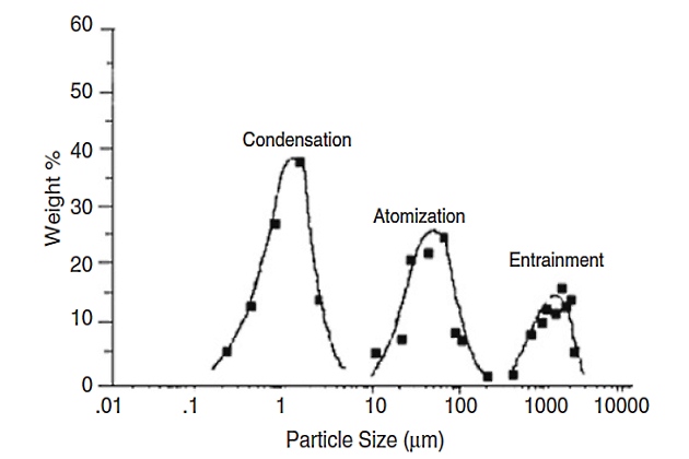
Aerosols formed by condensation of a vapor into a liquid are the smallest and most difficult to remove contaminants, having a size distribution in the range of 0,2 to 5 µm. Atomization creates aerosol drops by breaking up larger liquid drops through mechanical shear, such as passing through a constriction in a valve under a high velocity. Atomization forms aerosols in the size range of 10 to 200 µm. Entrainment involves the movement of liquid slugs along pipelines, where the liquid drop sizes are very large, from 500 to 5 000 µm. All three types of aerosol liquids are commonly found in gas systems. High-efficiency liquid-gas coalescers can effectively remove the fine aerosols created by the condensation mechanism.
Coalescer Construction/Operation Principles
High-efficiency liquid–gas coalescers are generally constructed from glass fibers, as this material allows for a fine porous structure with fiber diameters of a few micrometers. The small pore size is needed to achieve greater capture and separation of these small aerosols. The primary rationale for the use of high-efficiency coalescers is that significant aerosol contaminant exists in plants that are in the submicrometer and low micrometer size range. This type of liquid-gas coalescer can operate at significantly lower flow rates than the initial design flow rate and therefore can tolerate a high turndown ratio. This is due to the separation mechanisms for coalescing, which are primarily diffusion and direct interception, unlike vane separators and mesh pads that rely heavily on inertial separation principles. This allows the high-efficiency liquid/gas coalescer systems a greater degree of flexibility and they can operate at peak performance even for high turndown ratios (reduced flow rates) that can occur during commonly encountered partial plant shutdowns and upset conditions.
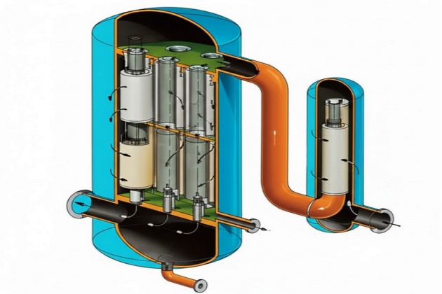
Use of a surface treatment on high-performance vertical liquid/gas coalescer cartridge systems has been proven to enhance performance significantly by allowing higher flow rates or smaller housing diameters compared to untreated coalescers. The surface treatment alters the properties of the coalescer medium so that it will not wet out with oil- or water-based fluids. The treatment has also been found to extend the service of the coalescer by reducing fouling and also to lower the saturated pressure drop. A Pall vertical high-efficiency liquid/gas coalescer system is depicted in Figure 2.
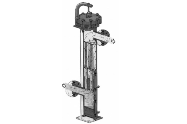
The inlet gas with liquid aerosol contamination first enters at the bottom of the housing into a first-stage knockout section. Here any slugs or larger size droplets (approximately >300 µm) are removed by gravitational settling. The gas then travels upward through a tube sheet and flows radially from the inside of the cartridges through the coalescer medium to the annulus. The inlet aerosol distribution is in the size range of 0,1-300 µm and, after passing through the coalescer medium, is transformed to enlarged coalesced droplets in the size range of 0,5-2,2 mm.
The advantage of flowing from the inside to the outside of the coalescer cartridge is that the gas velocity can be adjusted more easily in the annulus by selecting the optimum housing diameter to prevent reentrainment of coalesced droplets.
As the gas leaves the coalescer cartridge and travels upward in the annulus it contributes to the total flow, thereby increasing the annular velocity. The annular velocity is modeled as a linear function with vertical distance, and the annular velocity is zero at the bottom of the cartridge and increases to a maximum value at the top of the cartridge.
Once the coalesced droplets are formed, they immediately drain vertically downward in the coalescer medium pack. The surface treatment enhances this drainage greatly, and as a direct consequence of the treatment, the coalesced droplets are shielded from the upward gas flow in the annulus in the upper two-thirds section of the coalescer cartridge. The coalesced droplets are first exposed to the annular gas flow when they appear on the external face of the coalescer medium pack at the bottom third of the coalescer cartridge (see Figure 3).
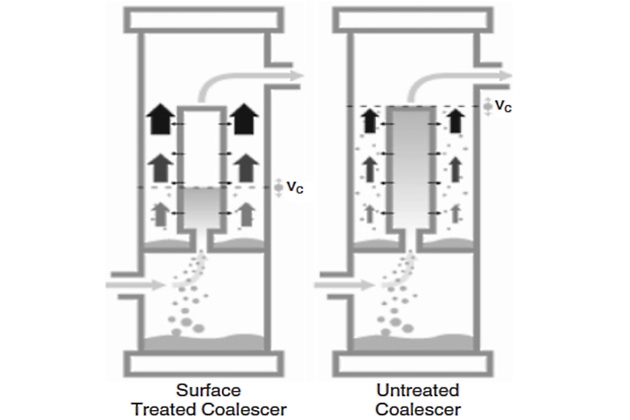
Once the coalesced droplets are released to the annular space they are subject to the force of the upward-flowing gas. The trajectory of the coalesced droplets is modeled on a force balance between gravity settling and the drag force created by the gas flow past the droplets. This analysis leads to the calculation of a critical annular velocity for reentrainment.
It will be interesting: LNGC Fatigue Assessment and Heating System
Due to the surface treatment, there are minimal coalesced droplets present in the annulus above the drainage point at the bottom third of the coalescer cartridge. For a coalescer cartridge that is not specially surface treated, the coalesced liquids are present throughout the length of the coalescer in the annulus space, and the critical annular velocity for reentrainment is given for the top of the element (see Figure 3). For the treated coalescer, it is allowable to have annular velocities greater than the critical value for reentrainment in the portion of the annulus space where there are no liquids present. This allows the maximum annular velocity at the top of the coalescer cartridge to be about three times the critical reentrainment value needed at the vertical position of the lower one-third of the cartridge height where liquids are present.
Therefore, the maximum annular velocity at the top of the coalescer cartridge is found to be about three times greater than the value for an untreated coalescer. The annular area is determined using the maximum allowable annular velocity and is designed to be of sufficient size to prevent reentrainment and as small as possible to minimize the housing diameter.
Modeling the Liquid/Gas Coalescer
The modeling of the liquid/gas coalescer system can be divided into two basic aspects for performance: media velocity and annular velocity. The other consideration to be taken into account is pressure drop. The pressure drop for a given system can be decreased by using more coalescer elements.
Media Velocity
The media velocity (Vmed) is defined as the actual flow rate divided by the coalescer filter area:
where:
- N – is number of coalescers;
- Amed – is media area for one coalescer;
- and Qa – is actual system flow rate at system conditions and is obtained from the standard system flow rate (Qs) as:
where:
- SG – is gas-specific gravity;
- ρAir, stp – is density of air at standard temperature and pressure;
- and ρG – is density of gas at system conditions.
The media velocity is not the actual velocity through the open pores of the media, but rather an average by convention over the combined pore area and solid matrix area in the spatial plane normal to the flow direction.
The maximum media velocity for a coalescer construction is related to a number of factors intrinsic to the particular coalescer design and to the physical properties of the system. Four steps have been identified with the mechanism of the formation and removal of droplets in the coalescer medium:
- capture,
- coalescing,
- release,
- and drainage.
Formation of the coalesced droplets first involves the capture of the small aerosols onto the fibers of the coalescer medium. The actual coalescing or merging of the fine droplets is believed to take place on the fibers, especially at fiber intersections. The coalesced droplets are then released from the fiber due to the drag force of the gas flow exceeding the adsorption energy. This process is repeated through the depth of the coalescer medium until the coalescing process is completed and the largest possible stable droplet size is achieved. During the coalescing stages, the growing droplets are also draining downward inside the media pack due to the force of gravity.
The surface treatment allows the release and drainage process to proceed at a faster rate, which in turn frees up more coalescing sites on the fibers and allows the coalescer to process higher inlet liquid aerosol concentrations than the untreated coalescer medium.
Effect of System Conditions on Media Velocity
The ability of the coalescer medium to perform effectively also depends on the system environment. While different coalescer constructions will exhibit quantitative differences, they will follow the same qualitative behavior. The media velocity has been determined to depend on system parameters such as inlet aerosol concentration, aerosol density, gas density, and gas viscosity.
At low aerosol concentrations, the maximum media velocity is constant and is unaffected by aerosol levels. Under these conditions, media are limited by the capture mechanism and are not affected by drainage. At higher levels of aerosol concentration, the coalescer medium becomes limited by drainage and is inversely proportional to the aerosol concentration. The effect of the surface treatment on this process is to enhance the drainage and allow for higher maximum media velocities under the same aerosol loading when limited by drainage.
Annular Velocity
The annular velocity (Vann) is defined as the actual flow rate divided by the annulus area:
where:
- Aann – is cross-sectional annular area defined as the cross-sectional area of the housing without coalescers minus the area of the coalescer end caps:
where:
- Rh – is radius of the housing;
- Rc – is radius of coalescer end cap;
- and N – is number of coalescers.
The enlarged droplets leaving the coalescer media pack can be assumed to be as large as possible for the given flow conditions when complete coalescence has occurred. Therefore, the coalesced droplet diameter will be the same for any specific design of the coalescer cartridge as long as complete coalescence has been achieved. If complete coalescence is not achieved, the calculation of the coalesced droplets must take into account the degree of coalescence.
In most industrial applications, the coalesced droplets will range in size from 0,5 to 2,2 mm and will be mostly influenced by the interfacial tension, which is significantly affected by the liquid density, system temperature, and system pressure. As the pressure is increased, the gas density will increase while the liquid density is affected only slightly. The solubility of the gas in the liquid is enhanced with increasing pressure.
This leads to a substantial decrease in interfacial tension with increasing pressure and consequently to significantly smaller coalesced droplets at the higher pressures.
Once the coalesced droplet size has been estimated, the next step is to determine the maximum annular velocity that can be sustained without reentrainment. In general, the coalesced droplets will produce Reynolds numbers (Re) outside of the creeping flow regime (<0,1) and Stokes law.
Instead, a force balance is used between the liquid droplets settling by gravity and the drag force of the gas flowing upward in the opposite direction.
Determination of Minimum Housing Diameter
The housing diameter is determined from the area of the annulus and the area of the coalescer end caps. The maximum annular velocity at the top of the coalescer cartridges is used to determine the annular area required. The value of the maximum annular velocity (Vann, max) at the top of the coalescer cartridges is dependent on the critical annular velocity for reentrainment (Vc) and the vertical location at which the coalesced droplets are present in the free annulus space. This relationship can be described as follows:
where:
- ka – is the annular velocity enhancement factor due to drainage.
For the untreated coalescer medium the coalescer cartridge is completely wetted and coalesced droplets are present in the annulus space up to the top of the annulus where the annular velocity is highest. There is no drainage enhancement and ka = 1. The maximum annular velocity to prevent reentrainment is then equal to the critical value for reentrainment:
The effect of the surface treatment is to increase the drainage greatly, and the annular velocity at the top of the coalescer cartridge can now be significantly higher than the critical value because there are no coalesced droplets present in the annulus except in the bottom third of the cartridge. The maximum annular velocity is now determined with ka = 3,1 as follows:
Convincing evidence for the enhanced maximum annular velocity given by Equation 5 has been demonstrated by laboratory tests and is presented in Figure 3. Visual observations during these tests also confirm that liquids are present on the outside of the coalescer pack only at the bottom third for the surface-treated coalescer and are present throughout the length of the wetted untreated coalescer.
Coalescer Performance/Operational Limits
Generally, the high-efficiency liquid/gas coalescers are used for inlet aerosol concentrations of a few thousand ppmw or less and are placed downstream of other bulk removal separators as the final purification stage. Under these conditions, typical service life for liquid/gas coalescers is 1-2 years. Coalescer systems are usually sized for a clean differential pressure (DP) of 2-5 psi, and when this DP reaches 15 psi, they are replaced with new elements.
Read also: Understanding LNG Tank Atmosphere and Material Properties: Key Principles for Safety and Efficiency
Outlet concentrations for these high efficiency liquid/gas coalescers are as low as 0,003 ppmw. The experimental apparatus for measuring coalescer efficiency is given in Figure 4. This test was developed by Pall Corporation and is known as the liquid aerosol separation efficiency test. At this time, there is no standard test for liquid-gas coalescers that the industry has universally adopted. Some of the important aspects of measuring coalescer performance addressed in this test include the following.
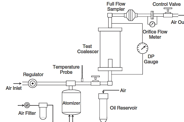
- Difficult aerosol challenge with drops ranging from 0,1 to 1 µm created in an atomizer – representative of condensation aerosols.
- Test operated under pressurized conditions – not vacuum.
- Coalescer evaluated after it is saturated with liquids – representative of field operation.
- Outlet contaminant collected by a full flow sampler that collects any aerosols or liquids flowing along the walls of the pipe.
Liquid/Gas Coalescer Applications
The separation of liquid aerosol contamination with high-performance liquid/gas coalescer cartridge systems has found widespread acceptance in refinery and How and For What Liquefied Petroleum Gas Reliquefaction Plants Workgas plants in recent years for a number of applications, including protection of compressors, turbo equipment, low NOx burner nozzles, amine and glycol contactors, molecular sieve beds, and well head hydrate inhibition. This has largely been the result of traditional separation approaches, including:
- knockout vessels,
- centrifugal separators,
- mesh pads,
- or vane separators,
not meeting the end user’s requirements for aerosol reduction. A brief description of some of the main applications is given here.
Compressor Protection
Contaminants in the inlet gas can have a severe effect on compressor reliability. At least 20 % of all reciprocating compressor failures can be attributed to inlet gas contaminants. Even when the compressors are not having catastrophic failure, a costly maintenance schedule may be followed where the compressor is shut down every 6 months or less for inspection and minor repairs. A preventative system using a high-performance liquid/gas coalescer system, however, has been found to provide protection of the compressor for a 2-year period.
Gas contaminants are made up of solid particulates and liquid aerosols, often including a high percentage in the submicrometer size range. Solids are usually corrosion products (iron oxides or iron sulfides), salts, or silt. Liquids can be:
- hydrocarbons (refinery products, lube oil, condensate);
- aqueous (water, alcohol, dissolved salts, caustic, acid);
- or a combination of both.
Contaminants affect reciprocating and centrifugal compressors in different ways.
Reciprocating compressors are affected by aerosol contaminant primarily in the piston cylinder intake/exhaust. A buildup of contaminants on the valves can lead to sticking valves or valves with partial bypass resulting in a reduced compression ratio and increased power consumption. The buildup of contaminants inside the cylinder can also damage the piston rings, pistons, and the cylinder wall.
Centrifugal compressors impart a dynamic head to the inlet gas by use of high-speed impellers that are confined in a casing containing stationary diffusers. While centrifugal compressors are less sensitive to inlet gas contaminants, they are still affected adversely. For centrifugal compressors, the primary contaminant-related problem is the buildup of foulants on the rotating blades (also known as salting). This can lead to a partial blockage in the flow path causing increased power consumption and can create an imbalance in the blades leading to serious mechanical failures due to resultant vibrations if left unchecked.
Amine/Glycol Contactor Protection
Gas-treating processes that use liquid-gas contactors can be prone to foaming when contaminants build up in the solvent systems. The most common gas-treating solvent systems are alkanol amines used to remove H2S or CO2 and triethylene glycol used to remove water vapor. Activated carbon and antifoam chemical additive are often used to alleviate foaming issues. These approaches are not effective for significant contaminant ingression, as the activated carbon becomes saturated past its capacity at a rapid rate. The use of antifoam treats a symptom rather than addressing the root cause by removing the contaminant.
It will be interesting: Characteristics of Natural Liquefied Gases
Upsets in contaminant levels can often trigger foaming, as it is difficult to gauge the respective antifoam level required. High levels of antifoam additive can also have the opposite effect and lead to foam promotion in some instances. A total fluid management approach of using high-efficiency liquid/gas coalescers on the incoming gas and 10-µm absolute filters on an amine loop was found to be an effective approach to minimizing foaming and amine losses.
Well Head Hydrate Inhibition
Hydrates, solid water/methane complexes, can form in natural gas under high pressures even at ambient temperatures. Hydrates can wreck havoc on gas processing and Raw Gas Transmission: Multiphase Flow, Hydrates, and Corrosion Challengestransmission systems by plugging off pipelines and process equipment. Methanol and/or glycol injection is often used to inhibit hydrate formation. Removing water aerosols right at the well head is an even more effective way to prevent issues with hydrates forming in the downstream pipeline and will reduce chemical injection costs for methanol and glycol.
Molecular Sieve Protection
Molecular sieves (zeolites) are used to dehydrate gas to achieve dew points well below saturation and are effective at removing water vapor. When free water in the form of aerosols is present, the molecular sieves can reach maximum water capacity rapidly, leading to frequent regeneration.
Regeneration is accomplished thermally and will have an associated cost for this heating value. Hydrocarbon and solid aerosols can lead to fouling of the molecular sieve bed, thereby reducing the number of active sites to bind to water vapor. The use of high efficiency liquid/gas coalescers is an effective and economic means to protect molecular sieve beds.
Low and Ultra Low NOx Burner Protection
Burners are used extensively in the refining and petrochemical industries. Applications include furnaces used for crude oil heating, cracking, reforming, and coking, as well as boilers, gas turbines driers, and incinerators. To meet environmental regulations, advanced burner technology including low and ultralow NOx burner tips is being applied increasingly. These advanced burner designs are more intricate in design and have finer orifices that are more prone to fouling than older designs.
Contamination in the Use of Cargo as Fuel on Gas Tankersfuel gas can lead to process problems with the furnace operation. The nozzles can become plugged, leading to poor furnace performance and, in extreme cases, damage the convective sections of the furnace. At some plants, furnace maintenance has become a costly task, requiring burner tip replacement or cleaning every few days. Fuel gas can contain contaminants from various sources. Corrosion products can form in the process piping and lead to fouling by inorganic materials. Liquid hydrocarbons can result in coking at the burner tip, leading to fouling by organic materials. Some of the contaminants found in fuel gas include:
- iron sulfides,
- iron oxides,
- amine,
- glycol,
- water,
- and hydrocarbon liquids.
High-efficiency liquid-gas coalescers have been applied successfully to protect low and ultralow NOx burners. They can be installed either at the point of use directly upstream of a bank of furnaces or at a central location conditioning the feed to multiple banks of burners. The piping should be cleaned thoroughly prior to installing the coalescers and any piping downstream of the coalescers should be either heat traced or insulated to prevent temperature drops that could cause liquids to condense.
High-Efficiency Liquid-Liquid Coalescers
Liquid-liquid separations may require the use of special equipment when the drop sizes are small, typically in the range of 1 to 50 µm in size. These fluid systems are classified as stable emulsions, and often conventional bulk separators with mist pads or plate-type internals will not be effective.
High-efficiency liquid-liquid coalescers have been developed to break these emulsions and provide improved separation.
Emulsions
Emulsions consist of the three components:
- oil (representing hydrocarbon or organic liquids);
- water (including any aqueous mixtures);
- and surfactants.
Depending on the ratio of these components, oil-in-water emulsions or water-in-oil emulsions can exist. The structure of the oil-in-water or water-in-oil emulsions is well defined with spherical droplets of the dispersed phase surrounded by a bulk continuous phase and surfactant sheathing the droplets. Surfactants contain both hydrophilic (water loving) and hydrophobic (water fearing) portions in the same molecule.
Source: AI generated image
This unique structure allows them to associate at water-oil interfaces and helps them stabilize the droplet shape. A spherical drop shape is formed to minimize the surface area between the oil and the water, which also minimizes the free energy required to make this surface. In order to make an emulsion the system must be subjected to shear or mixing to allow the three components to break up into the droplet structure.
Emulsions are inherently unstable and will spontaneously separate out into two bulk phases. This process requires that the small droplets merge together or coalesce repeatedly until they form increasing drop sizes that eventually merge with a bulk phase until all of the drops are gone. Depending on the nature of the emulsion, the separation can occur in a matter of seconds or months. Many of the same factors that affect emulsion stability also influence coalescer performance.
Surfactants
Surfactants can be broadly classified into three groups:
- cationic,
- anionic,
- and nonionic.
All surfactants consist of polar or hydrophilic groups joined to nonpolar or hydrophobic hydrocarbon chains. Cationic surfactants contain polar head groups that have a positive charge whereas anionic surfactants have polar groups that have negative charges. Nonionic surfactants have polar groups that are neutral and are typically made up of ethylene oxide groups.
Surfactants can have a wide array of configurations, including a polar head and nonpolar tail structure, branched tails, and random placement of polar groups within a nonpolar hydrocarbon chain. The ability of surfactants to aid in the emulsification process will depend on the ratio of the polar to nonpolar groups, the charge density and size of the polar group, and the volume occupied by the nonpolar groups (branching and length). Surfactants can also be influenced by other species such as cosurfactants (alcohols) or aqueous contaminants (salts).
The sources of surfactants found in industrial processes include intentional additives, surfactants found in nature, and surfactants created inadvertently through reaction processes. Some examples of surfactants classified this way are given.
Additives:
- corrosion inhibitors,
- deemulsifiers,
- scale inhibitors,
- flocculents.
Natural:
- petroleum naphtha sulfonates,
- naphthenic acids,
- and mercaptides in crude oil.
Reaction products:
- oxidation/caustic treatment of hydrocarbons in refineries leading to formation of cresylic acids and phenol homologs.
Coalescer Principles and Materials of Construction
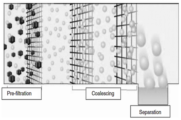
Coalescers are typically manufactured as either pads or cartridge filters that have been designed especially to take small droplets in an emulsion and grow them into large drops that are separated more easily. This process is accelerated over natural coalescing by the fibers present in coalescer media that force the contact of small droplets, thereby promoting the coalescing process. The pore gradient of coalescer medium is constructed so that the inlet medium has fine pore sizes that increase in size with the flow direction (see Figure 5).
Coalescers have been primarily constructed with glass fiber media until recently when polymer and fluoropolymer materials were adopted. Glass fiber works adequately for emulsions with interfacial tensions >20 dyne/cm. It is known to disarm and lose efficiency in the presence of surfactants. These coalescers are widely used to dewater jet fuel for the aviation industry.
High-efficiency liquid-liquid coalescers are the newest generation of coalescers, incorporating the latest in coalescer technology. They are constructed from polymer and fluoropolymer materials that have been optimized to separate the most difficult emulsions with interfacial tensions as low as 0,5 dyne/cm. This coalescer can be used with a broad range of applications. It can process aggressive chemicals and handle demanding operating conditions while providing the highest level of performance.
Coalescer Mechanism of Operation
The liquid-liquid coalescing system operates in three stages:
- separation of solids/preconditioning;
- coalescence;
- and separation of coalesced drops.
Separation of Solids/Preconditioning of fluid
Solids can increase the stability of an emulsion and removing solids can make coalescing easier. Generally, this step can be achieved by a separate cartridge filter system or by a regenerable backwash filter system for high levels of solids. In addition, the filtration stage protects the coalescer and increases service life. This step also initiates the coalescence of the hydrocarbon droplets, thereby enhancing the separation capabilities of the system.
Coalescence
The next step in the process is primary coalescence. In this stage, pore dimensions begin with a very fine structure and then become more open to allow for void space for the coalescing droplets. In the primary coalescence zone, the inlet dispersion containing fine droplets in the size range of 0,2 to 50 µm is transformed into a suspension of enlarged droplets in the size range of 500 to 5 000 µm.
The coalescence mechanism can be described by the following steps.
- Droplet adsorption to fiber.
- Translation of droplets to fiber intersections by bulk flow.
- Coalescence of two droplets to form one larger droplet.
- Repeated coalescence of small droplets into larger droplets at fiber intersections.
- Release of droplets from fiber intersections due to increased drag on adsorbed droplets caused by bulk flow.
- Repeat of steps 1-5 with progressively larger droplet sizes and more open media porosity.
Based on this mechanism, we can predict that a number of factors will influence the coalescence performance. The specific surface properties of the coalescer fibers are critical in influencing the adsorption of droplets as well as the ultimate release after coalescing. There is a balancing act between increasing the attraction or adsorption characteristics of the fibers against the release mechanism, which strong adsorption would inhibit.
The necessary condition that droplet – fiber adsorption occurs for coalescing has been supported by a number of sources.
Separation of Coalesced Droplets
Once the droplets have been coalesced they are now as large as possible for the given flow conditions. The Phase Separation: An Essential Process in Hydrocarbon Productionseparation stage can be achieved in one of two ways.
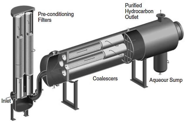
Horizontal Configuration. The coalescer housing contains a settling zone that relies on the difference in densities between the coalesced droplets and the bulk fluid (see Figure 6). This configuration can be used for both hydrocarbon from water and water from hydrocarbon separation, but the location of the collection sump and outlet nozzle will need to be reversed. For the case of removal of hydrocarbon from water, a collection sump is located at the top of the housing and the purified water leaves at the bottom outlet nozzle. The sump can be drained manually on a periodic basis or equipped with an automatic level control and drain system. Estimation of the coalesced drop size and required settling zone are best determined through pilot scale tests at field conditions.
Vertical Configuration. Once the droplets have been coalesced they are now as large as possible for the given flow conditions, in the range of 0,5 to 2 mm in diameter. The separation stage is achieved using hydrophobic separator cartridges that provide an effective barrier to aqueous coalesced drops, but allow hydrocarbon to pass through them. The separator cartridges can be stacked below the coalescers for the most efficient utilization of the separator medium. This configuration only applies to the separation of water or aqueous contaminants from hydrocarbons (see Figure 7).
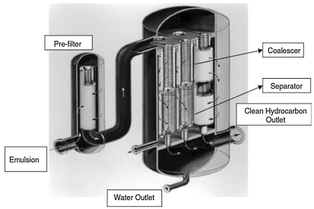
After leaving the coalescing stage, the large aqueous coalesced drops and hydrocarbon then flow axially in a downward direction and the flow direction is from the outside of the separator to the inside. The large coalesced drops are repelled by the separators and are collected in the bottom sump. The purified hydrocarbon passes through the separators and exits at the bottom of the housing. The aqueous phase in the collection sump can be drained manually on a periodic basis or equipped with an automatic level control and drain system.
Liquid/Liquid Coalescer Performance
Properly designed and sized high-efficiency coalescer systems can process inlet discontinuous phase concentrations up to 10 % and reduce them to ppm levels in the outlet for interfacial tensions as low as 0,5 dyne/cm. For water from hydrocarbon separations, coalescer outlets below 15 ppmv per the AquaGlo (registered trademark of Gammon Corp.) method (ASTM D3240) can be achieved, and for hydrocarbons from water, concentrations below 20 ppmw per the oil and grease method have been demonstrated.
The use of polymers and fluoropolymers in the coalescer materials of construction allows for the expanded use of coalescers over earlier conventional types so that they can withstand an array of aggressive chemical applications over a wide range of temperatures from -40 °F up to 300 °F.
Limitations of Using Coalescers
While liquid-liquid coalescers have many benefits in breaking tough emulsions, there are some limitations to consider. Solids can become problematic at higher concentrations and lead to excessive change out of disposable prefilters. Generally, the solids range that liquid-liquid coalescers can operate economically with disposable filters is <10 ppm.
Above this level of solids, further pretreatment will be required, such as backwash cartridge filters, mixed media packed beds, or hydrocyclones for solids removal.
Read also: Liquefied Natural Gas Tank Protection
Operational limits of the coalescer for the removal of free liquids must also be understood. If the clarified stream leaving the coalescer is then cooled, condensation of a previously dissolved contaminant can occur, leading to a hazy fluid at the lower temperature. The coalescer will not be able to remove contaminants that are dissolved in solution and, therefore, the location to place the coalescer and any subsequent change in process conditions after the coalescer must be considered carefully.
Coalescers typically will have a service life of 1 to 2 years when protected adequately by prefiltration. Despite the long life, the coalescers will eventually require disposal and replacement; however, this will be minimal given the low frequency of replacement.
For liquid–liquid coalescers constructed from glass fiber medium, the problem of surfactant disarming must also be considered and for low IFT emulsion systems (<20 dyne/cm) they will not operate efficiently for separation. For these conditions, nondisarming fluoropolymer or polymer coalescers should be considered. These types of materials also have wider compatibility for chemical streams and a wider temperature range.
Applications
High-efficiency liquid-liquid coalescers are finding increasing applications in industry where problematic emulsions exist. They are used to protect equipment, to recover valuable streams, and to meet environmental discharge limits. Some examples are given.
Pipeline Condensate
In gas production, associated light-end hydrocarbon condensates and water are produced along with the gas. In many instances, chemical additives such as methanol and glycol are used to prevent hydrate formation. These chemicals can increase greatly the tendency for the water-hydrocarbon condensate to form stable emulsions. High-efficiency liquid-liquid coalescers have been applied to separate these difficult emulsions to purify both water and hydrocarbon phases.
Produced Water
Discharge limits on produced water are becoming more stringent with current levels in many areas at 29 ppm oil and grease. To treat produced water to achieve this target often requires multiple separation options, including mixed sand beds, dissolved air flotation, and hydrocyclones.
Despite these efforts, emulsified oil can still penetrate through to the effluent, and the use of high efficiency liquid-liquid coalescers offers a reliable way to meet environmental limits.
Petrochemical Final Products
In refinery operations, steam stripping is often used to remove volatile components (hydrogen sulfide and light hydrocarbon fractions) from petroleum products, including gasoline, diesel, and kerosene. This can lead to water condensation and off specification hazy final products.
Caustic Treating
In the production of gasoline, organic sulfur compounds such as mercaptans often need to be removed. One of the more well-known processes for the removal of mercaptans is known as the Merox (registered trademark of UOP) process, which is licensed by UOP. In the reactor, mercaptans are extracted into the caustic and are then converted to disulfide oils by oxidation and catalytic action. Phenols are also extracted into the caustic phase. The reactor effluent flows to a three-phase separator where air, disulfides, and regenerated caustic are separated. The regenerated caustic is then recycled to the reactor.
It will be interesting: Liquefied natural gas (LNG) – The Ideal Gas
The reactor effluent typically contains a quantity of carried over caustic that results in hazy gasoline product, high costs of caustic make-up, and corrosion of downstream piping. The hazy gasoline is problematic and has to be blended off or reprocessed, as it would cause the product to be off-specification in terms of sodium. Installing a high-efficiency liquid-liquid coalescer system was found to be an effective solution to recover the caustic carryover.
Recover Liquid Catalysts
Liquid or homogeneous catalysts are used in a number of processes where the catalyst and the reactants are insoluble and form emulsions. Recovery of the catalyst is important to reduce the need for make up catalyst and to protect downstream equipment from fouling by the catalyst.