Explore our comprehensive guide on handling non-standard and emergency situations on LNG carriers. Learn about multiple cargo pump failures, gas freeing, inerting, aeration, part load and discharge, loss of gas handling capability, power loss, primary containment issues, ballast tank leakage, nitrogen supply failure, jettisoning cargo, overfilling, pipeline containment loss, and more. Ensure your LNG operations are prepared for any emergency with our expert insights and best practices.
- Situations
- Multiple Cargo Pump Failure in One Tank
- Gas Freeing a Single Tank
- Warm-up
- Inerting
- Aeration
- Part Load and Discharge
- Non-Availability of Key Equipment
- Loss of Gas Handling Capability
- Prolonged Loss of Power to Cargo and Ancillary Systems
- Loss of Primary Containment
- Loss of primary barrier on membrane type ship
- Loss of primary barrier on Moss type ship
- Ballast Tank Leakage into Containment Space
- Ballast tank leakage into containment space – membrane ship
- Ballast tank leakage into containment space – Moss type ship
- Nitrogen Supply Failure
- Jettison of Cargo
- Overfilling of a Cargo Tank
- Loss of Cargo Pipeline Containment
- Liquid cargo line leakage
- Vapour line leakage
- Failure of Integrated Automation System
- Uncontrolled Release of Cargo
Reference: SIGTTO “LNG Shipping Suggested Competency Standards”, Sections:
1 Have an awareness of the types of non-standard operations:
- pressurised discharge;
- use of emergency discharge pump;
- single tank gas free;
- partial loading;
- key equipment not available;
- loss of gas burning capacity;
- prolonged loss of power to cargo and ancillary systems.
2 Have an awareness of the types of emergency operations:
- loss of primary containment;
- ballast tank leakage into containment space;
- nitrogen supply failure;
- jettisoning cargo;
- overfilling a cargo tank;
- failure of integrated automation system;
- uncontrolled release;
- loss of cargo pipeline containment.
| Non-standard conditions include, but are not limited to, the following situations | |
|---|---|
| Pressurised discharge | Use of emergency discharge pump |
| Single tank gas freeing | Ship to ship transfer |
| Partial loading/discharge | Non-availability of key equipment |
| Loss of gas handling capability | Prolonged loss of power to cargo and ancillary systems |
Situations
Pressurised discharge
Moss type ship. If both cargo pumps in any single Moss tank were to fail, the balance of cargo remaining in that tank can be transferred to another tank by the action of vapour pressurisation above the liquid in the affected tank.
The transfer rate in this case would be controlled by regulating the pressure within the tank.
The transfer of cargo from the tank would normally take place at sea after the Main Procedures and Best Practices of Liquefied Gas Discharge from LNG Carrierscompletion of discharge.
Use of the emergency cargo pump
Membrane type ship. The emergency cargo pump is used in the event of both cargo pumps failing in any single cargo tank. The pump is lowered within the emergency pump column for that tank. Cables and a connection to the local junction box are used to power the pump. The pump, when lowered and positioned, opens a foot valve in the column that allows the LNG to be pumped out.
If an emergency pump is provided, it must be designed so that it can be left in place until a permanent cargo pump repair can be carried out.
Single tank gas freeing
There may be several reasons for single tank gas freeing. For example, it may be necessary for in-tank repairs to be carried out with the ship in service. The primary difficulty of single tank gas freeing is ensuring the total isolation from other tanks.
It is extremely unlikely that tank barrier repairs would be carried out with only one tank warmed up.
Partial loading/discharge
Regardless of the type of ship and its tolerance to partially loaded conditions, reduced stability due to increased free surface is always an issue. It is the responsibility of the Chief Officer to ensure that the ship’s stability and associated stresses are, at all times, within the operating limits for the ship, under any partially loaded condition.
Unlike the robust Moss type spheres, membrane ships have an added complication due to the increased risk of primary containment damage from Dynamic Strength Analysis for Membrane Type LNG Containment System Due to Sloshing Impact Load“sloshing” induced forces.
Non-availability of key equipment. There is a high level of redundancy built in to essential equipment on an LNGC. Key equipment redundancy, and a rigorous regime of testing, are the main means of defence against “unavailability”.
Loss of gas handling capability. As there is a requirement in the IGC Code for a primary and backup system, total loss of gas handling capability is highly unlikely. However, in the event of such a failure, the response must focus on maintaining cargo conditioning within acceptable parameters, relying on the venting arrangements as a primary means of doing so.
Prolonged loss of power to cargo and ancillary systems
The design of a new LNGC avoids a “prolonged” power disruption to the cargo system or any of the ship’s consumers through redundancy. The main switchboards can be split and sections isolated and there is a sophisticated power management system (PMS). This means that while a prolonged power disruption can never be entirely ruled out, any disruption is likely to be only temporary.
Equally important is the supply to the IAS and the control loss to all associated systems, including the cargo system. The IAS is supplied via two uninterruptible power supply (UPS) units, one fed from the emergency switchboard and the other from the main switchboard. The change over between units is “make before break” and each is required to have the capacity to supply the IAS for a minimum of 30 minutes in the event that mains or emergency power supply is lost.
If a prolonged power disruption occurs then cargo management will revert to local manual operation of the vapour vent valves.
Emergency conditions/operations. The emergency conditions and operations include, but are not limited to, the following situations:
- loss of primary barrier;
- ballast tank leakage into containment space;
- nitrogen supply failure;
- jettisoning cargo;
- overfilling a cargo tank;
- failure of IAS;
- uncontrolled release;
- loss of cargo pipeline containment.
Loss of primary barrier
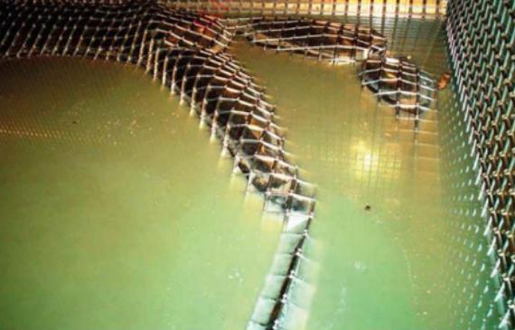
Membrane ship. The insulation system is designed to reduce the boil-off losses from the cargo to an acceptable level and to protect the inner hull steel from the effects of excessively low temperature. If the insulation efficiency should deteriorate for any reason there will be an increase in boil-off from the affected tank and the inner hull steel temperature may form a cold spot. If resolurtion is beyond the capability of the gas handling equipment, excess boil-off gas may be vented to the atmosphere via No. 1 vent mast. The inner hull steel temperature must, however, be maintained within acceptable limits to prevent possible brittle fracture.
Thermocouples are distributed over the surface of the inner hull but, unless a cold spot occurs immediately adjacent to a sensor, these can only serve as a general indication of steel temperature. Currently, the only reliable way of detecting cold spots is by frequent visual inspections of the ballast spaces on the loaded voyage.
The grade of steel required by the inner hull of a ship is governed by the minimum temperature this steel will reach at ambient temperature, assuming that the primary barrier has failed and the LNG is in contact with the secondary membrane.
With sea and air temperatures of 0 °C and failure of the primary barrier, the minimum temperature of the inner hull steel will be about minus 26 °C (-26 °C). For these conditions, Classification Societies require a specific steel grade distribution, where the tank top and top longitudinal chamfer are in grade “E” steel, and the remaining longitudinal steelwork grade “DH”. Both grades have a minimum operating temperature of minus 30 °C (-30 °C). The transverse watertight bulkheads between cargo tanks are of grade “A”, with a glycol water heating system.
In this condition, cargo containment becomes secondary barrier dependent.
Moss type ship. With the robust “leak before fail” concept for spherical tanks, any minor leakage would be classed as a serious failure of the tank structure. In such a situation any liquid flow from the upper hemisphere will be collected in the drain channel formed by the upper ring stiffener of the skirt. There are four drain pipes, port, starboard, forward and aft of the tank, which lead any cargo leakage to the catch basin. Any liquid flow in the lower hemisphere will be led to the drip pan by a drain pipe at the tank’s south pole.
In this condition any cargo leakage would be contained by the drip pan. On a Moss type ship, if there has been any containment system leakage the hold spaces will need to be inerted.
Ballast tank leakage into the containment space, hold or secondary (insulation) space
Membrane type ship. Ballast water leakage from the wing tanks into the insulation spaces (secondary) can occur through fractures in the inner hull plating. If the leakage remains undetected and water accumulates in these spaces, ice will be formed. Ice accumulation can cause deformation and possible rupture, of the insulation. The resultant cold conduction paths forming in the insulation will cause cold spots to form on the inner hull.
The pressure differential caused by a head of water building up in the insulation space may, in extreme cases, be sufficient to deform or even collapse the membrane into the cargo tank.
To reduce the risk of damage from leakage, each cargo insulation space (secondary) is provided with water detection units and a bilge piping system connected to two pneumatic pumps. Detection of water will trigger an alarm and the location will be shown on the IAS.
Moss type ship. Inner hull issues are the same as for membrane ships, but leakage water is collected in the sump situated at the after end of the hold space, under the cargo tank. The water leakage collects in this sump, where monitoring equipment for temperature and liquid presence is installed. This triggers a bilge alarm that displays in the CCR via the IAS. The gas detectors are situated in a different part of the hold space.
N2 supply failure
An N2 plant has considerable redundancy, making complete failure highly unlikely. A typical system includes two Nitrogen Generator System on Liquefied Natural Gas Carriersnitrogen generators installed in the engine room, producing gaseous N2, which is used for the pressurisation of the insulation/annular spaces, as seal gas for the cargo equipment, compressor house bulkhead drive shaft sealing, fire extinguishing medium for the vent masts and for purging the fuel gas system and various parts of the cargo piping.
The operating principle is based on hollow fibre membranes through which compressed air flows and is separated into O2 and N2. The O2 is vented to the atmosphere (note that venting safety requirements apply to enriched oxygen) and the N2 is stored in a buffer tank, to provide capacity for short period supply disruption.
If total failure or disruption for a prolonged period occurred, N2 dependent consumers would trip or be manually stopped until supply was re-established. Specific disruption details are covered in “Jettison of Cargo” below.
Jetisson of cargo
Warning – the jettisoning of cargo is an emergency operation. It should only be carried out to avoid serious damage to the cargo tank and/or inner hull steel structure.
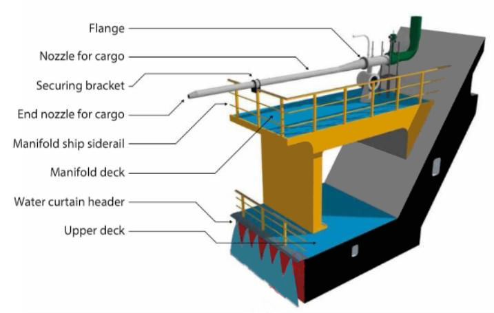
A containment or insulation failure in one or more cargo tanks may necessitate the jettisoning of cargo from that particular cargo tank to the sea. This is carried out using a single main cargo pump, discharging LNG through a jettison nozzle fitted at the ship’s manifold.
Overfilling a cargo tank (see in “Loss of Cargo Pipeline Containment” below)
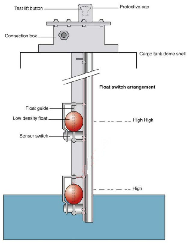
High level and overfill alarm system (Moss type LNGC). The ship’s cargo tank and high level alarm systems are fitted to comply with the IMO, Classification Society, USCG, etc., requirements. To comply with these requirements, the high level and overfill alarms are completely independent.
The level switches are of a float type and can be tested independently from the top of the tank. Typical settings on a Moss type ship would be 99,5 % for high level with automatic loading valve closure and 99,7 % for overfill and initiation of the ESD1 trip system.
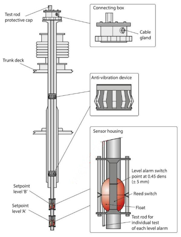
High level and overfill alarm system (new membrane type LNGC). The level switches are of the float type and can be tested independently from the top of the tank. There are two individual systems in each tank, one for high level 95 % that initiates an alarm warning and one for extreme high level 99 % that initiates an ESD1 trip.
When the tank level comes up to 98,5 %, the TPS (tank protection system) automatically closes the filling valve of the related tank. If the cargo tank level is higher than 98,5 %, the IAS outputs a signal by changing the normally energised contact to be de-energised to initiate the process of loading valve closure by the TPS.
Failure of IAS
The IAS is designed with redundancy and normal operation of the ship without it is not possible. Some equipment normally controlled by these systems can be manually operated in emergency situations, i. e. provision for firing the boilers manually and locally is a facility common to all ships. This does not mean that the cargo or machinery plant can be operated safely for a prolonged period without the IAS in its entirety. Interlocks, a limited number of personnel on board and the large distances between items of critical equipment make the IAS a necessity and efforts must always be directed at re-establishing IAS control.
Uncontrolled vapour release typical response
This should involve the following:
- raise the alarm. Response teams muster;
- activate the IMO spray system and provide firehose protection for the affected steelwork;
- PA announcement alerting all personnel. Smoking and naked flame restrictions in force;
- establish control and brief response teams. Fire response measures must be discussed;
- isolate source of the uncontrolled release, as far as possible by remote operation of associated valves. Ship’s drawings and overlays may be required to fully establish all lines/systems that require isolation;
- if at sea, any associated cargo operations must be terminated, i. e. spraying, etc.;
- BOG handling terminated where appropriate;
- ESD1 trip activated if appropriate;
- the ship’s course adjusted to provide the most favourable conditions with regard to the methane cloud;
- accommodation secured;
- E/R informed and hot work suspended;
- accommodation A/C switched to recirculation mode;
- cargo condition adjusted to minimise the effect of the uncontrolled release, i. e. cargo tank pressure reduced, etc.;
- operating company/terminal kept appraised of the situation.
Loss of cargo pipeline containment
| Liquid Line Leakage | |
|---|---|
| Discover | LNG leakage of any size must not be ignored, no matter how small as pipelines are designed to be tight and any leakage is unacceptable |
| Report | Prompt reporting of any liquid leakage to the CCR is vitally important |
| Response | Protection of any steelwork and isolating the leak are the main objectives |
| Minor liquid leaks | Initial responses regarding reporting, steelwork protecting and isolation remain the same |
Vapour line leakage. Procedures are as for a liquid line leakage, but with the following additional considerations:
- all entrances must be closed and the air conditioning system changed over to the full recirculation mode. Smoking restrictions must be rigorously enforced anywhere in the accommodation;
- response teams may consider vapour cloud displacement by using firehoses set at full spray;
- as an approximate guide, the entire visible vapour plume should be considered as flammable.
Multiple Cargo Pump Failure in One Tank
Reference: SIGTTO “LNG Shipping Suggested Competency Standards”, Sections:
1 Know and understand the principles and procedures for multiple cargo pump failure:
- what type of vessels require an emergency cargo pump arrangement and the reasons;
- changes in operational requirements that may be required for the main cargo tank containment systems.
2 Know and understand procedures for the use of emergency cargo pump:
- fitting of cargo pump into cargo tank;
- precautions to be implemented throughout operations;
- criteria to be monitored during fitting and operation of pump.
3 Know and understand the procedures for pressurised discharge:
Generally, two cargo pumps are fitted in each cargo tank. In the event of failure of both cargo pumps in one tank, an LNGC still maintains the capability to safely discharge the cargo from the affected tank. The procedures vary depending on ship type.
Membrane type ships. An emergency cargo pump is available on membrane type ships.
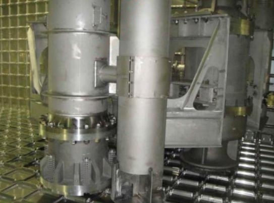
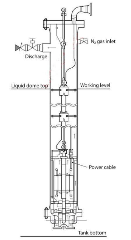
Each membrane ship carries an emergency cargo pump and rigging equipment that can be used in the event of failure of either one or both cargo pumps in a particular tank. The cargo tanks are equipped with an emergency pump column. This pump column has a foot valve that is held in the closed position by highly loaded springs. The emergency pump is lowered down the column after purging with N2 and the weight of the pump overcomes the compression of the springs to open the foot valve.
A small flow of N2 should be maintained into the pump column while the pump is being installed. Electrical cables and a connection to the local junction box are used to power the pump. LNG can then be pumped out.
It is important to reduce cargo tank pressure to near atmospheric pressure and this must be maintained throughout the installation/fitting. Full instructions will be found in the ship specific cargo operating manual for fitting and operation. While all equipment is available on board, it may on occasion be necessary to seek shore assistance for installation.
Note that if only a small quantity remains inside the cargo tank, the spray pump can be utilised, which is quicker and safer than rigging the emergency cargo pump. Beside each pump column is a local junction box for the cargo pump connection and a local start switch.
The pump is supplied with a set of:
- lifting strops;
- three phase cargo pump power cables;
- head plate with cable terminal box, power cables and mounting frame for terminal box;
- link plates fitted with roller guides to match the number of lifting points.
The pump is suspended over the column into which it is being lowered by a crane/dedicated davit. A support flange to take the weight of the pump is used to connect each strop. The pump discharges into the column and to the liquid line via a discharge connection and valve at the top of the column.
When not in use, the emergency pump is installed in a special airtight, moisture controlled enclosure. This has connections to introduce N2, which ensures that the pump can be kept in a “dry” atmosphere prior to use. Safety notes should be posted on the emergency pump enclosure, advising of the potential internal pressure and low O2 content.
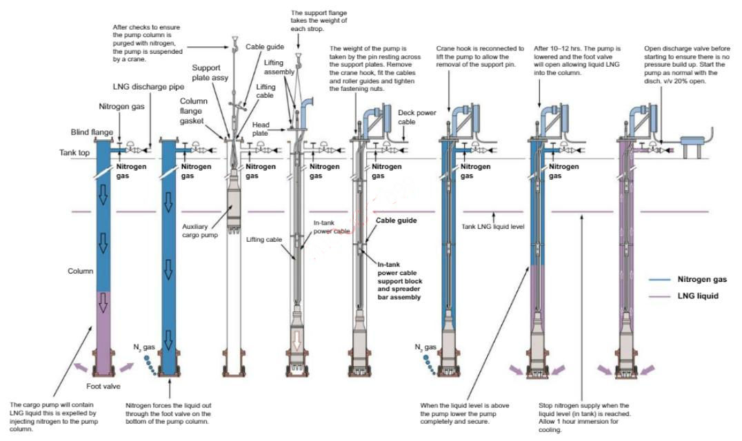
When all equipment, pump, cables, electrical connection box and accessories are in position near the tank in which the pump is to be installed, prepare the crane/dedicated davit to lift the pump and start the pump installation. A typical procedure for cargo pump installation is:
- the column into which the emergency pump is being lowered must be purged. This is achieved by injecting N2 into the column. In the case of a full cargo tank, a pressure of between 2 and 3 bar is required. The N2 forces the liquid out through the foot valve located at the bottom of the column;
- on completion of the expulsion of the liquid, a check must be made at the purge cock to ensure complete inerting has taken place. The tank pressure must be reduced to just above atmospheric before removing the column top blank flange. Install a new column flange gasket, then begin to instal I the pump using the crane/dedicated davit;
- install the power cables on the pump. Ensure that the power cables are carefully laid out on deck and protected to avoid any damage. The power cable markings should coincide with the markings on the pump to ensure correct phase rotation;
- attach a strop to the pump lifting link plate and a link plate to the top eye of the strop. Attach the crane/davit hook and lift the pump. Suspend it above the column and lower the pump into the column;
- when the pump is lowered into the column, fit the support flange with U-slot to the column and pass the support pin through the centre of the link plate. Lower the link plate so that the weight of the pump is taken by the pin resting across the support plates. Remove the crane/davit hook. Fit the cables and roller guides to the link plate and tighten the nuts;
- fit the next strop to the top of the plate and fit the next link plate with cables and roller guides to the eye of that strop. Attach the crane/davit hook and lift the pump a few centimetres to remove the support pin. Lower the pump 2,5 m into the column and repeat the last stage until all strops are attached;
- fit the head plate lifting rod eye to the link plate and fit the crane/davit hook to the top eye. Lift the pump a few cm to remove the support pin. Take care not to lower the pump onto the foot valve;
- lower the head plate onto the column and install the head plate with the lifting assembly in the closed position, being very careful with the gasket;
- install the electrical assembly and support brackets. Install the deck power cable assembly, making sure that the appropriate markings are matched at all connecting points.
Operating procedure – pump cooldown and operation:
- start the cooldown for the pump. The pump should be left suspended in the empty column for 10 to 12 hours;
- after 10 to 12 hours introduce N2 pressure in the column to open the suction foot valve with the lifting assembly in the closed position;
- decrease the N2 pressure slowly to let the liquid rise in the column at a speed of approximately 75 to 125 mm/minute, until it covers the pump completely (approximately 2 m). When the liquid level in pump column reaches approximately 2 m, boil-off gas in the column will be rapidly reduced because of the completion of cooldown of the pump;
- when the liquid level is above the pump, maintain the N2 gas pressure and lower the pump completely by adjusting the lifting assembly to the open position. Tighten the gland onto the lifting rod through the head plate;
- stop the N2 supply when the liquid is at the same level in the tank and the column and bleed the N2 from the top of the column. The pump will have to stay immersed in the liquid for one hour before being started;
- before starting the pump, open the discharge valve to ensure that there is no pressure built up at the top of the column when starting the pump. If necessary, excess pressure can be bled off via the purge cock;
- when ready to start the pump, open the discharge valve 20 % and start the pump normally;
- check the operation carefully to ensure that there is no leakage at the top of the column or discharge piping. Firehoses must be under pressure and ready in the vicinity before starting.
Adjust the opening of the discharge valve to have the required discharge flow and pressure within the pump capacity.
Moss type ship. If both cargo pumps in any single Moss tank were to fail, the balance of cargo remaining in that tank can be transferred to another tank by the action of vapour pressurisation above the liquid.
The transfer of cargo from the tank would normally take place at sea after the completion of discharge. Using this method, cargo is pressed up and displaced into the filling line by means of increased vapour pressure above the liquid.
The transfer rate In this case would be controlled by regulating the pressure within the tank.
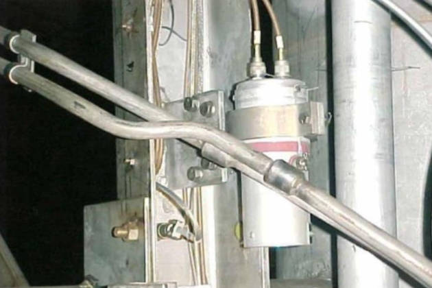
The increase of pressure is achieved by pumping LNG from another cargo tank using a spray pump to the vaporisers, with the resultant vapour introduced into the affected tank through a flexible connection at the tank dome inlet.
Relief valves on the cargo tank are normally set at a pressure of 250 mbar. This pressure setting will be increased using dedicated equipment to adjust the pilot valve set point to initially, approximately 1 bar and then up to 1,9 bar. Adjustments and subsequent re-adjustments of safety valves should only be carried out under supervision of a senior officer and recorded in the ship’s log book.
The exact valve line up should be as detailed in the cargo operating manual.
The following is an example of a procedure on a 137 000 m3 Moss type ship:
- the cargo tank high pressure alarm (alarms at ~220 mbar) should be inhibited;
- discharge the other 3 cargo tanks, leaving at least 1 500 m3 of liquid in one tank (to produce the vapour);
- complete cargo discharge and leave the port to open sea;
- connect a flexible hose on the affected tank to the adjacent pressure build-up line;
- prepare the spray lines to cool down the spray header (using the tank with the 1 500 m3 of liquid);
- start the spray pump, circulating back to the same tank via the spray nozzles.
- the vaporiser should be prepared for operation in the manual mode:
- temperature control valve at minus 60 °C (-60 °C);
- control valve at 60 mbar (or the prescribed value);
- open spray header valve to the LNG vaporiser;
- set vaporiser valves as necessary;
- open vaporiser discharge to pressure buildup main;
- start spray pump supplying the vaporiser;
- monitor the tank pressure in the affected tank carefully. This will rise rapidly for the first hour and then stabilise and fall off. As the tank liquid level reduces, the vapour pressure will have to be increased to maintain the cargo flow;
- ensure that tank pressure in the affected tank does not reach the setting of the safety valve.
- when the affected tank has been discharged, stop the spray pump to stop the creation of vapour (leave the steam on the Use of Vaporisers on Liquefied Natural Gas CarriersLNG vaporiser until all cargo has flashed off and the vaporiser has warmed up, then secure the unit);
- remove flexible, cryogenic hoses and line up the cargo system to normal operating conditions;
- return the pilot valve on the affected cargo tank to the original setting;
- restore all alarms to their normal settings.
It would be normal for the Low Duty Compressor(s) on the Liquefied Natural Gas CarriersLD compressors to continue supplying BOG to the boilers through the gas heater from all tanks except the affected one during the cargo transfer.
The ship can now return to complete the discharge operation prior to the single tank warm-up, inerting and aerating operations before replacing the defective cargo pumps.
Gas Freeing a Single Tank
Reference: SIGTTO “LNG Shipping Suggested Competency Standards”, Sections:
1 Know and understand the procedures:
- reasons for operation;
- method to be used to change tank atmosphere;
- pipeline “line-up” requirements with reference to maintaining:
- isolation between tank to be gas freed and remaining cargo system;
- ability to control vapour pressure in remaining cargo tanks throughout.
A detailed plan must be prepared for this operation. Prior to entry, a risk assessment and permits for enclosed space entry and specified work must be prepared.
It is essential to know the pipeline “line up” requirements for maintaining:
- isolation between the tank to be gas freed and the cargo system;
- controlling vapour pressure in the remaining cargo tanks throughout.
Single tank warm-up, inerting and aeration
It may be necessary for repairs to be carried out in a gas hazardous area with the ship in service. Tank barrier repairs would not be carried out with only one tank warmed up, inerted and aerated. Single tank warming and aeration can be carried out while the remaining tanks are maintained in the cold condition.
Preparation, Operations, and Considerations of Liquefied Gas Tanks AerationAeration should be continued throughout the repair period to prevent ingress of humid air to the cargo tank. Tank venting is carried out through the emergency vent header.
Operation. At the discharge port, the tank to be worked on is discharged to the lowest measurable level and, after completion of the custody transfer procedure, as much as possible is transferred to other tanks using the spray/stripping pump if required. Sufficient heel for the voyage, where required, together with an extra amount for gassing up or cooling down after completion of repairs, is retained in one of the other tanks.
Warm-up
Normal vapour management is continued during this operation. Normal BOG procedures are followed until this operation has stabilised, then the operation for Efficient Liquefied Natural Gas Tank Warming Procedureswarming up one tank using an HD compressor is carried out. Spool pieces are fitted according to any specific instructions laid down in the cargo operating manual.
Inerting
Normal gas burning, where appropriate, is continued during this operation using vapour from the in-service tanks. IG is supplied to the tank by the IG plant via the blind flange valve that connects the IG line with the liquid header. Venting the tank is achieved via a spool piece connecting the vapour outlet from the tank to the IG header. The isolation valve to the vapour header must remain closed.
Tank pressure and other values must be continually monitored. During inerting, the pressure in the tanks must be kept low to maximise the “piston effect” and to reduce mixing. Regularly test the discharge from the vapour dome for hydrocarbon content and verify that the O2 content of the IG remains below 3 %.
Where necessary, purge all of the unused sections of pipeline, machines, equipment and instrumentation lines with N2. Before shutting down the IG plant, ensure the liquid header is purged through to the No. 1 vent mast in preparation for aerating the tank.
When the hydrocarbon content at the tank outlet falls below 1,5 %, isolate and shut in the tank. On completion of tank and pipeline inerting, stop the IG supply and shut down the IG plant. Reset the valve system for aerating.
Aeration
Dry air is supplied to the tank by the IG plant via the blind flange valve and spool piece connecting the IG line with the vapour header. Venting the tank is carried out via the liquid filling valve, exhausting into the liquid header and on to No. 1 vent mast via the spool piece. The isolation valve to the vapour header must remain closed.
There must always be complete isolation between the aerated tank and the tanks remaining in a gassed up or inerted condition.
Ensure pressure in the aerated tank is higher than in tanks containing vapour to avoid leakage of gas. Aerate all unused sections of pipeline and instrumentation lines.
A plan and risk assessment must be prepared prior to these cargo operations. Prior to tank entry, an enclosed space entry permit must be prepared.
Aeration must continue throughout the repair work period.
Part Load and Discharge
Reference: SIGTTO “LNG Shipping Suggested Competency Standards”, Sections:
1 Have a knowledge and understanding of the procedures to be followed:
- effect of sloshing loads on membrane type tanks;
- tank level restrictions that may apply.
The current market has seen a need for:
- LNGCs able to operate in the partially loaded condition;
- offshore loading and offloading of LNGCs that can operate in unrestricted partially filled conditions.
Sloshing loads represent a substantial hazard for membrane type LNGCs and can, potentially, lead to cargo containment system damage or failure .
Moss type ship. The robust tank construction provides more tolerance of “sloshing” induced forces. However, the trellis can impose operational limits. The operator must be guided by the maker’s specification, but Moss spheres are generally robust and can handle a wide range of partially loaded tanks.
Membrane type ship. The have been incidents on membrane type LNGCs that have resulted in damage of the insulation boxes when in the high filling condition. Damage when in the low filling condition was also reported, but this was limited, occurring primarily when the No. 1 cargo tank was loaded to between 15 and 20 % of the tank height to provide LNG as coolant for other empty tanks during the ballast voyage.
The Trellis construction on membrane type ships is also exposed to sloshing induced forces and may create limits regarding tank capacity. The operator must bear in mind that the capacity in any tank must not exceed the limits at any stage of the voyage, despite levels reducing naturally due to boil-off.
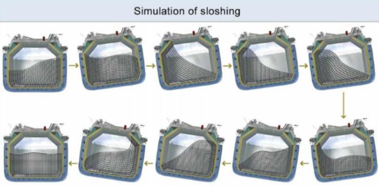
Following research, testing and improvements in tank design, sloshing criteria has changed slightly and the limits and barred range have been adjusted on new build membrane LNGCs.
Classification Societies, GTT and Marintek, carried out a series of model tests to investigate the effects of sloshing in partially filled prismatic LNG tanks. As a result of the tests, the following precautions should be taken to avoid damage due to sloshing:
- Cargo tank levels: The first precaution is to maintain the level of the tanks within the required limits i. e.:
- lower than a level corresponding to 10 % of the height of the tank for low fill conditions;
- higher than a level corresponding to normally 70 % of the height of the tank for fill conditions.
N. B. The Certificate of Fitness for the Carriage of Liquefied Gases, may show the lower limits as being 10 % of tank length, however this should be amended by Class in due course.
- ship’s movement: The second precaution is to try to limit the ship’s movements that generate sloshing in the tanks. The amplitude of sloshing depends on the condition of the sea (wave pattern), the trim and the speed of the ship. A minor alteration of course may change the ship motion considerably, particularly at high speed, and this may have a significant effect on sloshing.
The above limits will be stated within the ship specific cargo operating manual and could be included in the Conditions of Carriage section of the International Certificate of Fitness for the Carriage of Liquefied Gases in Bulk.
Non-Availability of Key Equipment
Reference: SIGTTO “LNG Shipping Suggested Competency Standards”, Sections:
1 Know and understand the procedures to be followed in the event of key equipment not being available.
The operator should consider the following regarding “key equipment” and its availability:
- when an item of essential equipment fails, despite having identical standby equipment, repair/replacement should be carried out as soon as possible so that designed redundancy is re-established in the shortest possible timeframe;
- if the safety of any operation is compromised due to key equipment failure(s), then that operation should not continue until a revised risk assessment has been conducted;
- in compliance with the ISM Code 8.1-8.3, the company should have contingency plans/drills in place to respond to an emergency situation brought about by the unavailability of key equipment (often referred to as “critical equipment”. The company must identify what exactly qualifies as “key equipment” and have in place an appropriate documented response to provide operator guidance in the event of failure;
- training and drills should be carried out regularly on the operation of key equipment and how to respond in the event of failure.
Loss of Gas Handling Capability
Reference: SIGTTO “LNG Shipping Suggested Competency Standards”, Sections:
1 Know and understand the effect upon the cargo tank condition when boil off gas cannot be processed in the machinery space:
- loaded and ballast conditions;
- tank pressure;
- cargo temperatures;
- cargo quality.
LNG contained in a ship’s cargo tanks vaporises due to external temperature changes passing through the insulation space and kinetic energy created by agitation of the cargo by the ship’s motion.
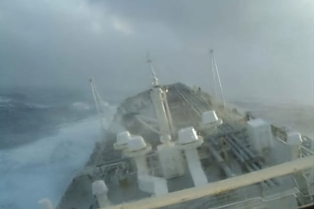
An example of agitation by the ship’s motion is in bad weather as the ship rolls, causing the surface area of the cargo to increase. This, in turn, creates more BOG and increases the cargo temperature. If the vapour cannot be consumed or the fuel gas handling capability was lost, the pressure could rise to a point where vapour would have to be vented to the atmosphere to prevent damage to the tanks.
The BOG naturally increases the cargo tank pressure, which reduces the quantity of BOG generated but increases cargo temperature. To prevent excessive pressure build up of BOG, and in accordance with the IGC Code, two independent safety valves (pilot operated relief valves) are installed on each tank. These safety valves prevent both excessive pressure (250 mbar) and negative pressure (minus 10 mbar) in the cargo tank.
A pressure control valve that is set at 230 mbar is fitted at the forward end of the vapour header and connects into the forward vent riser. Activation of this pressure control valve at 230 mbar reduces the possibility of emergency tank relief valves lifting.
This pressure control valve is fitted with the following settings:
- locked (for use in port);
- automatic – normal operations at sea or when not required by the Port Authority;
- manual – operator initiated.
In the unlikely event that a ship’s gas handling capability is completely lost, cargo conditioning can be managed by one of the following:
- use of a gas combustion unit (GCU), where fitted;
- use of an Liquefied Natural Gas Reliquefaction PlantLNG reliquefaction plant, where fitted;
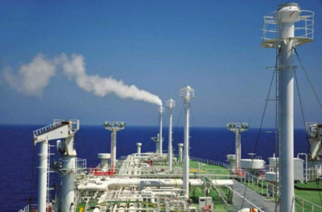
- cargo venting via the forward mast riser.
Venting is used only in extreme situations when tank pressure can not be maintained by the gas handling equipment.

Caution – it is essential that the vent mast is checked on a regular basis and drained of any accumulation of water.
An automatic valve on the common vapour header discharges to the forward vent riser, which has the capacity to handle the BOG under normal conditions. In addition, each tank is fitted with a manually operated vent valve (relief valve bypass) that discharges to the tank’s dedicated vent mast.
A problem could arise on arrival at the discharge port, as many countries do not permit venting within coastal waters. Compliance, without special dispensation, would require a period of maximum venting prior to arrival in an attempt to reduce the vapour header pressure to as low as can be safely achieved while Cooldown of Cargo System on the Liquefied Gas Carrierscooling down the tank temperatures as much as possible. The aim is to achieve vapour/liquid arm connection alongside without venting. Close cooperation between the ship, operators and port authorities is essential.
When venting, the following are to be observed at all times:
- wind direction relative to the accommodation;
- no smoking anywhere on the ship;
- accommodation to remain secured as far as possible at all times;
- accommodation ventilation system on full recirculation;
- weather watch/forecast maintained with regard to electrical storm activity;
- OOW fully aware of remote vent operation;
- on completion, N2 purging of vent mast to be carried out.
Prolonged Loss of Power to Cargo and Ancillary Systems
Reference: SIGTTO “LNG Shipping Suggested Competency Standards”, Sections:
1 Know the power supply arrangements for cargo equipment and ancillaries:
- emergency cables;
- soft starting equipment.
2 Know and understand the procedures and equipment for power supply to cargo equipment and ancillaries: capacity of emergency generator.
Regardless of the high voltage (HV) generated on board, when in IAS control the cargo pumps are started using a soft starter, usually one per cargo service switchboard. When the pumps are started locally at the switchboard, starting is direct on-line.
“Soft starting” provides a gradual run up of the drive motor and reduces high starting loads of the direct on-line type.
On a typical 6,6 kV power supply system, two 6,6 kV cargo switchboards supply the cargo pumps and H/D compressor. The other large motors and group starter panels are supplied from the 440 V main group starter panels directly and power for other smaller consumers is supplied through local group starter or distribution panels, from the 6,6 kV/440 V transformer.
Generally, each distribution circuit is protected against overcurrent and short circuit by protection relays or circuit breakers fitted on the appropriate switchboard, providing both inverse time overcurrent and instantaneous trips. A general service battery charging/distribution panel supplies the IAS, along with other essential low voltage services.
Each HV and LV supply system is provided with a trip/alarm device and a continuous monitoring facility that gives an audible and visual indication of abnormally low insulation levels to earth. A shore connection is provided at the emergency switchboard to supply power to the main and emergency 440 V switchboards, either independently or simultaneously.
The two cargo service switchboards are dedicated to cargo related auxiliaries. These switchboards are supplied from the 6,6 kV feeder panels of the main HV switchboard, with the 440 V switchboards supplied in turn via 6,6 kV/440 V step-down transformers.
Read also: Examples of the Emergency Situations with Liquefied Gas Carriers
Typically, each of the two 6,6 kV cargo service switchboards will supply the following consumers, half the cargo pumps (i. e. the port pump in each tank), one of the two HD compressors and the appropriate 6,6 kV/440 V step-down transformer.
The two cargo service switchboards supply an assortment of cargo related auxiliaries such as the LD compressor, half the spray pumps, HD/LD compressor LO pumps, compressor house exhaust fan, motor room supply fan, N2 generator feed air compressor, N2 generator system air heaters, etc.
The emergency diesel generator must be rated for use in an emergency or dry dock conditions. The generator feeds the emergency switchboard and the main switchboard through tie-breakers. The unit will start automatically should the main generator fail. It can also be started manually from either the engine control room or, locally, in the emergency generator room.
Under normal operating conditions the emergency switchboard is fed from the main switchboard through a tie-breaker, with the emergency generator start mode selector switch in the “auto” position at the starter panel and in the “remote” condition in the IAS. Under these conditions, a loss of voltage in the busbars will be detected and will initiate auto starting of the emergency generator.
Loss of Primary Containment
Reference: SIGTTO “LNG Shipping Suggested Competency Standards”, Sections:
1 Know and understand the procedures for cargo removal from insulation and hold spaces:
- how the leak is detected by:
- nitrogen purging;
- gas detectors;
- cold spot inspections.
- moss and IHI SPB tanks as appropriate by:
- drain plug;
- use of eductor: line-up and operation.
- membrane tanks by:
- tank piercing mechanism prior to discharge;
- use of compressor to remove cargo.
In the event of a cargo tank leakage there maybe a requirement for a ship to ship transfer or for the direct Jettison of cargo to the sea.
Loss of primary barrier on membrane type ship
In the event of mechanical damage (such as cargo pump failure) or over pressure of the primary barrier space (PBS), a failure of the primary membrane of a cargo tank may occur. The PBS will then be filled with LNG in a timescale proportional to the size and location of the membrane failure and the height of LNG in the cargo tank.
Detection of primary membrane failure
Experience has shown that, in a failure situation (not just a slow deterioration), the sequence of events regarding detection are:
- the LNG leakage vaporises rapidly as it enters the relatively warm environment of the primary (interbarrier) space. With the liquid/vapour phase change, the pressure in the space increases dramatically, activating associated high pressure alarms and lifting the space relief valves;
- as the permanent gas detection system cycles through its automatic programme, as soon as the affected primary space is selected, the gas analyser indication will alarm and associated “gas presence” alarms will activate;
- if the point of failure was in the vicinity of one of the temperature sensors for the insulation and/or inner hull steelwork, then it will also alarm fairly quickly after the event. Any time lapse would increase as the distance from the source of failure increases;
- finally, by visual cold spot inspection of the affected area of the inner hull.
Failure of the primary membrane that allows liquid cargo into the interbarrier space will be shown by:
- rapid rise in the methane level of the space;
- rapid rise in pressure, followed by continuous venting to atmosphere;
- lifting of the IBS relief valves;
- low temperature alarms initiating in all lower insulation temperature sensors;
- a reduction in the inner hull steel temperatures.
Removal of liquid from the primary (interbarrier) space
If this situation is determined, immediately segregate the gas contaminated primary barrier space (PBS) from the others and vent the damaged PBS to atmosphere to maintain the pressure at about 4 mbar (6 mbar below the PBS relief valves 10 mbar setpoint).
Increase the set pressure in the secondary barrier space (SBS) service header from its normal 2-3 mbar to 6 mbar. This higher pressure in the SBS should prevent gas contamination from the PBS should the secondary barrier not be completely tight.
As a precaution, immediately remove the flow cartridge and spring from the dynamic auto balancing valves on the affected tank to permit the glycol to flow at a higher rate to the coils in the Cofferdam – Definition and Pronunciationcofferdam and around the liquid dome. Increase the hull heating flow rate surrounding the affected tank as soon as the temperatures in the secondary barrier space or inner hull are observed to be dropping (colder).
Segregate and vent the damaged PBS:
- on the damaged tank, ensure that the PBS stays segregated from the SBS;
- shut the N2 supply valve to the PBS at the after end of the tank;
- open first the small manual vent valve on the forward transverse PBS header of the tank to try and control the pressure in the PBS of the damaged tank at 4 mbar. If that valve is not able to vent sufficient gas, then slowly open the large manual vent valve to maintain the pressure in the PBS at approximately 4 mbar. Throttle the small manual vent valve as required for fine control;
- log the PBS and SBS gas detection readings in the cargo operations log. If no gas is detected in the SBS, leave its N2 supply valve to the SBS open;
- on each intact tank, keep the valves set up as normal;
- continue to log the gas concentration on the PBS and SBS in each tank on an hourly basis initially, until the extent of the leakage to the damaged tank can be determined;
- if the gas concentrations in the intact tank’s PBS and SBS are not changing, then leave the N2 supply valves to those spaces unchanged;
- if the gas concentration in any of the intact tank’s PBS or SBS is increasing then immediately shut the N2 supply valve to the SBS of the damaged tank;
- at the first indication of gas in the SBS, immediately isolate the damaged tank’s SBS from the other SBS by shutting its N2 supply valve on the after end of the tank;
- check the pressure in the PBS and open the bypass vent valves as necessary to maintain the pressure at approximately 4 mbar (6 mbar below the 10 mbar setpoint of the relief valves);
- check the hull heating for the ballast tanks surrounding the damaged tank and operate as necessary.
As the cargo tanks are at a pressure of about 100 mbar higher than the PBS, the height of the LNG in the PBS could be about 0,5 m above that in the cargo tanks. If the cargo tank were pumped out with a head of liquid remaining in the PBS, severe damage to the primary membrane would result. For this reason, on some LNGCs, it may be necessary to intentionally puncture the primary membrane prior to the damaged cargo tank being pumped out. The cargo tank must be pumped out slowly enough to enable the level of any liquid contained in the PBS to fall at the same rate as the level in the cargo tank to prevent over pressurising of the primary membrane.
The fixed gas detection system for the PBS will alarm at an LEL reading of 30 % and, at this point, this will require investigation. The subsequent alarm setpoint for the SBS is at 60 % of LEL.
Barrier punching device
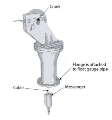
On NO96 membrane LNGCs a barrier punching device, termed a “messenger”, weighing 30 kg is kept on board for punching a hole through the primary membrane in the bottom of the tank. The “messenger” is inserted into the cargo tank float gauge standpipe on the trunk deck and allowed by gravity to fall through the LNG in the standpipe, punching through the membrane with its own weight. The “messenger” is designed to ensure it remains in the vertical position during its fall to the bottom of the tank. The bottom of the standpipe is fitted with a split perforated base to allow the messenger to penetrate through to the membrane. In systems where the barrier punch is utilised, the invar membrane directly beneath the standpipe is fitted with a thin diaphragm and the plywood insulation box cover is thinner than normal. This will allow the messenger to punch a clean hole of about 50 mm diameter through the primary membrane and box cover. This operation will be necessary only in the event that damage to the membrane has permitted LNG to accumulate as a liquid in the PBS, rising up the lower chamfer and sidewalls of the PBS.
The use of the barrier punching device is an extreme measure as it will flood the PBS with LNG. It should only be deployed after discussions with, and approval from, operators, GTT and Class.
Before using the punching device, notify the operating company GTT and Class of all the circumstances and obtain their approval.
The punching device should be used when pumping out the damaged cargo tank, ONLY if at least one of the following gives definite indication of liquid in the PBS:
- if liquid is indicated by all six of the bottom and lower chamfer thermocouples, and by any of the four thermocouples located above mid-height, the membrane should be punched at the start of the pumping operation;
- if liquid is indicated by all six of the secondary barrier thermocouples in the bottom and on the lower chamfer, but not on the two thermocouples located at about mid-height, it must be considered that some liquid will be present in the sidewalls and that the membrane should be punched when the tank level decreases to one-half full.
If liquid is not indicated by all four of the bottom thermocouples and by none of the lower chamfer or mid-height thermocouples, it is evidence that a head of liquid is not present in the sidewalls, therefore it is NOT necessary to use the punch device.
If the membrane has been punched, great care must be taken to ensure the liquid in the cargo tank is not pumped at a rate faster than gravity can drain the liquid from the insulation space. This is necessary to prevent localised over pressurisation, which will severely damage the membrane in those areas. The calculated rate by GTT is a maximum decrease in tank level of 0,4 m/h.
After the messenger punches the hole in the membrane and box cover, it must be removed (a retrieval line is attached prior to the messenger being deployed). This permits the liquid in the sidewalls to drain out by gravity through the punched hole, as the cargo tank level slowly decreases during the discharge of the tank. The remaining liquid trapped in the PBS can only be removed by evaporation during the warming up of the cargo tank.
It is imperative that the membrane punch device is installed and operated exactly as per the manufacturer’s instructions.
On LNGCs fitted with a Mark III Flex membrane system, a barrier punch is not used. In such cases, a portable liquid level measuring unit is available to assist in determining the height and size of the leak by recording the IBS level increase rate, IBS pressure and the cargo tank level and pressure. The portable liquid level measuring unit, designed to work even with a vacuum in the PBS, is left connected throughout the operation and manual level readings are taken hourly, recording the rate of LNG ingress (and eventual removal).
In the Mark III Flex membrane system, LNG in the IBS can be removed by either gravity drainage back into the cargo tank, as the tank is pumped out (this is the preferred method) or, if that does not work, LNG is removed using the IBS drainage system.
Before proceeding, the ship specific cargo operating manual should always be consulted and approval from the operators, GTT and Class obtained.
Generally, the procedure is as follows:
1 Gravity drainage
This is the preferred method and should be attempted first. If the break in the membrane is in, or near, the tank bottom and sufficiently large, then the LNG may drain back by gravity into the cargo tank as the tank contents are discharged. One cargo pump, operating at its rated capacity or a reduced capacity, may allow the level in the IBS to decrease at about the same rate as the level in the cargo tank. The portable liquid measuring device is utilised to monitor the level of LNG in the IBS and the cargo pump discharge rate is adjusted accordingly.
If it becomes apparent that the damage is either too small to allow the liquid in the IBS to drain back to the cargo tank at a reasonable rate, or if the membrane damage is high up in the tank, then it will be necessary to use the IBS drainage system.
2 IBS drainage system using the low duty compressor
If the LNG accumulated in an IBS will not drain by gravity fast enough to permit the cargo tank to be pumped out in a reasonable time, then it will be necessary to pump the liquid out of the IBS.
An LD compressor, the forcing vaporiser, the mist separator and the spray piping will be used to remove the liquid by drawing a sufficient vacuum in the IBS to lift the LNG from the IBS and into the spray header. From the spray header the LNG liquid will be directed to the forcing vaporiser, where it is vaporised to a temperature of approximately minus 40 °C (-40 °C). It then flows to the mist separator before the NG vapour is drawn into the LD compressor. The LD compressor then discharges the NG vapour to the fuel gas line to the consumers, the GCU or to atmosphere through the forward vent mast.
Loss of primary barrier on Moss type ship
Detection of cargo leakage from spherical tanks. A serious failure of the tank structure, allowing liquid into the annular space or hold space, will be indicated by:
- a rapid increase in the methane content of the affected space;
- low temperature alarms at the temperature sensors in the surrounding areas;
- a general lowering of the inner hull steel temperatures;
- possible liquid alarms in the surrounding areas;
- possible gas alarms in the surrounding areas.
Any liquid collecting in the affected hold’s drip pan will raise a liquid alarm via the IAS. Whether that liquid is LNG cargo from tank leakage, or water due to leakage from the ballast tanks, is determined by observing the gas detector and temperature sensors.
If leakage of cargo into the hold space is confirmed, the O2 content of this space must be reduced to below the explosive limit using the IG plant or nitrogen. IG or N2 is introduced via the hold space aeration header to the bottom of the space and is exhausted to atmosphere from the tank top. Connection to the appropriate flange on the vent riser and the hold space manual vent valve situated on the tank top is made with a dedicated cargo hose. Inerting continues until the O2 content, as measured at the outlet pipe sample point, remains below 1 %.
Procedure for removal of cargo leakage on Moss type ships. Depending on the severity of the leakage, the leakage may be removed from the drip pan using a dedicated eductor that is driven by the spray pump and returned to the cargo tank via appropriate cryogenic hoses.
Ballast Tank Leakage into Containment Space
Reference: SIGTTO “LNG Shipping Suggested Competency Standards”, Sections:
1 Know and understand the action to be taken in the event of ballast tank leakage in the containment space:
- protection of secondary barrier;
- action to prevent freezing;
- reduction of ballast tank level.
On LNGCs, ballast water leakage from the Strategies and Best Practices of Ballast Voyage for Liquefied Gas Carriersadjacent ballast tanks can occur through fractures in the inner hull plating. If the leakage remains undetected and water accumulates in these spaces, ice can form. In the insulation spaces on membrane LNGCs, ice accummulation, or the head of water build up, can progress to cause deformations and possibly rupture of the tank insulation. The resultant cold conduction paths in the insulation may cause cold spots to form.
In the annular space on Moss type LNGCs, ice accumulation can progress to cause deformations and possibly rupture of the tank insulation. The resultant cold conduction paths in the insulation may cause cold spots to form. To reduce the risk of damage from water ingress, each cargo tank hold space on Moss type LNGCs and each insulation space on membrane LNGCs are provided with water/leakage detection units.
Ballast tank leakage into containment space – membrane ship
Ballast water ingress detection. The leakage protection system includes a method of collecting and accumulating water as well as small leaks of liquid cargo.
At the bottom of each cofferdam there are two bilge wells extending into the pipe duct. One bilge well serves the cofferdam and the other bilge well, which is a sealed unit, serves the aft end of each cargo tank insulating space. Insulation space liquid leakage (generally ballast water) collects in the sealed bilge well, where water detection equipment is installed. Typically, four detections units are fitted, two in use and two spares. In some cases float alarms are fitted as a back-up to the conductivity cell type detectors. In the event of liquid being detected an alarm will sound and the IAS display will show the source of the alarm. If the alarm sounds, it must be investigated and appropriate action taken.
Each detector is of the conductivity cell type, which causes a change in resistance and activates an alarm in the presence of humidity from the ingress of liquid. The bilge well serves as the inlet for the N2 supply pipe to the insulation space. This N2 supply pipe also acts as a manual sounding pipe to the bilge well.
Where available, a portable liquid level gauge can be connected to the sounding pipe to give an indication of the liquid level in the insulated space. Gas detectors are installed in the pipe duct and cofferdams.
An example of insulation spacewater discharge
Each sealed bilge well is connected to a 50 mm draining pipe system, with pneumatic pumps situated in the pipe duct. In the event of ingress, pumps discharge any accumulated water to deck level and then overboard using a flexible hose.
If it is suspected that water has leaked into an insulation space, the following applies:
- pump out the ballast water from the adjacent wing tank after checking the stability on the ship’s loading computer;
- ventilate the pipe duct space, which runs beneath the cargo tanks and the cofferdam and carry out normal enclosed space safety procedures before entry;
- connect a flexible hose to the pneumatic pump outlet valve to drain the water discharge overboard;
- open the bilge well outlet valve on the selected tank insulation space;
- open the inlet and outlet valves on the selected pump;
- open the air supply to the pump and continue pumping until the maximum amount of water has been discharged;
- carry out an inner hull inspection to determine the cause of the leak (with particular reference to safe atmosphere in the ballast tank space).
After the maximum possible amount of water has been discharged from this insulation space, moisture will still remain in the insulation space and over the bottom area.
Increasing the flow of N2 through the space can assist in drying out the insulation before any cargo is carried in the affected tank. This should be continued until the moisture level is no longer detected by the water detection system.
An enclosed space entry permit and a permit to work (PTW) will be required before entering for any inspection.
The process will vary according to the equipment fitted on each ship.
Ballast tank leakage into containment space – Moss type ship
To reduce the risk of damage from leakage, each cargo tank hold space is provided with water/leakage detection units.
The leakage protection system also includes a method of collecting and accumulating small leaks of liquid cargo as well as water. The water is collected in the bilge rose box (sump) situated at the after end of the hold space under the cargo tank. The water leakage collects in this sump, where the monitoring equipment is installed. The equipment is used as both a liquid indicator and a temperature indicator to raise alarms in the CCR via the IAS. Gas detectors are situated in different areas of the hold space.
Whether the liquid is LNG due to a cargo tank leakage, or water due to leakage from the water ballast tanks, can be determined by observing the gas detector and the temperature indicators. A low temperature of minus 100 °C (-100 °C) to minus 163 °C (-163 °C) indicates cargo leakage, while temperatures above 0 °C indicate water leakage.
An example of the procedure for removal of water from a hold space. An eductor is installed in the sump to empty the area when required. If the hold space has to be emptied of water, the procedure is:
- check water levels in adjacent ballast tanks. If leakage is severe, check the stability on the ship’s loading computer before reducing the ballast tank level;
- remove the blank flange covering the eductor discharge on the main deck;
- set up the fire and bilge pump to supply drive water to the eductor supply line;
- open the eductor inlet valve;
- start the fire and bilge pump. Water is removed from the hold’s sump and discharged overboard;
- on completion, shut the inlet valve to the eductor and refit the blank flange;
- carry out a hold space inspection to determine the cause of the leak (ensuring a safe atmosphere in the space before entering).
After the maximum possible amount of water has been discharged from the hold, moisture will still remain over the bottom area. Running the dry air plant and purging the hold space will assist in drying the area. The process will vary according to the equipment fitted on each ship.
Nitrogen Supply Failure
Reference: SIGTTO “LNG Shipping Suggested Competency Standards”, Sections:
1 Know and understnad their alarm settings and resulting actions:
- consequences of loss of nitrogen supply on operations.
N2 supply failure or prolonged period of disruption
If the reservoir of N2 in the buffer tanks becomes depleted and the pressure begins to fall significantly, then consumers requiring a continual supply to maintain a working N2 pressure would start to trip as protection circuits activate, or manual intervention stops the equipment for safety reasons before tripping levels are reached. Consumers affected in this way would be:
- HD/LD compressors under the influence of compressor sealing low-low N2 pressure and bulkhead sealing low-low N2 pressure;
- fuel gas supply to the boilers due to low-low N2 purge pressure;
- if cargo operations were underway, an ESD trip would be initiated by loss of N2 pressure.
Over time, atmosphere integrity around membrane cargo tanks, or the annular space around spherical tanks, would be threatened as the N2 pressures dissipated. In the event of a riser fire, the N2 snuffing facility would be unavailable unless a buffer tank had been isolated after pressurisation.
Jettison of Cargo
Reference: SIGTTO “LNG Shipping Suggested Competency Standards”, Sections:
1 Know and understand the procedures:
- how LNG will behave when discharged onto the sea;
- safety procedures to be implemented;
- pipeline “line-up” requirements;
- operation of cargo pumps to maximise efficiency but minimise risk.
As jettisoning of LNG will create hazardous conditions, the following must be considered by the Master beforehand:
- Has the operating company been fully appraised of the situation and has permission to proceed been given (where possible)?
- Where appropriate, has communication with local authorities (depending on location) and other parties involved in any ongoing operation been made?
- Weather conditions, and the heading of the ship relative to the wind, so that the jettisoned liquid and resultant vapour cloud will be carried away from the ship. Avoid blanketing the vapour with exhaust gases from the funnel if possible.
- Full risk assessment for the proposed jettisoning of cargo.
- Safety briefing for all personnel involved.
- Rigging of al I equipment necessary for the jettisoning.
- Has all required fire-fighting equipment (portable and permanent) been made ready?
- Are all accommodation and external doors must be closed and air conditioning units switched to recirculation?
- The no smoking rule (anywhere on the ship) must be rigidly enforced.
- Monitoring of gas concentrations on all deck areas.
- Is the water curtain on the side of the jettison running to protect the ship’s structure (consider deck and spray system in operation)?
- Issuing a “securite” message to other shipping in the vicinity.
The discharge rate must be limited to the capacity of one cargo pump only and, if necessary, this should be reduced to allow acceptable dispersal within the limits of the prevailing weather conditions.
It is essential to be aware that jettisoning LNG may impact the immediate environment around the ship.
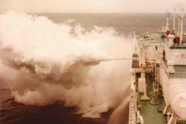
A large vapour cloud will be generated and, as it travels, it will create a significant hazard until dissipation due to warming-up in the atmosphere at approximately minus 110 °C (-110 °C).
Too rapid a flow of LNG will create a rapid phase transfer (RPT) as the liquid hits the seawater. This violent reaction and increase in gas vapour as the liquid LNG contacts the surface of the sea produces a very cold cloud of dense vapour that will not disperse readily from the immediate vicinity of the ship.
Overfilling of a Cargo Tank
Reference: SIGTTO “LNG Shipping Suggested Competency Standards”, Sections:
1 Know the means by which the alarm is raised for cargo tank high level:
- level gauging system;
- independent protection devices.
2 Know and understand the procedures to be followed in the event of overfilling a cargo tank:
- high-high level shutdown;
- transfer of cargo.
Cargo tank level is transferred from the CTMS to the IAS. The IAS compares the level with a preset value (e. g. 98,5 %)and if the cargo tank level is higher than this without override selection, the filling valve will be automatically closed by the tank protection system (TPS) and the operator cannot then manipulate this valve from the IAS.
Procedure in the event of cargo tank overfilling
If the cargo level in any tank is allowed to reach “extreme high level”, as sensed by the independent sensors (float or radar type), then an ESD trip is initiated. This will result in closure of the manifold ESD valves and trip the associated equipment.
If there is an ESD1, the compressors would trip and there may be an issue of managing the vapour pressure.
When the ESD1 is activated, a reciprocal trip is electronically dispatched ashore via the electrical or fibreoptic link. This stops all of the loading pumps in the terminal.
Assuming that the topping-off procedure has not been fully completed, cargo from the overfilled tank must be transferred internally into the other slack tanks to re-establish a normal fill level. To start a cargo pump with an ESD1 trip active, the appropriate blocking circuits must be engaged on the overfilled tank only. Manifold valves remain closed and the whole operation must be coordinated with the terminal. All internal cargo transfer precautions must be put in place, with observers/operators out on the cargo deck as well as in the CCR.

Before using the blocking switch, determine exactly what has caused the shutdown. Before using the blockswitch, turn the controls for all crossover valves to the shut position. Use the blocking switch only when absolutely necessary to recover from an emergency condition. When the emergency condition is corrected, immediately restore the shutdown system to normal.
Note: procedures for “blocking”, including who can initiate “blocking”, should be established and posted in the CCR.
Loss of Cargo Pipeline Containment
Reference: SIGTTO “LNG Shipping Suggested Competency Standards”, Sections:
1 Know and understand the action to be taken in the event of leakage from a cargo pipeline or valve:
- liquid cargo lines;
- vapour cargo lines.
Liquid cargo line leakage
Discovery. LNG leakage of any size must not be ignored, no matter how small, when pipelines and valves are tight and intact. Watch keeper vigilance and regular rounds are imperative, especially while engaged in cargo operations.
Report. Prompt reporting of any liquid leakage to the CCR is vitally important. Radio communication and a robust reporting procedure are essential.
Response. The response should consider:
- that protection of any steelwork in the area and isolation of the leak are the main objectives;
- personnel must remain at a safe distance and the immediate vicinity should be cordoned off;
- firehoses can be utilised from a safe distance to provide essential protection for the steelwork. In more severe cases the IMO spray system can be activated;
- the valves required to isolate the leakage should, where possible, be operated remotely. If severe leakage occurs when engaged in cargo operations, then initiating an ESD1 trip using the nearest manual button may be appropriate;
- terminal control should be kept updated throughout;
- an announcement should be made by the OIC ensuring all personnel are aware of the current hazardous situation. The OIC should also initiate the ship’s internal response plan appropriate for an uncontrolled release of liquid cargo;
- a timely response is required to avoid being faced with a rapidly deteriorating situation. Any liquid leak is always accompanied by the additional hazard of the resulting vapour, which also requires an appropriate response.
Vapour line leakage
Generally, the considerations for liquid cargo line leakage apply. In the event of a large uncontrolled vapour release, the following additional considerations apply:
- accommodation security:
- all entrances must be closed;
- the A/C changed over to the full recirculation mode;
- smoking restrictions rigorously enforced everywhere on board;
- an announcement should be made by the OIC ensuring all personnel are aware of the current hazardous situation;
- accommodation water spray curtain activated;
- movement of the developing vapour cloud monitored, particularly with regard the engine room intakes;
- response teams may consider vapour cloud displacement by using firehoses set at full spray;
- the entire visible vapour plume should be considered as flammable;
- the ship’s heading should be adjusted according to the prevailing weather conditions.
Flanges should be checked for tightness prior to loading, particularly prior to 1st loading or after dry-dock.
Failure of Integrated Automation System
Reference: SIGTTO “LNG Shipping Suggested Competency Standards”, Sections:
1 Know and understand the procedures for failure of the system:
- local instrumentation;
- manual local starting and stopping of equipment;
- manual local control of equipment and systems.
From a cargo perspective, priority in the event of loss of the IAS is vapour pressure control. In this event, the ship still has local gauges and instrumentation, local start/stop of equipment and local valve operation.
Monitoring system/IAS failure
Prolonged operation of the LNGC without the IAS is not an option. Some equipment normally controlled by these systems can be manually operated in emergency situations, i. e. provision for firing the boilers manually and locally is a facility common to all ships. This does not mean, however, that the entire cargo or machinery plant can be operated safely for a prolonged period without the IAS in its entirety. For example, the reliquefaction plant can only be operated through the IAS. Interlocks, limited number of personnel on board and the large distances between items of critical equipment make the IAS a necessity. Efforts must always be directed at re-establishing IAS control.
In the event of problems with/failure of the IAS, remote support should be obtained from the manufacturers.
Uncontrolled Release of Cargo
Reference: SIGTTO “LNG Shipping Suggested Competency Standards”, Sections:
1 Know and understand the procedures to be followed in the event of uncontrolled release:
- accommodation ventilation recirculation;
- extinguishing all hot work and naked flames throughout vessel;
- relative wind;
- vapour cloud drift;
- additional isolation valves;
- reduction of cargo tank pressure;
- nitrogen snuffing of risers.
Emergency procedures for the uncontrolled release of cargo will be set out in the cargo operating manual and the ship’s SMS. Personnel should be familiar with the actions to take in the event of an uncontrolled release of LNG.
The dangers of an uncontrolled release are similar to that for a controlled release (see “LNG jettisoning” above) where vapour cloud drift poses a risk to the environment and personnel. Vapour cloud drift will depend on several factors, including ship speed and relative wind.
A typical response may be as follows:
- alert and, depending on the severity, sound the general alarm. This is typically activated from the CCR or bridge;
- response teams muster and commence donning appropriate equipment, i. e. fire/cold suits, SCBA, etc.;
- activate IMO spray system and provide firehose protection for the affected steelwork as appropriate. Activated from the bridge or CCR, the drenching system provides copious water coverage of the steelwork threatened by cold contact from an LNG leak. Spray selection can be carried out later as appropriate;
- establish control, briefing the response teams as soon as possible. A prompt and clearly defined response is the main objective;
- isolate the source of the uncontrolled release, as far as possible by remote operation of associated valves. Ship’s drawings and overlays may be required to fully establish all lines/systems that require isolation;
- if at sea, any associated cargo operations must be terminated, i. e. spraying, etc. Such operations generate considerable vapour and so increase tank pressures, which may further exacerbate the problem;
- fuel gas burning terminated if appropriate. Careful consideration is required regarding this action because continued gas burning is a means of, cargo tank pressure reduction;
- ESD1 trip activated if alongside with the ship engaged in cargo operations. Again, be prepared for a possible increase in the cargo tank pressure as the vapour ESD manifold valve closes;
- ship’s course adjusted to provide most favourable conditions with regard to keeping the methane cloud relative to the ship at a safe location, i. e. especially important to keep it as far from the funnel as possible. Remember as a very rough guide, the flammable limits of the vapour cloud coincide with the visible limits of the white plume, i. e. an over rich atmosphere exists inside the cloud and too lean conditions at a short distance from the plume;
- accommodation must be secured by changing air conditioning over to full recirculation mode and closing all entrances;
- a PA announcement alerting all personnel if the general alarm was not sounded;
- smoking and naked flame restrictions, i. e. not anywhere on board. E/R informed and suspension of hot work notices posted;
- the condition of the cargo can be adjusted to minimise the effect of the uncontrolled release, i. e. cargo tank pressure reduced by whatever means remain available;
- fire response measures must be considered and planned for;
- operating company/terminal should be informed and kept appraised of the situation.
Should an uncontrolled release of cargo be passing up the mast riser, caution should be exercised and the mast riser N2 snuffing system be prepared in the event that fire may occur.

- The international group of liquefied natural gas importers (GIIGNL). LNG custody transfer handbook / 6th Edition: 2020-2021.
- ©Witherby Publishing Group Ltd. LNG Shipping Knowledge / 3rd Edition: 2008-2020.
- CBS Publishers & Distributors Pvt Ltd. Design of LPG and LNG Jetties with Navigation and Risk Analysis / 4th Edition.
- NATURAL GAS PROCESSING & ITS ENERGY TRANSITION ROLE: LNG, CNG, LPG & NGL Paperback – Large Print, November 14, 2023.
- OCIMF, ICS, SIGTTO & CDI. Ship to Ship Transfer Guide for Petroleum, Chemicals and Liquefied Gases / 1st Edition, 2013.
- The Society of International Gas Tanker and Terminal Operators (SIGTTO). Ship/Shore Interface / 1st Edition, 2018.