Natural Gas Dehydration is a fundamental process in the midstream oil and gas industry. Natural gas, whether associated, non-associated, or tail gas from sweetening, typically contains water in both liquid and vapor forms upon extraction. This moisture must be effectively removed to meet stringent sales and pipeline specifications, commonly requiring a maximum water content of 7 lb H2O per MMscf.
The primary drivers for water removal are the prevention of solid hydrate formation, which can cause severe blockages in pipelines and equipment, and the mitigation of internal corrosion and slug flow resulting from condensed water. While simple separators remove free liquid water, eliminating the dissolved water vapor requires a complex treatment known as “dehydration“, which involves lowering the gas’s dew point temperature. The industry relies mainly on two mass transfer methods: liquid desiccant dehydration (e. g., using Triethylene Glycol or TEG) and solid desiccant dehydration (e. g., using molecular sieves). This article details the principles, design considerations, and operational challenges of these essential processes.
Introduction
Natural, associated, or tail gas usually contains water, in liquid and/or vapor form, at source and/or as a result of sweetening with an aqueous solution. Operating experience and thorough engineering have proved that it is necessary to reduce and control the water content of gas to ensure safe processing and transmission. The major reasons for removing the water from natural gas are as follow.
- Natural gas in the right conditions can combine with liquid or free water to form solid hydrates that can plug valves fittings or even pipelines.
- Water can condense in the pipeline, causing slug flow and possible erosion and corrosion.
- Water vapor increases the volume and decreases the heating value of the gas.
- Sales gas contracts and/or pipeline specifications often have to meet the maximum water content of 7 lb H2O per MMscf.
Pipeline drips installed near wellheads and at strategic locations along gathering and trunk lines will eliminate most of the free water lifted from the wells in the gas stream. Multistage separators can also be deployed to ensure the reduction of free water that may be present. However, removal of the water vapor that exists in solution in Liquefied Natural Gas Carrier Market Insightsnatural gas requires a more complex treatment. This treatment consists of “dehydrating” the natural gas, which is accomplished by lowering the dew point temperature of the gas at which water vapor will condense from the gas.
There are several methods of dehydrating natural gas. The most common of these are liquid desiccant (glycol) dehydration, solid desiccant dehydration, and refrigeration (i. e., cooling the gas). The first two methods utilize mass transfer of the water molecule into a liquid solvent (glycol solution) or a crystalline structure (dry desiccant). The third method employs cooling to condense the water molecule to the liquid phase with the subsequent injection of inhibitor to prevent hydrate formation. However, the choice of dehydration method is usually between glycol and solid desiccants. Each of these methods is discussed in this chapter. Refrigeration technology is also discussed in article “Natural Gas Processing and Liquids RecoveryNatural Gas Liquids Recovery“.
Several other dehydration technologies (i. e., membranes, vortex tube, and supersonic processes) are used less commonly and are not discussed here. There are also many commercially available processes for customized dehydration systems. These types of processes (i. e., IFPEXOL) or solvents (i. e., Selexol) are often designed to enhance conventional equipment performance. However, the suitability of these processes should be evaluated on a case-specific basis.
Water Content Determination
The first step in evaluating and/or designing a gas dehydration system is to determine the water content of the gas. This datum is most important when one designs sour gas dehydration facilities and estimates water production with sour gas in the plant inlet separator. For most Inert Gas Systems – Design, Operation, Control Mechanismsgas systems the McKetta and Wehe chart, generated from empirical data, provides the standard for water content determination. This chart can be used to predict the saturated water content of sweet, pipeline quality natural gas. There are also several methods available for determining the water content of sour natural gas at saturation. In general, for acid gas concentrations less than about 30 %, existing methods are satisfactory. For higher acid gas concentrations (above 50 %), particularly at higher pressures, existing methods can lead to serious errors in estimating water contents. An appropriate method has been introduced by Wichert and Wichert. It is chart based and provides good estimates of the equilibrium water vapor content of sour natural gas for a range of conditions, including H2S contents of 3-38 mole % with CO2 contents of 3-43 mole %, pressures from 290 to 10 153 psia, and temperatures from 50 to 347 °F. The overall average error of this method is less than 1 %. However, a few points showed a discrepancy of more than ±10 %. To estimate the water content of sour gas:
1 Determine the equilibrium water vapor content of sweet gas at the operating temperature and pressure conditions using Figure 1.
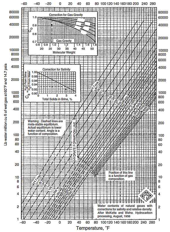
2 Determine the mole % H2S equivalent concentration of the sour gas as:
3 From Figure 2 at the bottom left-hand temperature scale, move to the right to the mole % H2S equivalent (interpolate between the lines if necessary).

4 From this point, move to the upper chart, to the pressure of interest. From the pressure point, move to the left, to the ratio scale.
5 Multiply the value from step 4 by the water content determined for sweet gas in step 1. The result is the estimate of the saturated water content of the sour gas at the pressure and temperature of interest.
Water content calculations based on proprietary/literature equations of state (EOS) are also common. Equation of state methods typically overestimate the water content for higher acid gas concentrations, particularly at higher pressures, when compared to experimental data.
Glycol Dehydration
Among the different gas drying processes, absorption is the most common technique, where the water vapor in the gas stream becomes absorbed in a liquid solvent stream. Glycols are the most widely used absorption liquids as they approximate the properties that meet commercial application criteria. Several glycols have been found suitable for commercial application.
The commonly available glycols (see section Navigating Acid Gas Treating and Sulfur Reclamation“Physical Properties of Fluids”) and their uses are described as follows.
- Monoethylene glycol (MEG); high vapor equilibrium with gas so tend to lose to gas phase in contactor. Use as hydrate inhibitor where it can be recovered from gas by separation at temperatures below 50 °F.
- Diethylene glycol (DEG); high vapor pressure leads to high losses in contactor. Low decomposition temperature requires low reconcentrator temperature (315 to 340 °F) and thus cannot get pure enough for most applications.
- Triethylene glycol (TEG); most common. Reconcentrate at 340-400 °F, for high purity. At contactor temperatures in excess of 120 °F, there is a tendency to high vapor losses. Dewpoint depressions up to 150 °F are possible with stripping gas.
- Tetraethylene glycol (TREG); more expensive than TEG but less loss at high gas contact temperatures. Reconcentrate at 400 to 430 °F.
TEG is by far the most common liquid desiccant used in natural gas dehydration. It exhibits most of the desirable criteria of commercial suitability listed here.
- TEG is regenerated more easily to a concentration of 98-99 % in an atmospheric stripper because of its high boiling point and decomposition temperature.
- TEG has an initial theoretical decomposition temperature of 404 °F, whereas that of diethylene glycol is only 328 °F
- Vaporization losses are lower than monoethylene glycol or diethylene glycol. Therefore, the TEG can be regenerated easily to the high concentrations needed to meet pipeline water dew point specifications.
- Capital and operating costs are lower.
Natural gas dehydration with TEG is discussed under the following topics: process description and design considerations.
Process Description
In this section, dehydration of natural gas by TEG is first outlined by summarizing the flow paths of natural gas and glycol. Then the individual components of a typical TEG unit are described in detail. As shown in Figure 3, wet natural gas first typically enters an inlet separator to remove all liquid hydrocarbons from the gas stream.

Then the gas flows to an absorber (contactor) where it is contacted countercurrently and dried by the lean TEG. TEG also absorbs volatile organic compounds (VOCs VOC emissions are an environmental challenge for the natural gas industry, hence glycol dehydration systems require monitoring and control of VOC emissions.x) that vaporize with the water in the reboiler. Dry natural gas exiting the absorber passes through a gas/glycol heat exchanger and then into the sales line. The wet or “rich” glycol exiting the absorber flows through a coil in the accumulator where it is preheated by hot lean glycol. After the glycol-glycol heat exchanger, the rich glycol enters the stripping column and flows down the packed bed section into the reboiler. Steam generated in the reboiler strips absorbed water and VOCs out of the glycol as it rises up the packed bed. The water vapor and desorbed natural gas are vented from the top of the stripper. The hot regenerated lean glycol flows out of the reboiler into the accumulator (surge tank) where it is cooled via cross exchange with returning rich glycol; it is pumped to a glycol/gas heat exchanger and back to the top of the absorber.
Read also: Time Based Heat Transfer
The simple flow diagram shown in Figure 3 is typical of small gas dehydration units where unattended operation is the prime concern. Larger units are monitored daily and the efficiency and operational cost are improved by the additional equipment, shown in Figure 4, where:
- Rich glycol leaves the absorber and enters a cooling coil that controls the water reflux rate at the top of the stripper. This temperature control ensures that the water vapor leaving the still does not carry over excess glycol.
- Heat exchange between the cool rich glycol and the hot lean glycol is improved by using two or more shell and tube heat exchangers in series. The increased heat recovery reduces fuel consumption in the reboiler and protects the glycol circulation pump from being overheated, it also allows the flash tank and filter to operate at approximately 150 °F. Higher flash temperatures will ensure maximum entrained gas to be removed from the rich TEG.
- Rich glycol is flashed to remove dissolved hydrocarbons. The latter can be used for fuel and/or stripping gas.
- The rich glycol is filtered before being heated in the reconcentrator. This prevents impurities such as solids and heavy hydrocarbons from plugging the packed column and fouling the reboiler fire tube.

Design Considerations
More detailed information about each equipment operation and design used in a TEG dehydration unit is described as follow.
Absorber (Contactor)
The incoming wet gas and the lean TEG are contacted countercurrently in the absorber to reduce the water content of the gas to the required specifications. (In an ethylene glycol system, glycol is injected directly into the The Resurgence of Liquefied Natural Gas in the Atlantic Basin and Qatarnatural gas stream; therefore, an absorber is not used.) The key design parameters for the absorber are:
- Gas flow rate and specific gravity.
- Gas temperature.
- Operating pressure (gas pressure).
- Outlet dew point or water content required.
The amount of water to be removed in a TEG system is calculated from the gas flow rate, the water content of incoming gas, and the desired water content of outgoing gas. The water removal rate, assuming the inlet gas is water saturated, can be determined as:
where:
- Wr – is water removed, lb/hr;
- Wi – is water content of inlet gas, lb/MMscf;
- Wo – is water content of outlet gas, lb/MMscf;
- and QG – gas flow rate, MMscfd.
The glycol circulation rate is determined on the basis of the amount of water to be removed and is usually between 2 and 6 gallons of TEG per pound of water removed, with 3 gallons TEG/lb water being typical. Higher circulation rates provide little additional dehydration while increasing reboiler fuel and pumping requirements. Problems can arise if the TEG circulation rate is too low; therefore, a certain amount of overcirculation is desired. An excessive circulation rate may overload the reboiler and prevent good glycol regeneration. The heat required by the reboiler is directly proportional to the circulation rate. Thus, an increase in circulation rate may decrease reboiler temperature, decreasing lean glycol concentration, and actually decrease the amount of water that is removed by the glycol from the gas. Only if the reboiler temperature remains constant will an increase in circulation rate lower the dew point of the gas. An overly restricted circulation rate can also cause problems with tray hydraulics, contactor performance, and fouling of glycol-to-glycol heat exchangers. Therefore, operators should include a margin of safety, or “comfort zone“, when calculating reductions in circulation rates.
An optimal circulation rate for each dehydration unit typically ranges from 10 to 30 % above the minimum circulation rate (EPA430-B-03-013).
The minimum glycol circulation rate can then be calculated as:
where:
- QTEG, min – is the minimum TEG circulation rate (gal TEG/hr);
- and G – is the glycol-to-water ratio (gal TEG/lb water removed).
The industry accepted rule of thumb is 3 gallons of TEG per pound of water removed.
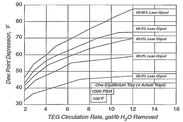
Figure 5 shows the effect of TEG concentration and circulation rate on dew point depression for a fixed amount of absorber contact. Note that the curves become relatively flat at high circulation rates.
The diameter of the absorber and the number of absorber stages are selected on the basis of the gas and glycol flow rates and gas-specific gravity. The diameter of the contactor (absorber) can be estimated from the Souders and Brown correlation as follows.
where:
- D – is internal diameter of glycol contactor, ft;
- QG – is gas volumetric flow rate, ft3/hr;
- Vmax – is maximum superficial gas velocity, ft/hr;
- KSB – is Souders and Brown coefficient, ft/hr;
- ρL – is glycol density, lb/ft3;
- and ρG – is gas density at column condition, lb/ft3.
Traditionally, the glycol absorber contains 6-12 trays that provide an adequate contact area between the gas and the glycol.
The more trays, the greater the dew point depression for a constant glycol circulation rate and lean glycol concentration. Conversely, specifying more trays with the same TEG concentration, a lower circulation rate is required. By specifying more trays, fuel savings can be realized because the heat duty of the reboiler is directly related to the glycol circulation rate.
Although either bubble cap trays or valve trays may be used, some operators prefer bubble cap trays because they are suitable for viscous liquids, handle high turndown ratios and low liquid/gas ratios well, and are not subject to weeping. Calculated tray efficiency values are dependent on the TEG/water equilibrium data used. To achieve an accurate design method, column efficiencies consistent with accurate equilibrium data must be therefore recommended. There are still uncertainties in equilibrium data for the TEG/water/natural gas system. However, when using accurate equilibrium data, an overall bubble cap tray efficiency of 40-50 % and a Murphree The Murphree tray efficiency (for tray number n) is defined as (the mole fraction in the gas from tray n – the mole fraction from the tray below)/(the mole fraction in equilibrium with the liquid at tray n – the mole fraction from the tray below).x efficiency of 55-70 % can be expected at normal absorption conditions, 86 °F and 99-99,5 % wt TEG. Earlier, overall tray efficiencies between 25 and 40 % have been recommended for design.
It will be interesting: Cargo Containment System of Gas Vessel
This is regarded as too conservative. It has been suggested that using 50 % Murphree efficiency based on accurate phase equilibrium data should give a conservative design at normal high-pressure dehydration conditions.
The standard tray spacing in glycol contactors is 24 inches; closer spacing increases glycol losses if foaming occurs because of greater entrainment. The total height of the contactor column will be based on the number of trays required plus an additional 6-10 ft to allow space for a vapor disengagement area above the top tray and an inlet gas area at the bottom of the column.
One option to the trayed TEG contactor is the use of structured packing. Structured packing was developed as an alternative to random packing to improve mass transfer control by use of a fixed orientation of the transfer surface. The combination of high gas capacity and reduced height of an equilibrium stage, compared with trayed contactors, makes the application of structured packing desirable for both new contactor designs and existing trayed-contactor capacity upgrades. Hence, the structured packing may offer potential cost savings over trays. A detailed discussion on calculating column diameter and the required packing height is given by Ghoshal and Mukhopadhyay.
The absorber is usually vertical to allow proper glycol flow with sufficient gas/liquid contact and operates at the pressure of the incoming gas. A demister pad or mist eliminator at the top of the absorber or a Phase Separation: An Essential Process in Hydrocarbon Productionseparator vessel following the absorber can reduce glycol losses by preventing glycol from being carried out with the dry gas.
Still (Stripper)
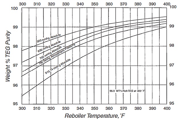
The still or stripper column is used in conjunction with the reboiler to regenerate the glycol. On many dehydrators, the still is placed vertically on top of the reboiler so that vapor from the reboiler directly enters the bottom of the distillation column. A given lean TEG concentration is produced in the reboiler and still column (regenerator) section by the control of reboiler temperature, pressure, and the possible use of a stripping gas. As shown in Figure 6, the reboiler temperature controls the concentration of the water in the lean glycol. Reboiler temperatures for TEG are limited to 400 °F, which limits the maximum lean glycol concentration without stripping gas. Some operators limit the reboiler temperature to between 370 and 390 °F to minimize degradation of the glycol. This effectively limits the lean glycol concentration to between 98,5 and 98,9 %.
There are improved regeneration techniques that have higher glycol concentration and, therefore, lower treated gas dew points. By injecting dry (stripping) gas into the base of the glycol reboiler in order to:
- strip off water vapor from the glycol by reducing the vapor partial pressure;
- and agitate the glycol to accelerate the release of water vapor, TEG concentration increases from 99,1 to 99,6 % by weight.
A dry gas injection process can be enhanced using a packed column of countercurrent gas stripping, which increases the capability of TEG for gas dehydration by reconcentrating the glycol to as high as 99,6 %. The Drizo process, developed by Dow Chemical Co., also uses hydrocarbon solvents as azeotropic stripping agents for improving trace quantities of water in the TEG. The process performs a tertiary azeotropic distillation, resulting in glycol concentrations to 99,9 %. This process avoids flaring stripping gas and reduces operating costs. Other patented processes in use to enhance the glycol purity and thereby achieve a more stringent water dew point depression (CLEANOL+, COLDFINGER, PROGLY, and ECOTEG) are described in GPSA.
The diameter of the still is based on the liquid load (rich glycol and reflux) and the vapor load (water vapour and stripping gas). Manufacturers’chart or standard sizes based on the required reboiler heat load may be used to determine the column diameter.
Alternatively, the following approximate equation is used:
where:
- QTEG – is TEG circulation rate, gal/min;
- and D – is inside diameter of stripping column, inch.
Smaller diameter towers (less than 2 ft in diameter) are often packed with ceramic Intalox saddles or stainless steel Pall rings instead of trays. Larger-diameter towers may be designed with 10 to 20 bubble cap trays or structured packing.
To prevent excessive glycol losses from vaporization at the top of the still column, reflux is controlled by a condenser maintained at about 215 °F or lower if stripping gas is used. A few larger gas dehydration units may use a tubular water-cooled condenser with temperature control. Temperature control can also be obtained by circulating cool rich glycol through a reflux coil inside the top of the stripping column. This system normally includes a bypass valve that allows the operator to better control the temperature at the top of the column. Many smaller field dehydrators employ a finned atmospheric condenser at the outlet at the top of the still.
Reboiler
The reboiler and still are typically a single piece of equipment. The reboiler supplies heat to regenerate the rich glycol in the still by simple distillation. The separation is relatively easy because of the wide difference in boiling points of water and glycol. Most remote field locations use a direct-fired firebox to provide the heat for vaporization. A horizontal U-shaped firetube fires a portion of the natural gas or draws from the Use of Cargo as Fuel on Gas Tankersfuel gas system, which may include flash gas from the phase separator. Some sites have also burned noncondensable vent gas from their condenser system in the reboiler, although there are safety concerns associated with this practice. Larger dehydrator systems (such as at gas plants) may use indirect heat sources such as dowtherm heat transfer fluid (hot oil), electricity, or medium pressure steams. Reboiler duty can be estimated by the following equation:
where:
- QR – is regenerator duty, Btu/lb H2O removed;
- and G – is glycol-to-water ratio, gal TEG/lb H2O removed.
This estimate does not include stripping gas and makes no allowance for combustion efficiency.
The reboiler normally operates at a temperature of 350 to 400 °F for a TEG system; this temperature controls the lean glycol water concentration. The purity of the lean glycol can be increased by raising the reboiler temperature, but TEG starts to decompose at 404 °F. The reboiler should not be operated above 400 °F to allow a safety margin to prevent decomposition, and the burner should have a high temperature shutdown for safety. A continuous spark ignition system, or a spark igniter to relight the pilot if it goes out, is also useful. Normally, a conventional reboiler operating at slightly above atmospheric pressure can provide TEG with a purity of 98,7 % at 400 °F, which is sufficient for an 85 °F dew point depression. The heat flux in the reboiler must be high enough for vaporization, but not so high as to cause glycol decomposition. For a typical TEG reboiler with a bulk temperature of 400 °F, a design heat flux of 8 000 Btu/(fr2.hr) is recommended.
Surge Tank (Accumulator)
Lean glycol from the reboiler is routed through an overflow pipe or weir to a surge tank or accumulator. Because this vessel is not insulated in many cases, the lean glycol is cooled to some extent via heat loss from the shell. The surge tank may also contain a glycol/glycol heat exchanger. If the surge tank contains the glycol/glycol heat exchanger, the tank should be sized to allow a 30-minute retention time for the lean glycol. Some designs also provide for a separate lean glycol storage tank. The Accidents Involving LNG and LPG Storage Tanksstorage tank, when used as a surge tank, may be vented to allow accumulated gases to escape or is sometimes fitted with an inert gas blanket to prevent the oxygen from contacting the glycol and causing oxidation. Venting from the surge tank is only a minor emission source because the lean glycol has already been stripped of most VOCs in the still.
Heat Exchanger
Two types of heat exchangers are found in glycol plants: glycol/glycol and gas/glycol. The design and operation of the two types of exchangers are discussed next.
Glycol/Glycol Exchanger. A glycol/glycol exchanger cools the lean glycol while preheating the rich glycol. It may be an external exchanger or may be located within the surge tank (an integral exchanger).
For small standard designs, the integral exchanger is economical to fabricate but may not heat the rich glycol above 200 °F. Types of external glycol/glycol exchangers include the following.
- Insulated double pipe with finned inner pipe.
- Shell and tube.
- Plate and frame type.
All three types of external heat exchangers can preheat the rich glycol to about 300 °F. The 100 °F preheat improvement possible with an external exchanger reduces the reboiler duty by approximately 600 Btu/gallon.
Dry Gas/Lean Glycol Exchanger. This type of exchanger uses the exiting dry natural gas to control the lean glycol temperature to the absorber. High glycol temperatures relative to the gas temperature reduce the moisture-absorption capacity of TE6. Conversely, temperatures that are too low promote glycol loss due to foaming and increase the glycol’s hydrocarbon uptake and potential still-vent emissions.
Heat exchangers can be sized using conventional design procedures.
Typical guidelines are as follows.
1 Glycol-Glycol Exchanger:
a Design duty is calculated as design requirement plus 5 % for fouling and flow variations.
b The entering temperatures of the lean and rich glycol streams are known; a hot end (lean glycol in-rich glycol out) temperature approach of 60 °F maximizes the preheat of the rich glycol.
c Two or more heat exchangers should be placed in series to avoid any temperature cross.
In smaller units, the exchanger may be replaced by a surge tank and heat-transfer coil. The shell volume is based on a 30-minutes retention time, an L/D ratio of 4, and a minimum size of D = 1,5 ft, L = 3,5 ft.
2 Lean Glycol/Dry Gas Exchanger:
a The lean glycol outlet temperature should be 5-10 °F hotter than the inlet gas temperature to the absorber. Therefore, the lean glycol is cooled from 180-200 °F to 110-120 °F. This may be accomplished in:
- a double pipe exchanger for smaller units (less than 25 MMscfd);
- an aerial, fin-fan exchanger or a water-cooled, shell and tube exchanger for larger units (greater than 25 MMscfd).
b The design heat duty must provide for a 5 to 10 % allowance for fouling and flow variations.
Phase Separator (Flash Tank)
Many glycol dehydration units contain an emissions separator and a three-phase vacuum separator. An emissions separator removes dissolved gases from the warm rich glycol (about 90 % of the methane and 10 to 40 % of the VOCs entrained in the glycol) and reduces VOC emissions from the still. The wet or rich glycol is flashed at 50-100 psia and 100-150 °F. The flash gas from the emissions separator can be used as supplemental fuel gas or as stripping gas on the reboiler. The wet glycol, largely depleted of methane and light hydrocarbons, flows to the glycol regenerator where it is heated to boil off the absorbed water, remaining methane, and VOCs.
These gases are normally vented to the atmosphere and the lean glycol is circulated back to the gas contactor (EPA430-B-03-013).
A three-phase vacuum separator is desirable if liquid hydrocarbons are present. This allows the liquid hydrocarbon to be removed before it enters the still, where it could result in emissions or cause excess glycol losses from the still vent. Because the hydrocarbons are collected under a vacuum, they are stable and no vapor losses or weathering occurs.
The design of the three-phase separator is similar to that of the two-phase separator except that it has a second control valve and liquid level controller to drain the accumulated hydrocarbon phase. Recommended liquid retention times are 5 to 10 minutes for two-phase (gas-glycol) and 20-30 minutes for three-phase (gas-liquid hydrocarbon-glycol) separation.
On glycol units that do not have a phase separator, the rich glycol is likely to have separate gas-glycol phases and be in plug or slug flow. This will likely bias any rich glycol samples collected and should be accounted for with an appropriate correction factor.
Glycol Circulation Pumps
A circulation pump is used to move the glycol through the unit. A wide variety of pump and driver types are used in glycol systems, including gas/glycol-powered positive displacement or glycol balance pumps (e. g., Kimray pumps) and electric motor-driven reciprocating or centrifugal pumps. The gas/glycol pump is common in field TEG dehydrators where electricity is typically not available. This type of pump uses the high-pressure glycol leaving the absorber to provide part of its required driving energy. Gas, taken under pressure from the absorber, is used to supply the remaining driving energy. This additional pump gas accounts for up to 8 scf/gal (depending on the absorber pressure) and should be recovered in the phase separator and used to the extent possible as fuel or stripping gas in the reboiler. Larger dehydrators in plants may use motordriven pumps for higher efficiency. Where feasible, using electric pumps as alternatives to glycol balance pumps can yield significant economic and environmental benefits, including a financial return through reduced gas losses, increased operational efficiency, and reduced maintenance costs (EPA430-B-03-014).
Read also: Cargo System – Tank Construction
A reciprocating pump is sized using manufacturers’ catalogs or by the standard mechanical energy balance and an assumed pump efficiency of 70-80 %. The temperature rise through the pump may be estimated by increasing the glycol enthalpy by the pump work. The BS&B Company recommends the following quick estimates based on 80 % pump efficiency and 90 % motor efficiency:
where:
- QTEG – is TEG circulation rate, gal/min;
- and P – is system pressure, psig.
Filters
Two types of filters are commonly used in glycol systems. Fabric filters (e. g., sock) are used to remove particulate matter, and carbon filters are used to adsorb dissolved organic impurities from the glycol.
Fabric (Particulate) Filters. The suspended solids content of glycol should be kept below 0,01 wt % to minimize pump wear, plugging of exchangers, fouling of absorber trays and stripper packing, solids deposition on the firetube in the reboiler, and glycol foaming. Solids filters are selected to remove particles with a diameter of 5 µm and larger. A common design is a 3-inch diameter by 36-inch-long cylindrical element in housing, sized for a flow rate of 1 to 2 gallon per minutes per element.
The filters are sized for a 12- to 15-psi pressure drop when plugged.
The preferred location for solids filtration is on the high-pressure side at the bottom of the absorber. This filter will remove any foreign solid particles picked up in the absorber before entering the glycol pump. A low-pressure glycol filter can also be installed between the glycol/glycol exchanger and the reboiler for added filtration. An advantage of this placement is that the viscosity of the glycol is lower after it has been warmed in the glycol/glycol exchanger.
Carbon Filters. Activated carbon filters are used to remove dissolved impurities in the glycol, such as high-boiling hydrocarbons, surfactants, well-treating chemicals, compressor lubricants, and TEG degradation products. The preferred type of carbon is the hard, dense, coal-based carbon. The carbon filter should be located downstream of the sock filter to prevent the carbon filter from becoming plugged with particles. The most common arrangement for a carbon filter is as a slipstream filter, with a minimum flow rate of 20 % of the total flow. A preferred arrangement is to use a full-flow carbon filter vessel. Such a vessel is sized for a residence time of 15 to 20 minutes, with a superficial velocity of 2 to 3 gal/min/ft2.
Operational Problems
The operating problems associated with each equipment in the TEG dehydration unit are described individually in the following sections.
Absorber
The main operating problems associated with the absorber are insufficient dehydration, foaming, and hydrocarbon solubility in glycol, which are discussed next.
Insufficient Dehydration. Causes of insufficient dehydration (i. e., wet sales gas) include excessive water content in the lean glycol, inadequate absorber design, high inlet gas temperature, low lean glycol temperature, and vercirculation/undercirculation of glycol. Lean glycol purity (i. e., glycol concentration) plays a vital role in the rate of absorption of moisture. A minimum lean glycol concentration is therefore needed to achieve a specified dew point depression. Higher water concentrations in the lean glycol result in poor dehydration.
It will be interesting: Offshore supply chain of Liquefied Natural Gas
The outlet gas moisture dew point indicates the performance of the absorber. Inadequate absorber design most often occurs when a glycol unit is moved from its original field. In fact, gases with the same flow rate can contain very different quantities of water, depending on the field temperatures, pressures, and Chemical Composition and Physical Properties of Liquefied Gasesgas composition. Therefore, when a glycol unit is moved to a different facility, the water load on the unit should be checked.
Temperature of the inlet gas dictates the amount of water fed into the unit, where a lower inlet gas temperature will require less water to be removed by the glycol. Hence, performance of the sweet gas cooler, as well as lean amine cooler of the gas sweetening unit, needs to be monitored.
Lean glycol temperature at the top of the absorber will affect the water partial pressure at the top stage, where high TEG temperature may cause high moisture content of the outlet gas. Reboiler temperature can therefore be increased up to 400 °F above which glycol degradation starts.
Foaming. Foaming causes glycol to be carried out of the absorber top with the gas stream, resulting in large glycol losses and decreased glycol unit efficiency. Foaming can normally be traced to mechanical or chemical causes. High gas velocity is usually the source of mechanical entrainment. At excessive velocities, glycol can be lifted off the trays and out of the vessel with the gas. High velocity can be caused by poor design, operating at gas flow rates above design levels, or damaged/plugged trays/packing. Although an efficient demister pad is normally fitted at the top of the absorber, extremely high gas velocities may carry glycol through the demister.
Chemical foaming is caused by contaminants in the glycol, liquid hydrocarbons, well-treating chemicals, salts, and solids. Adequate inlet separation and filtration systems (cartridge filter and activated carbon bed) are therefore needed to prevent foaming due to chemical contamination. The filters are generally effective until they become plugged by particulate matter (indicated by a high pressure drop across the filter) or saturated with hydrocarbons; thus, the only operational issue is the filter replacement frequency.
Hydrocarbon Solubility in TEG Solution Aromatic hydrocarbon solubility in glycols is a significant issue in gas dehydration technology due to the potential release of aromatics to the atmosphere at the regenerator. In fact, in the absorber, TEG can absorb significant amounts of aromatic components in the gas (benzene, toluene, ethyl benzene, and xylene), which are often released to the atmosphere at the regenerator. While these emissions are generally small on a mass basis, they have received a great deal of attention from environmental and safety regulatory agencies. Several BTEX emission mitigation methods have been proposed. By far the most common method implemented to date is condensation of the BTEX components in the regenerator overhead and subsequent separation from the condensed water. This scheme is simple and relatively low cost, although it does complicate water disposal due to the high solubility of BTEX in water.
Still (Stripper)
The major operational problem with the still is excessive glycol losses due to vaporization. The TEG concentration in the vapor (and thus glycol vaporization losses) increases significantly above 250 °F. The appearance of the plume leaving the glycol still can identify excess glycol vaporization. Because glycol is heavier than air, a plume sinking to the ground instead of rising indicates that glycol is being vaporized. Excessive glycol vaporization is more of a problem for finned atmospheric condensers than for water-cooled or glycol-cooled condensers. Although finned atmospheric condensers are simple and inexpensive, they are sensitive to extremes in ambient temperature. For example, during cold winter periods, a low temperature at the top of the still column causes excessive condensation and floods the reboiler. This prevents adequate regeneration of the glycol and reduces the potential dew point depression of the glycol, causing insufficient dehydration in the absorber. Also, excessive glycol losses may occur as the reboiler pressure increases and blows the liquids out the top of the column. During the summer months, inadequate cooling may allow excessive glycol vaporization losses.
Reboiler
Operational problems associated with the reboiler include salt contamination, glycol degradation, and acid gas-related problems.
Salt Contamination. Carry over of brine solutions from the field can lead to salt contamination in the glycol system. Sodium salts (typically sodium chloride, NaCl) are a source of problems in the reboiler, as NaCl is less soluble in hot TEG than in cool TEG; NaCl will precipitate from the solution at typical reboiler temperatures of 350-400 °F. The salt can deposit on the fire tube, restricting heat transfer. If this occurs, the surface temperature of the fire tube will increase, causing hot spots and increased thermal degradation of the glycol. The deposition of salt may also result in corrosion of the fire tube. Dissolved salts cannot be removed by filtration.
As a general rule, when the salt content reaches 1 %, the glycol should be drained and reclaimed. If the level of salts is allowed to increase beyond 1 %, both severe corrosion and thermal degradation threaten the system.
Glycol Degradation. Glycol degradation is caused primarily by either oxidation or thermal degradation. Glycol readily oxidizes to form corrosive acids. Oxygen can enter the system with incoming gas, from unblanketed Cargo Storage System Concepts for Liquid Natural Gas Tanksstorage tanks or sumps, and through packing glands. Although oxidation inhibitors [such as a 50-50 blend of monoethanolamine (MEA) and 33 % hydrazine solution] can be used to minimize corrosion, a better approach to controlling oxidation is blanketing the glycol with natural gas, which can be applied to the headspace in storage tanks and any other area where glycol may contact oxygen.
Read also: Ship-to-ship LNG transfer operations
Thermal degradation of the glycol results from the following conditions:
- high reboiler temperature,
- high heat flux rate,
- and localized overheating.
The reboiler temperature should always be kept below 402 °F to prevent degradation, and a good fire tube design should inherently prevent a high heat flux rate. Localized overheating can be caused by deposits of salts or hydrocarbons. In addition, thermal degradation of the glycol produces acidic degradation products that lower the pH and increase the rate of degradation, creating a destructive cycle.
Acid Gas. Some natural gas contains H2S and/or CO2, and these acid gases may be absorbed in the glycol. Acid gases can be stripped in the reboiler and still. Mono-, di-, or triethanolamine may be added to the glycol to provide corrosion protection from the acid gases.
Surge Tank
When surge tanks also serve as glycol/glycol heat exchangers, the level must be monitored to ensure that the lean glycol covers the rich glycol coil.
Otherwise, inadequate heat exchange will occur, and the lean glycol will enter the absorber at an excessively high temperature.
Heat Exchanger
The primary operational problem with heat exchangers is poor heat transfer, which results in lean glycol that is too warm. When this occurs, poor dehydration and insufficient dew point depression can result. Also, glycol vaporization losses to the product gas may be higher with increased lean glycol temperature. Poor heat transfer and the resulting high lean glycol temperature are usually caused by fouled heat exchangers, undersized heat exchangers, or overcirculation. Exchangers may be fouled by deposits such as salt, solids, coke, or gum. In the case of undersized exchangers, additional heat exchangers may be required. Corrosion of the coil in surge tank heat exchangers can also present operating problems, as it can lead to cross-contamination of rich and lean glycol.
Phase Separator (Flash Tank)
Inadequate residence time in the phase separator may result in a large quantity of glycol being included in the hydrocarbon stream and vice versa. This is most likely a result of overcirculation of the glycol. The effects of hydrocarbons and overcirculation are discussed next.
Glycol Circulation Pump
Major problems associated with the circulation pump and rates are related to reliability, pump wear, and overcirculation or undercirculation.
Reliability. Pump reliability is important because pumps are the only moving parts in the entire dehydrator system. It is good design practice to include a strainer or sock filter in the pump suction line to prevent damage by foreign objects. Pump reliability is also enhanced by limiting the lean glycol temperature to 180 to 200 °F and ensuring good filtration.
Pump wear, leakage, and failures increase if the glycol becomes dirty or hot. In severe cases, glycol losses of as much as 35 gal/day from seal leakage have been observed.
Pump Wear. As the O-rings and seals on the glycol balance pumps wear out, there is the potential for contamination of the lean glycol by the rich glycol. This increases the water content of the lean glycol and may cause:
- the gas to no longer be dried to pipeline specifications
- and/or the operator to increase the glycol circulation rate (and therefore the emissions) in an effort to compensate for the wetter lean glycol.
Because of the leakage, it may also be difficult to determine an accurate glycol circulation rate.
Over Circulation/Under Circulation. Excessively high glycol circulation rates can lead to many problems. If the unit is overcirculating the glycol, the lean glycol may have insufficient heat exchangers to be cooled properly, and the resulting hot lean glycol may not achieve the desired water removal rate. A high circulation rate may not allow adequate residence time in the phase separator for the hydrocarbons to be removed, which may lead to hydrocarbon deposits, glycol losses, foaming, and emissions. Excessive glycol circulation rates can also result in increased sensible heat requirements in the reboiler. Also, because emissions are proportional to the circulation rate, overcirculation results in greater VOCs emissions.
Undercirculating the glycol provides an insufficient quantity of glycol in the absorber for the quantity of water to be removed and results in wet sales gas.
Considering the aforementioned matters, the glycol flow rate should be optimized, where it can be done by checking the treated gas moisture dewpoint.
Solid Desiccant Dehydration
Solid desiccant dehydration systems work on the principle of adsorption. Adsorption involves a form of adhesion between the surface of the solid desiccant and the water vapor in the gas. The water forms an extremely thin film that is held to the desiccant surface by forces of attraction, but there is no chemical reaction.
Solid desiccant dehydrators are typically more effective than glycol dehydrators, as they can dry a gas to less than 0,1 ppmV (0,05 lb/MMcf). However, in order to reduce the size of the solid desiccant dehydrator, a glycol dehydration unit is often used for bulk water removal. The glycol unit would reduce the water content to around 60 ppmV, which would help reduce the mass of solid desiccant necessary for final drying.
It will be interesting: Equipment and Cargo System of LNG Onshore Terminals
Using desiccant dehydrators as alternatives to glycol dehydrators can yield significant economic and environmental benefits, including reduced capital cost, reduced operation and maintenance cost, and minimal VOCs and hazardous air pollutants (BTEX). A detailed discussion on determining their economics and environmental benefits can be found in EPA430-B-03-016.
Desiccant Capacity
The capacity of a desiccant for water is expressed normally in mass of water adsorbed per mass of desiccant. The dynamic moisture sorption capacity of a desiccant will depend on a number of factors, such as the relative humidity of the inlet gas, the gas flow rate, the temperature of the adsorption zone, the mesh size of the granule, and the length of service and degree of contamination of the desiccant and not the least on the desiccant itself. The moisture sorption capacity is not affected by variations in pressure, except where pressure may affect the other variables listed previously. There are three capacity terms used.
- Static equilibrium capacity: The water capacity of new, virgin desiccant as determined in an equilibrium cell with no fluid flow (corresponding to the adsorption isotherm).
- Dynamic equilibrium capacity: The water capacity of desiccant where the fluid is flowing through the desiccant at a commercial rate.
- Useful capacity: The design capacity that recognizes loss of desiccant capacity with time as determined by experience and economic consideration and the fact that all of the desiccant bed can never be fully utilized.
Desiccant Selection
A variety of solid desiccants are available in the market for specific applications. Some are good only for dehydrating the gas, whereas others are capable of performing both dehydration and removal of heavy hydrocarbon components. The selection of proper desiccant for a given application is a complex problem. For solid desiccants used in gas dehydration, the following properties are desirable.
- High adsorption capacity at equilibrium. This lowers the required adsorbent volume, allowing for the use of smaller vessels with reduced capital expenditures and reduced heat input for regeneration.
- High selectivity. This minimizes the undesirable removal of valuable components and reduces overall operating expenses.
- Easy regeneration. The relatively low regeneration temperature minimizes overall energy requirements and operating expenses.
- Low pressure drop.
- Good mechanical properties (such as high crush strength, low attrition, low dust formation, and high stability against aging). These factors lower overall maintenance requirements by reducing the frequency of adsorbent change out and minimizing downtime-related losses in production.
- Inexpensive, noncorrosive, nontoxic, chemically inert, high bulk density and no significant volume changes upon adsorption and desorption of water.
The most common commercial desiccants used in dry bed dehydrators are silica gel (i. e., Sorbead), molecular sieves, and activated alumina.
Silica gel (a generic name for a gel manufactured from sulfuric acid and sodium silicate) is a widely used desiccant, which can be used for gas and liquid dehydration and hydrocarbon recovery from natural gas.
It is characterized by the following.
- Best suited for normal dehydration of natural gas.
- Easily regenerated than molecular sieves.
- Has high water capacity, where it can adsorb up to 45 % of its own weight in water.
- Costs less than molecular sieve.
- Capable of dew points to -140 °F.
Silica gel used for natural gas drying should be of the Sorbead type because this is the water-stable silica gel type. Most other silica gel types will produce fines in contact with water. Engelhard Sorbead is a high-performance, extremely robust silica gel adsorbent used primarily for the control of hydrocarbon dew point in natural gas. However, it can also be used for dehydration only; – its main benefit then is a longer lifetime.
High adsorption capacity, drying performance, and low dew points (-158 °F) are characteristic of Sorbead. Sorbead adsorbents come in a range of sizes and physical characteristics to fit any manufacturing environment. Their longer life reduces operating costs while their high performance enhances the operating safety of natural gas treatment plants, among others.
Molecular sieves are crystalline alkali metal alumino silicates comprising a three-dimensional interconnecting network of silica and alumina tetrahedral. The structure is an array of cavities connected by uniform pores with diameters ranging from about 3 to 10 °A, depending on the sieve type. A detailed discussion on different types of molecular sieves and their applications is given by Bruijn et al. and Meyer. A molecular sieve is the most versatile adsorbent because it can be manufactured for a specific pore size, depending on the application. It is:
- Capable of dehydration to less than 0,1 ppm water content.
- The overwhelming choice for dehydration prior to cryogenic processes (especially true for LNG).
- Excellent for H2S removal, CO2, dehydration, high temperature dehydration, heavy hydrocarbon liquids, and highly selective removal.
- More expensive than silica gel, but offers greater dehydration.
- Requires higher temperatures for regeneration, thus has a higher operating cost.
A molecular sieve dehydration system is also an alternative to the Drizo process. However, because of multiple high pressure and high temperature vessels, the installed cost of a molecular sieve system is two or three times more than an equivalent Drizo system.
There are several types of alumina available for use as a solid desiccant. Activated alumina is a manufactured or natural occurring form of aluminum oxide that is activated by heating. It is widely used for gas and liquid dehydration and will produce a dew point below -158 °F if applied properly. Less heat is required to regenerate alumina than for molecular sieve, and the regeneration temperature is lower. However, molecular sieves give lower outlet water dew points.
Read also: Offshore Terminal for Transshipment of Liquefied Gas
It should be noted that no desiccant is perfect or best for all applications. In some applications the desiccant choice is determined primarily by economics. Sometimes the process conditions control the desiccant choice. If a unit is designed properly it is quite rare that desiccants can be interchangeable. What is often possible is to replace within one class of adsorbents, i. e., molecular sieve of one supplier with molecular sieve from another.
Process Description
The flow scheme of a typical solid adsorbent-based dehydration process is shown in Figure 7. The process is conducted alternately and periodically, with each bed going through successive steps of adsorption and desorption. During the adsorption step, the gas to be processed is sent on the adsorbent bed, which selectively retains the water. When the bed is saturated, hot gas is sent to regenerate the adsorbent. After regeneration and before the adsorption step, the bed must be cooled.
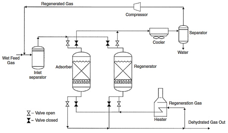
This is achieved by passing through cold gas. After heating, the same gas can be used for regeneration. In these conditions, four beds are needed in practice in cyclic operation to dry the gas on a continuous Adsorbents are normally unsuitable for continuous circulation due to mechanical problems and also due to the risks of attrition.x basis: two beds operating simultaneously in adsorption or gas drying cycle, one bed in the cooling cycle, and one bed in the regeneration cycle. In the simplest case (as shown in Figure 7), one bed operates in adsorption, while the second operates in desorption, and both beds are switched periodically.
In the gas drying cycle, the wet inlet gas first passes through an inlet separator where free liquids, entrained mist, and solid particles are removed. This is a very important part of the system because free liquids can cause the adsorbent materials to break down. This leads to higher pressure drop and channeling, reducing the overall performance of the unit. If the adsorption unit is downstream from an amine unit, glycol unit, or compressors, a filter separator is required.
In addition to the use of an inlet separator to maximize water droplet removal, a guard layer (equal to about 10-20 % of bed volume) of specialized, water-stable adsorbent can be added on top of the main adsorbent bed. This water stability can be imparted using tempering (i. e., heating to high temperatures over a long time), however, this process reduces water adsorption capacity greatly.
In the adsorption cycle, the wet inlet gas flows usually downward through the tower. The adsorbable components are adsorbed at rates dependent on their chemical nature, the size of their molecules, and the size of the pores in the solid material. The water molecules are adsorbed first in the top layers of the desiccant bed. Dry hydrocarbon gases are adsorbed throughout the bed. As the upper layers of desiccant become saturated with water, the water in the wet gas stream begins displacing the previously adsorbed hydrocarbons in the lower desiccant layers.
Liquid hydrocarbons will also be absorbed and will fill pore spaces that would otherwise be available for water molecules. For each component in the inlet gas stream, there will be a section of bed depth, from top to bottom, where the desiccant is saturated with that component and where the desiccant below is just starting to adsorb that component. The depth of bed from saturation to initial adsorption is known as the mass transfer zone (MTZ). This is simply a zone or section of the bed where a component is transferring its mass from the gas stream to the surface of the desiccant. In the mass transfer zone, the water content of the gas is reduced from saturation to less than 1 ppm. As the flow of gas continues, the mass transfer zone moves downward through the bed and water displaces the previously adsorbed gases until finally the entire bed is saturated with water vapor. When the leading edge of the MTZ reaches the end of the bed, breakthrough occurs. If the entire bed becomes completely saturated with water vapor, the outlet gas is just as wet as the inlet gas. Obviously, the towers must be switched from the adsorption cycle to the regeneration cycle (heating and cooling) before the desiccant bed is completely saturated with water.
It will be interesting: Bunkering Risk on Liquefied Natural Gas Ships Assessment and Safety Zones
At any given time, at least one of the towers will be adsorbing while the other towers will be in the process of being heated or cooled to regenerate the desiccant. When a tower is switched to the regeneration cycle, some wet gas (i. e., the inlet gas downstream of the inlet gas separator) is heated to temperatures of 450 to 600 °F in the high-temperature heater and routed to the tower to remove the previously adsorbed water. As the temperature within the tower is increased, the water captured within the pores of the desiccant turns to steam and is absorbed by the natural gas.
This gas leaves the top of the tower and is cooled by the regeneration gas cooler. When the gas is cooled the saturation level of water vapor is lowered significantly and water is condensed. The water is separated in the regeneration gas separator and the cool, saturated regeneration gas is recycled to be dehydrated. This can be done by operating the dehydration tower at a lower pressure than the tower being regenerated or by recompressing the regeneration gas. Once the bed has been “dried” in this manner, it is necessary to flow cool gas through the tower to return it to normal operating temperatures (about 100 to 120 °F) before placing it back in service to dehydrate gas. The cooling gas could either be wet gas or gas that has already been dehydrated. If wet gas is used, it must be dehydrated after being used as cooling gas, where a hot tower will not sufficiently dehydrate the gas.
The switching of beds is controlled by a time controller that performs switching operations at specified times in the cycle. The length of the different phases can vary considerably. Longer cycle times will require larger beds and additional capital investment, but will increase the bed life. A typical two-bed cycle might have an 8-hour adsorption period with 6 hours of heating and 2 hours of cooling for regeneration. The 16-hour adsorption time for an adsorption unit with three beds, two beds in adsorption and one bed in regeneration, makes also a full cycle time of 24 hours, which gives a good 3-year guarantee.
Internal or external insulation for the adsorbers may be used. The main purpose of internal insulation is to reduce the total regeneration gas requirements and costs (invest cost, however, is higher). Internal insulation eliminates the need to heat and cool the steel walls of the adsorber vessel. Normally, a castable refactory lining is used for internal insulation. The refractory must be applied and cured properly to prevent liner cracks. Liner cracks will permit some of the wet gas to bypass the desiccant bed.
Only a small amount of wet, bypassed gas is needed to cause freeze ups in cryogenic plants. Ledges installed every few feet along the vessel wall can help eliminate this problem.
Design Considerations
The following considerations are a good approximation for estimation of the solid desiccant dehydration behavior. This information serves only as a basis for performing preliminary design calculations based on a given cycle length, number of vessels and their configuration, and a given desiccant. Therefore, it is highly recommended to refer to desiccant vendors for designing a solid desiccant dehydration unit, as the useful capacity of a desiccant is highly dependent on its aging behavior. To take aging into account, experience is very important and no published correlations exist as every desiccant vendor regards that as their own intellectual property and know how. To use only literature data will result in either uneconomical units or potentially nonworking units.
Allowable Gas Velocity
Generally, as the gas velocity during the drying cycle decreases, the ability of the desiccant to dehydrate the gas increases (there is certainly an upper limit on space velocity due to adsorption kinetics, but more often other considerations such as fluidization of the bed restrict upper velocities).
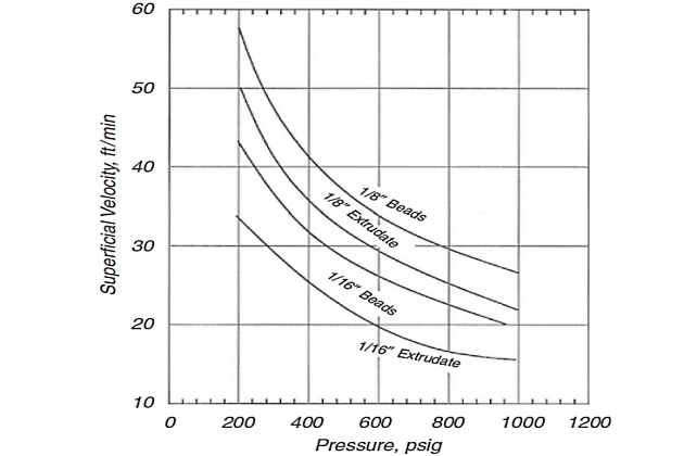
At lower actual velocities, drier effluent gases will be obtained. Consequently, it would seem desirable to operate at minimum velocities to fully use the desiccant. However, low velocities require towers with large crosssectional areas to handle a given gas flow and allow the wet gas to channel through the desiccant bed with incomplete dehydration. In selecting the design velocity, therefore, a compromise must be made between the tower diameter and the maximum use of the desiccant. Figure 8 shows a maximum allowable superficial gas velocity for mole sieve materials. Smaller velocities may be required due to pressure drop considerations.
An alternative method for determining superficial gas velocity in a molecular sieve bed is using the Ergun equation, which relates ∆P to VSG, µ, ρ, and desiccant size, as follows:
where:
- ∆P/L – is pressure drop per length of bed, psi/ft;
- µ – is gas viscosity, cP;
- ρG – is gas density, lb/ft3;
- and VSG – is superficial gas velocity, ft/min. Constants for Equation 9 are given in Table 1 for mole sieve materials.
An important observation from Equation 9 is that the higher the gas superficial velocity, the greater the pressure drop across the bed. The design gas velocity is therefore a trade-off between the maximum gas velocity and the acceptable pressure drop.
| Table 1. Parameters Used in Equation 9 | ||
|---|---|---|
| Particle type | Coefficients | |
| B | C | |
| 1/8-in. beads | 0,0560 | 0,0000889 |
| 1/8-in. extrudate | 0,0722 | 0,000124 |
| 1/16-in. beads | 0,152 | 0,000136 |
| 1/16-in. extrudate | 0,238 | 0,000210 |
The design pressure drop across the entire bed should be about 5 psi; values higher than approximately 8 psi are not recommended. Most designs are based on a ∆P/L of about 0,31-0,44 psi/ft and typical superficial gas velocities of 30-60 ft/min.
Bed Length to Diameter Ratio
Once the superficial gas velocity is determined, then the diameter and length of the bed can be calculated from geometry of the adsorber. In its simplest form, an adsorber is normally a cylindrical tower filled with a solid desiccant. The depth of the desiccant may vary from a few feet to 30 ft or more. The minimum bed internal diameter for a specified superficial gas velocity is given by the following equation:
where:
- D – is bed diameter, ft;
- QG – is gas flow rate, MMscfd;
- T – is inlet gas temperature, °R;
- P – is inlet gas pressure, psia;
- Z – is compressibility factor;
- and VSG – is superficial gas velocity, ft/min.
Also, the bed length, LB, can be determined by the following equation:
where:
- LB – is bed length, ft;
- W – is weight of water adsorbed, lb per cycle;
- ρb – is bulk density of desiccant, lb/ft3;
- and X – is maximum desiccant useful capacity, lb water/100 lb desiccant.
A bed length to diameter ratio of higher than 2,5 is desirable. A ratio as low as 1:1 is sometimes used; however, poor gas dehydration, caused by nonuniform flow, channeling and an inadequate contact time between the wet gas and the desiccant sometimes result.
Desiccant Capacity
The maximum desiccant useful capacity can be calculated as Equation 12. However, this is an empirical equation that does not accurately encompass all the factors affecting the mass transfer zone. It is reasonable only within a limited range of pressure, temperature, aging mechanisms, compositions, and so on.
where:
- X – is desiccant useful capacity, lb water per 100-lb desiccant;
- XS – is dynamic capacity at saturation, lb water per 100-lb desiccant;
- LZ – is MTZ length, ft;
- and LB – is bed length, ft.
The numerical value of (0,45) in Equation 12 is an average number based on test. It is a function of MTZ length but only varies from 0,40 to 0,52 in a wide range of applications. The value used is the mode of the distribution curve for most services. The dynamic capacity “XS” must reflect desiccant aging and other such factors. It is the effective capacity of the desiccant for water behind the adsorption zone. Because desiccant degrades in service, the value used must reflect a capacity at some future time to optimize desiccant replacement cost. Figure 9 (a) may be used to predict “XS” in Equation 12 as a function of relative saturation.
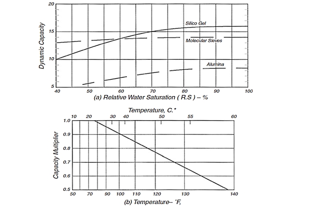
Remember that relative gas saturation is fixed by the last pressure and temperature at which liquid water was present – the last separator producing any water or the reservoir. If any water is drained off the inlet scrubber, the inlet gas is saturated. If not, the saturated water content at the previous contact divided by that at the dehydrator gives the relative saturation (RS) value as a fraction.
The values in Figure 9 (a) are lower than the theoretical numbers published for air. They are for natural gas and reflect the competition of the hydrocarbons for adsorption surface and expected dynamic saturation after a short-time use in an actual plant with normal degradation only.
Read also: Recommended methods for calculating LNG
For gels and aluminas, the values in Figure 9 (a) must be corrected for temperature. No temperature correction is needed for molecular sieves in the temperature range shown. The value from Figure 9 (b) is multiplied by that in Figure 9 (a) to obtain the “XS” for use in Equation 12. The “X” obtained from Equation 12 will be the useful capacity of virgin, activated desiccant. This is greater than the useful capacity after degradation.
In effect, Equation 12 simply corrects for that amount of bed unused because of zone length.
MTZ Length
The MTZ length, LMTZ, depends on gas composition, flow rate, RS of the water in the gas, and the loading capability of the desiccant. Pressure has only a small effect, particularly above 300 psia. For silica gel, the MTZ length may be estimated from the following equation.
where:
- LMTZ – is MTZ length, inch;
- mw – is water loading, lb/(hr.ft2);
- VSG – is gas superficial velocity, ft/min;
- RS – is percentage relative saturation of inlet gas.
The values of “LMTZ” from Equation 13 are those quoted from Simpson and Cummings for air drying. The values, however, are useful for natural gas drying. For alumina and molecular sieves, the zone length determined using Equation 13 is multiplied by 0,8 and 0,6, respectively. Shorter zones are obtained with these materials because they have less capacity for hydrocarbon.
The relevant equation for calculation of the water loading (mw) can be written as follows:
where:
- QG – is gas flow rate, MMscfd;
- D – is bed diameter, ft;
- and W – is water content of gas, lb/MMscf. This is the water loading on a mass basis.
Equation 14 is merely a conversion from water content per standard volume divided by bed cross-sectional area.
Breakthrough Time
The breakthrough time for the water zone formed, tb in hours, can be estimated as follows:
For a given set of gas flow conditions, water loading, cycle length, and tower configuration, one can size the desiccant bed. However, as stated earlier, desiccant vendors typically perform these kinds of calculations and will even guarantee. This is important today as design is becoming more effective and incorrect assumptions might lead to misguided process choice.
Operational Problems
Operational problems that may occur because of poor design, operation, and maintenance in a solid desiccant unit are described in this section.
Bed Contamination
The most frequent cause is incomplete removal of contaminants in the inlet gas separator. Also, if the regeneration gas leaving the separator is commingled with the feed gas to the dehydrators, then a separator malfunction can dump liquid hydrocarbons and water onto the desiccant. Regeneration separators should usually be equipped with filtration levels similar to the inlet gas to prevent recontamination.
High Dew Point
High dew point is one of the two common problems that can cause operating trouble. Possible causes include the following.
- “Wet” inlet gas bypasses the dehydrator through cracks in the internal insulation. Cracks in a liner or in sprayed-on insulation can be detected by “hot spots” and peeling paint on the outer shell. Other symptoms are fast water breakthrough and an unusually rapid rise in the effluent gas temperature during regeneration.
- Leaking valves also permit wet gas to bypass the dehydrators. Even a slight leak of hot gas usually produces a detectable temperature rise in what should be the cold side of the valve. Ultrasonic translators are also useful.
- Incomplete desiccant regeneration will lead to a sudden loss in adsorption capacity and a significantly premature breakthrough. To be sure to well regenerate the adsorbents the inlet and outlet temperatures of the adsorber in regeneration should be analyzed. At the end of the heating step the outlet temperature should be almost constant during a certain time (30 minutes to 2 hours) depending on the design of the adsorber, and the temperature difference between inlet and outlet should not be more than 59-68 °F depending on the quality of the heat insulation.
- Excessive water content in the wet feed gas due to increased flow rate, higher temperatures, and lower pressure. It is very important to respect the inlet temperature (feed temperature) of the adsorbers in case of saturated gas. Small variations in temperature will lead to significant increases in the water content.
Premature Breakthrough
Satisfactory dew points are observed at the beginning but not for the entire duration of the drying cycle. Desiccant capacity should decrease with use but should stabilize at 55-70 % of the initial capacity.
However, premature symptoms of “old age” are caused by an unrecognized increase in inlet water loading, an increase in heavy hydrocarbons (C4+) in feed gas, methanol vapor in feed, desiccant contamination, or incomplete regeneration.
Hydrothermal Damaging
Heating up the adsorber without using a heating ramp or an intermediate heating step leads to a strong temperature difference in the vessel. At the bottom, the molecular sieve will be very hot and will desorb rapidly the adsorbed water while the layers at the top of the adsorber will be still at adsorption temperature. The water desorbed in the bottom layer will condense in the top layer. This phenomenon is called refluxing. The heating going on will heat up the liquid water and boil the molecular sieves in liquid water. Hydrothermal damaging will appear in consequence, which is different depending on the type of molecular sieve.
It will be interesting: Personal protection of crew on Gas Carriers
In order to prevent hydrothermal damaging of molecular sieves it is not only important to choose the right formulation of the molecular sieve (binder and zeolite) but the operating conditions; the regeneration conditions should be determined carefully. In fact, the higher the regeneration temperature and the higher the amount of liquid water present on the sieves, the heavier the damaging of the molecular sieves. In an industrial unit it is also important to limit the quantity of water appearing in liquid phase (condensing water due to oversaturation of the gas phase), as this decreases the temperature where hydrothermal destruction may occur with the water acting as a stabilizer for intermediates formed by dissolution of the zeolites.
Liquid Carryover
Liquid (particularly amines) carryover in the molecular sieve bed has a negative impact on the drying process (i. e., poor gas flow distribution due to cake or fines formation as a consequence of chemical attack causing an increase of the pressure drop and a decrease of adsorption time). In order to reduce the liquid carryover in adsorbers, separators must be modified to improve their efficiency. The regeneration procedure should also be changed so as to have a moderate temperature increase to avoid water recondensation. Although on-site mechanical changes of the drying unit can improve the performance, however, the right corrective action can be found by using a more resistant molecular sieve, i. e., SRA. The SRA adsorbent offers a better mechanical resistance than the regular one to severe operating conditions simulating the thermal regeneration step of a natural gas purification unit.
Bottom Support
Sometimes operators have problems with the support grid and leakage of molecular sieves through the support grid. As a result, they have to replace the whole bed. Important point here is the good mechanical design of the support bed, putting three wire mesh on the support grid (4, 10, 20 mesh) and installing the correct quantity and size of ceramic balls.

- Acikgoz, M., Franca, F., and Lahey Jr, R. T., An experimental study of three-phase flow regimes. Int. J. Multiphase Flow 18(3), 327-336 (1992).
- Adewmi, M. A., and Bukacek, R. F., Two-phase pressure drop in horizontal pipelines. J. Pipelines 5, 1-14 (1985).
- Amdal, J., et al., “Handbook of Multiphase Metering.” Produced for The Norwegian Society for Oil and Gas Measurement, Norway (2001).
- Ansari, A. M., Sylvester, A. D., Sarica, C., Shoham, O., and Brill, J. P., A comprehensive mechanistic model for upward two-phase flow in wellbores. SPE Prod. Facilit. J. 143-152 (May 1994).
- API, “Computational Pipeline Monitoring”. API Publication 1130, 17, American Petroleum Institute, TX (1995a).
- API, “Evaluation Methodology for Software Based Leak Detection Systems”. API Publication 1155, 93, American Petroleum Institute, TX (1995b).
- API RP 14E, “Recommended Practice for Design and Installation of Offshore Production Platform Piping Systems”, 5th Ed., p. 23.
- Asante, B., “Two-Phase Flow: Accounting for the Presence of Liquids in Gas Pipeline Simulation”. Paper presented at 34th PSIG Annual Meeting, Portland, Oregon (Oct. 23–25, 2002).
- AsphWax’s Flow Assurance course, “Fluid Characterization for Flow Assurance”. AsphWax Inc., Stafford, TX (2003).
- Ayala, F. L., and Adewumi, M. A., Low-liquid loading multiphase flow in natural gas pipelines. ASME J. of Energy Res. Technol. 125, 284-293 (2003).
- Baillie, C., and Wichert, E., Chart gives hydrate formation temperature for natural gas. Oil Gas J. 85(4), 37-39 (1987).
- Baker, O., Design of pipelines for simultaneous flow of oil and gas. Oil Gas J. 53, 185 (1954).
- Banerjee, S., “Basic Equations”. Lecture presented at the Short Course on Modeling of Two-Phase Flow Systems, ETH Zurich, Switzerland (March 17-21, 1986).
- Barnea, D., A unified model for prediction flow pattern transitions for the whole range of pipe inclinations. Int. J. Multiphase Flow 13(1), 1-12 (1987).
- Barnea, D., and Taitel, Y., Stratified three-phase flow in pipes: Stability and transition. Chem. Eng. Comm. 141–142, 443-460 (1996).
- Battara, V., Gentilini, M., and Giacchetta, G., Condensate-line correlations for calculating holdup, friction compared to field data. Oil Gas J. 30, 148–52 (1985).
- Bay, Y., “Pipelines and Risers”, Vol. 5. Elsevier Ocean Engineering Book Series (2001).
- Beggs, H. D., and Brill, J. P., “A Study of Two-Phase Flow in Inclined Pipes”. JPT, 607-17; Trans., AIME, 255 (May 1973).
- Bendiksen, K., Brandt, I., Jacobsen, K. A., and Pauchon, C., “Dynamic Simulation of Multiphase Transportation Systems”. Multiphase Technology and Consequence for Field Development Forum, Stavanger, Norway (1987).
- Bendiksen, K., Malnes, D., Moe, R., and Nuland, S., The dynamic two-fluid model OLGA: Theory and application. SPE Prod. Eng. 6, 171-180 (1991).
- Bertola, V., and Cafaro, E., “Statistical Characterization of Subregimes in Horizontal Intermittent Gas/Liquid Flow”. Proc. the 4th International Conference on Multiphase Flow, New Orleans, LA (2001).
- Bjune, B., Moe, H., and Dalsmo, M., Upstream control and optimization increases return on investment. World Oil 223, 9 (2002).
- Black, P. S., Daniels, L. C., Hoyle, N. C., and Jepson, W. P., Studying transient multiphase flow using the pipeline analysis code (PLAC). ASME J. Energy Res. Technol. 112, 25-29 (1990).
- Bloys, B., Lacey, C., and Lynch, P., “Laboratory Testing and Field Trial of a New Kinetic Hydrate Inhibitor”. Proc. 27th Annual Offshore Technology Conference, OTC 7772, PP. 691-700, Houston, TX (1995).
- Bonizzi, M., and Issa, R. I., On the simulation of three-phase slug flow in nearly horizontal pipes using the multi-fluid model. Int. J. Multiphase Flow 29, 1719-1747 (2003).
- Boriyantoro, N. H., and Adewumi, M. A., “An Integrated Single-Phase/Two-Phase Flow Hydrodynamic Model for Predicting the Fluid Flow Behavior of Gas Condensate Pipelines”. Paper presented at 26th PSIG Annual Meeting, San Diego, CA (1994).
- Brauner, N., and Maron, M. D., Flow pattern transitions in two-phase liquid-liquid flow in horizontal tubes, Int. J. Multiphase Flow 18, 123-140 (1992).
- Brauner, N., The prediction of dispersed flows boundaries in liquid-liquid and gas-liquid systems, Int. J. Multiphase Flow 27, 885-910 (2001).
- Brill, J. P., and Beggs, H. D., “Two-Phase Flow in Pipes”, 6th Ed. Tulsa University Press, Tulsa, OK (1991).
- Bufton, S. A., Ultra Deepwater will require less conservative flow assurance approaches. Oil Gas J. 101(18), 66-77 (2003).
- Campbell, J. M., “Gas Conditioning and Processing”, 3rd Ed. Campbell Petroleum Series, Norman, OK (1992).
- Carroll, J. J., “Natural Gas Hydrates: A Guide for Engineers”. Gulf Professional Publishing, Amsterdam, The Netherlands (2003).
- Carroll, J. J., “An Examination of the Prediction of Hydrate Formation Conditions in Sour Natural Gas”. Paper presented at the GPA Europe Spring Meeting, Dublin, Ireland (May 19-21, 2004).
- Carson, D. B., and Katz, D. L., Natural gas hydrates. Petroleum Trans. AIME 146, 150-158 (1942).
- Chen, C. J., Woo, H. J., and Robinson, D. B., “The Solubility of Methanol or Glycol in Water-Hydrocarbon Systems”. GPA Research Report RR-117, Gas Processors Association, OK (March 1988).
- Chen, X., and Guo, L., Flow patterns and pressure drop in oil-air-water three-phase flow through helically coiled tubes. Int. J. Multiphase Flow 25, 1053-1072 (1999).
- Cheremisinoff, N. P., “Encyclopedia of Fluid Mechanics”, Vol. 3. Gulf Professional Publishing, Houston, TX (1986).
- Chisholm, D., and Sutherland, L. A., “Prediction of Pressure Gradient in Pipeline Systems during Two-Phase Flow”. Paper presented at Symposium on Fluid Mechanics and Measurements in Two-Phase Flow Systems, Leeds (Sept. 1969).
- Cindric, D. T., Gandhi, S. L., and Williams, R. A., “Designing Piping Systems for Two-Phase Flow”. Chem. Eng. Progress, 51-59 (March 1987).
- Collier, J. G., and Thome, J. R., “Convective Boiling and Condensation”, 3rd Ed. Clarendon Press, Oxford, UK (1996).
- Colson, R., and Moriber, N. J., Corrosion control. Civil Eng. 67(3), 58-59 (1997).
- Copp, D. L., “Gas Transmission and Distribution”. Walter King Ltd., London (1970).
- Courbot, A., “Prevention of Severe Slugging in the Dunbar 16 Multiphase Pipelines”. Paper presented at the Offshore Technology Conference, Houston, TX (May 1996).
- Covington, K. C., Collie, J. T., and Behrens, S. D., “Selection of Hydrate Suppression Methods for Gas Streams”. Paper presented at the 78th GPA Annual Convention, Nashville, TN (1999).
- Cranswick, D., “Brief Overview of Gulf of Mexico OCS Oil and Gas Pipelines: Installation, Potential Impacts, and Mitigation Measures”. U. S. Department of the Interior, Minerals Management Service, Gulf of Mexico OCS Region, New Orleans, LA (2001).
- Dhl, E., et al., “Handbook of Water Fraction Metering”, Rev. 1. Norwegian Society for Oil and Gas Measurements, Norway (June 2001).
- Decarre, S., and Fabre, J., Etude Sur La Prediction De l’Inversion De Phase. Revue De l’Institut Francais Du Petrole 52, 415-424 (1997).
- De Henau, V., and Raithby, G. D., A transient two-fluid model for the simulation of slug flow in pipelines. Int. J. Multiphase Flow 21, 335–349 (1995).
- Dukler, A. E., “Gas-Liquid Flow in Pipelines Research Results”. American Gas Assn. Project NX-28 (1969).
- Dukler, A. E., and Hubbard, M. G., “The Characterization of Flow Regimes for Horizontal Two-Phase Flow”. Proc. Heat Transfer and Fluid Mechanics Institute, 1, 100-121, Stanford University Press, Stanford, CA (1966).
- Eaton, B. A., et al., The prediction of flow pattern, liquid holdup and pressure losses occurring during continuous two-phase flow in horizontal pipelines. J. Petro. Technol. 240, 815-28 (1967).
- Edmonds, B., et al., “A Practical Model for the Effect of Salinity on Gas Hydrate Formation”. European Production Operations Conference and Exhibition, Norway (April 1996).
- Edmonds, B., Moorwood, R. A. S., and Szczepanski, R., “Hydrate Update”. GPA Spring Meeting, Darlington (May 1998).
- Esteban, A., Hernandez, V., and Lunsford, K., “Exploit the Benefits of Methanol”. Paper presented at the 79th GPA Annual Convention, Atlanta, GA (2000).
- Fabre, J., et al., Severe slugging in pipeline/riser systems. SPE Prod. Eng. 5(3), 299-305 (1990).
- Faille, I., and Heintze, E., “Rough Finite Volume Schemes for Modeling Two-Phase Flow in a Pipeline”. In Proceeding of the CEA.EDF.INRIA Course, INRIA Rocquencourt, France (1996).
- Fidel-Dufour, A., and Herri, J. S., “Formation and Dissociation of Hydrate Plugs in a Water in Oil Emulsion”. Paper presented at the 4th International Conference on Gas Hydrates, Yokohama, Japan (2002).
- Frostman, L. M., “Anti-aggolomerant Hydrate Inhibitors for Prevention of Hydrate Plugs in Deepwater Systems”. Paper presented at the SPE Annual Technical Conference and Exhibition, Dallas, TX (Oct. 1-4, 2000).
- Frostman, L. M., et al., “Low Dosage Hydrate Inhibitors (LDHIs): Reducing Total Cost of Operations in Existing Systems and Designing for the Future”. Paper presented at the SPE International Symposium on Oilfield Chemicals, Houston, TX (Feb. 5-7, 2003).
- Frostman, L. M., “Low Dosage Hydrate Inhibitor (LDHI) Experience in Deepwater”. Paper presented at the Deep Offshore Technology Conference, Marseille, France (Nov. 19-21, 2003).
- Fuchs, P., “The Pressure Limit for Terrain Slugging”. Proceeding of the 3rd BHRA International Conference on Multiphase Flow, Hague, The Netherlands (May 1987).
- Furlow, W., “Suppression System Stabilizes Long Pipeline-Riser Liquid Flows”. Offshore, Deepwater D&P, 48 + 166 (Oct., 2000).
- Giot, M., “Three-Phase Flow”, Chap. 7.2. McGraw-Hill, New York (1982).
- Goulter, D., and Bardon, M., Revised equation improves flowing gas temperature prediction. Oil Gas J. 26, 107-108 (1979).
- Govier, G. W., and Aziz, K., “The Flow of Complex Mixtures in Pipes”. Van Nostrand Reinhold Co., Krieger, New York (1972).
- GPSA Engineering Data Book, 11th Ed. Gas Processors Suppliers Association, Tulsa, OK (1998).
- Gregory, G. A., and Aziz, K., Design of pipelines for multiphase gas-condensate flow. J. Can. Petr. Technol. 28-33 (1975).
- Griffith, P., and Wallis, G. B., Two-phase slug flow. J. Heat Transfer Trans. ASME. 82, 307-320 (1961).
- Haandrikman, G., Seelen, R., Henkes, R., and Vreenegoor, R., “Slug Control in Flowline/Riser Systems”. Paper presented at the 2nd International Conference on Latest Advance in Offshore Processing, Aberdeen, UK (Nov. 9-10, 1999).
- Hall, A. R. W., “Flow Patterns in Three-Phase Flows of Oil, Water, and Gas”. Paper presented at the 8th BHRG International Conference on Multiphase Production, Cannes, France (1997).
- Hammerschmidt, E. G., Formation of gas hydrates in natural gas transmission lines. Ind. Eng. Chem. 26, 851-855 (1934).
- Hart, J., and Hamersma P. J. Correlations predicting frictional pressure drop and liquid holdup during horizontal gas-liquid pipe flow with small liquid holdup. Int. J. Multiphase Flow 15(6), 974-964 (1989).
- Hartt, W. H., and Chu, W., New methods for CP design offered. Oil Gas J. 102(36), 64-70 (2004).
- Hasan, A. R., Void fraction in bubbly and slug flow in downward two-phase flow in vertical and inclined wellbores, SPE Prod. Facil. 10(3), 172–176 (1995).
- Hasan, A. R., and Kabir, C. S., “Predicting Multiphase Flow Behavior in a Deviated Well”. Paper presented at the 61st SPE Annual Technical Conference and Exhibition, New Orleans, LA (1986).
- Hasan, A. R., and Kabir, C. S., Gas void fraction in two-phase up-flow in vertical and inclined annuli. Int. J. Multiphase Flow 18(2), 279-293 (1992).
- Hasan, A. R., and Kabir, C. S., Simplified model for oil/water flow in vertical and deviated wellbores. SPE Prod. Facil. 14(1), 56-62 (1999).
- Hasan, A. R., and Kabir, C. S., “Fluid and Heat Transfers in Wellbores”. Society of Petroleum Engineers (SPE) Publications, Richardson, TX (2002).
- Havre, K., and Dalsmo, M., “Active Feedback Control as the Solution to Severe Slugging”. Paper presented at the SPE Annual Technical Conference and Exhibition, New Orleans, LA (Oct. 3, 2001).
- Havre, K., Stornes, K., and Stray, H., “Taming Slug Flow in Pipelines”. ABB Review No. 4, 55-63, ABB Corporate Research AS, Norway (2000).
- Hedne, P., and Linga, H., “Suppression of Terrain Slugging with Automatic and Manual Riser Chocking”. Advances in Gas-Liquid Flows, 453-469 (1990).
- Hein, M., “HP41 Pipeline Hydraulics and Heat Transfer Programs.” PennWell Publishing Company, Tulsa, OK (1984).
- Henriot, V., Courbot, A., Heintze, E., and Moyeux, L., “Simulation of Process to Control Severe Slugging: Application to the Dunbar Pipeline”. Paper presented at the SPE Annual Conference and Exhibition, Houston, TX (1999).
- Hewitt, G. F., and Roberts, D. N., “Studies of Two-Phase Flow Patterns by Simultaneous X-ray and Flash Photography”. AERE-M 2159, HMSO (1969).
- Hill, T. H., Gas injection at riser base solves slugging, flow problems. Oil Gas J. 88(9), 88-92 (1990).
- Hill, T. J., “Gas-Liquid Challenges in Oil and Gas Production”. Proceeding of ASME Fluids Engineering Division Summer Meeting, Vancouver, BC, Canada (June 22-26, 1997).
- Holt, A. J., Azzopardi, B. J., and Biddulph, M. W., “The Effect of Density Ratio on Two-Phase Frictional Pressure Drop”. Paper presented at the 1st International Symposium on Two-Phase Flow Modeling and Experimentation, Rome, Italy (Oct. 9-11, 1995).
- Holt, A. J., Azzopardi, B. J., and Biddulph, M. W., Calculation of two-phase pressure drop for vertical up flow in narrow passages by means of a flow pattern specific models. Trans. IChemE 77(Part A), 7-15 (1999).
- Hunt, A., Fluid properties determine flow line blockage potential. Oil Gas J. 94(29), 62–66 (1996).
- IFE, “Mitigating Internal Corrosion in Carbon Steel Pipelines”. Institute of Energy Technology News, Norway (April 2000).
- Jansen, F. E., Shoham, O., and Taitel, Y., The elimination of severe slug-ging, experiments and modeling. Int. J. Multiphase Flow 22(6), 1055-1072 (1996).
- Johal, K. S., et al., “An Alternative Economic Method to Riser Base Gas Lift for Deepwater Subsea Oil/Gas Field Developments”. Proceeding of the Offshore Europe Conference, 487-492, Aberdeen, Scotland (9-12 Sept., 1997).
- Jolly, W. D., Morrow, T. B., O’Brien, J. F., Spence, H. F., and Svedeman, S. J., “New Methods for Rapid Leak Detection in Offshore Pipelines”. Final Report, SWRI Project No. 04-4558, SWRI (April 1992).
- Jones, O. C., and Zuber, N., The interrelation between void fraction fluctuations and flow patterns in two-phase flow Int. J. Multiphase Flow. 2, 273-306 (1975).
- Sloan, E. D., Jr., “Hydrate Engineering”. SPE Monograph, 21, Society of Petroleum Engineers (SPE) Publications, Richardson, TX (2000).
- Smart, J., A method for calculating the corrosion allowance for deepwater pipelines and risers. J. Pipeline Integrity 73 (2001).
- Soldati, A., Paglianti, A., and Giona, M., Identification of two-phase flow regimes via diffusional analysis of experimental time series. Exp. Fluids 21, 151–160 (1996).
- Son, V. K., and Wallace, C., “Reclamation/Regeneration of Glycols Used for Hydrate Inhibition”. Paper presented at the 12th Annual Deep Offshore Technology Conference and Exhibition, New Orleans, LA (Nov. 7-9, 2000).
- Sotberg, T., and Bruschi, R., “Future Pipeline Design Philosophy-Framework”. Paper presented at the 11th International Conference on Offshore Mechanics and Arctic Engineering, Calgary, AB, Canada (1992).
- Storkaas, E., Alstad, V., and Skogestad, S., “Stabilization of Desired Flow Regimes in Pipelines”. Paper presented at the AIChE Annual Meeting, Reno, NV (2001).
- Strommen, R. D., Horn, H., and Wold, K. R., New technique monitors pipeline corrosion, cracking. Oil Gas J. 91(52), 88–92 (1993).
- Taitel, Y., Stability of severe slugging. Int. J. Multiphase Flow 12(2), 203–217 (1986).
- Taitel, Y., “Flow Pattern Transition in Two-Phase Flow.” Paper presented at the 9th International Heat Transfer Conference, Jerusalem (1990).
- Taitel, Y., Barnea, D., and Brill, J. P., Stratified three-phase flow in pipes. Int. J. Multiphase Flow. 21(1), 53-60 (1995).
- Taitel, Y., Barnea, D., and Dukler, A. E., Modeling flow pattern transitions for steady upward gas-liquid flow in vertical tubes. AIChE J. 26(3), 345–354 (1980).
- Taitel, Y., and Dukler, A. E., A model for predicting flow regime transitions in horizontal and near horizontal gas-liquid flow. AIChE J. 22(1), 47 (1976).
- Taitel, Y., Shoham, O., and Brill, J. P., Simplified transient solution and simulation of two-phase flow in pipelines. Chem. Eng. Sci. 44(6), 1353–1359 (1989).
- Tek, M. R., Multiphase flow of water, oil, and natural gas through vertical flow strings. Journal of Petroleum Technology (JPT), 1029–1036 (1961).
- Tin, V., “Severe Slugging in Flexible Risers”. Proceeding of the 5th BHRG International Conference on Multiphase Production, 507–525, Cannes, France (1991).
- Tiratsoo, J. N. H., “Pipeline Pigging Technology”, 2nd Ed. Gulf Professional Publishing, Houston, TX (1992).
- Towler, B. F., and Mokhatab, S., Quickly estimate hydrate formation conditions in natural gases. Hydrocarb. Proc. 84(4), 61–62 (2005).
- Trekell, R. E., and Campbell, J.M., “Prediction of the Behavior of Hydro-carbon Clathrate Solutions”. Proceedings of the 151st Meeting of American Chemical Society, Petroleum Chemistry Division, 61, Pittsburgh, PA (March 1966).
- Uhl, A. E., “Steady Flow in Gas Pipelines”. IGT Report No. 10, American Gas Association (AGA), New York, (1965).
- Uhlig, H. H., and Revie, R. W., “Corrosion and Corrosion Control”, 3rd Ed. Wiley, New York (1985).
- Ullah, M. R., A comprehensive assessment of the performance of dry-gas methods for predicting the occurrence of wet-gas flow conditions. J. Pipelines 6 (1987).
- Van Hout, R., Shemer, L., and Barnea, D., Spatial distribution of void fraction within the liquid slug and some other related slug parameters. Int. J. Multiphase Flow 18, 831–845 (1992).
- Varughese, K., In-situ pipeline rehabilitation techniques, equipment improved. Oil Gas J. 91(25), 54–57 (1993).
- Verley, R., et al., “Wall Thickness Design for High Pressure Offshore Gas Pipelines”. Paper presented at the 13th International Conference on Offshore Mechanics and Arctic Engineering, Houston, TX (Feb. 27–March 3, 1994).
- Wallis, G. B., “One Dimensional Two-Phase Flow”. McGraw-Hill, New York (1969).
- Wilkens, R. J., “Prediction of the Flow Regime Transitions in High Pressure, Large Diameter, Inclined Multiphase Pipelines”. Ph.D. Thesis, Ohio University, Athens, OH (1997).
- Wilkens, R. J., Flow assurance. In “Fluid Flow Handbook” (J. Saleh, ed.), Chapter 29. McGraw-Hill, New York (2002).
- Xiao, J. J., Shoham, O., and Brill, J. P., “A Comprehensive Mechanistic Model for Two-Phase Flow in Pipelines”. Paper presented at the 65th SPE Annual Technical Conference and Exhibition, New Orleans, LA (Sept. 23–26, 1990).
- Xiao, J. J., and Shoup, G., Sizing wet-gas pipelines and slug catchers with steady-state multiphase flow simulations. ASME J. Energy Res. Technol. 120, 106–110 (1998).
- Yeung, H. C., and Lima, P. C. R., Modeling of pig assisted production methods. ASME J. Energy Res. Technol. 124, 8–13 (2002).
- Yocum, B. T., “Offshore Riser Slug Flow Avoidance: Mathematical Model for Design and Optimization”. Paper presented at the SPE London Meeting, London, UK (1973).
- Zhang, H.-Q., Wang, Q., Sarica, C., and Brill, J. P., Unified model for gas-liquid pipe flow via slug dynamics. 1. Model development. ASME J. Energy Res. Technol. 125(4), 266–273 (2003).
- Zuo, J. Y., and Zhang, D. D., “Gas Hydrate Formation in Aqueous Solutions Containing Methanol and Electrolytes”. Proceedings of the Laurance Reid Gas Conditioning Conference, 191–198, Norman, OK (Feb. 21–24, 1999).
Did you find mistake? Highlight and press CTRL+Enter