Modern gas processing facilities are complex, integrated operations requiring precise and reliable management to ensure safety, efficiency, and compliance. The core of this management lies in the sophisticated field of Gas Processing Plant Controls.
- Introduction
- Early Methods of Gas Plant Automation
- Microprocessor-Based Automation
- Programmable Logic Controllers (PLC)
- Distributed Control Systems (DCS)
- Standards and Protocols
- Control of Equipment and Process Systems
- Gas Gathering
- Gas Treating
- Sulfur Recovery
- Gas Dehydration
- Liquids Recovery
- NGL Fractionation
- Centrifugal Compressors
- Centrifugal Pumps
- Reciprocating Pumps
- Utilities
- Automation Applications
- Data Historians
- Asset and Performance Management
- Statistical Process Control
- Advanced Regulatory Control
- Multivariable Predictive Control
- Optimization
- Leveraging Automation
- Condensate Stabilizer Case Study
This article explores the historical development, current technologies – from Programmable Logic Controllers (PLC) and Distributed Control Systems (DCS) to Advanced Process Control (APC) – and critical applications of automation across all key process systems, ultimately showing how modern control strategies are leveraged for comprehensive performance and asset management.
Introduction
Automation has become an increasingly important aspect of gas processing. The amount of specific types of automation is a major decision now in the construction of new plants. With many existing plants having debottlenecked and improved process efficiency through mechanical means, automation is now a focus for further improvements. Automation provides the means for fully utilizing the mechanical capabilities of the equipment at all times and to run the process at its most efficient points in a stable and reliable fashion. A good automation platform can be leveraged to provide the right information at the right time to the right personnel to make the right decisions in a timely manner. Historical data can be collected in virtually any time frame and analyzed statistically.
With this historical data, upset situations can be reconstructed and production reports can be automatically generated just to name a couple of the numerous uses for these data. Many processors have upgraded their plants to higher level control systems such as distributed control systems (DCS). Some of these processors ask, “Where are the benefits?”. The correct questions to ask are, “How do I best leverage by automation equipment to maximize benefits?” and “What are the best methods for measuring these benefits?”
This article discusses the elements of automating today’s gas processing plants, including considerations for instrumentation, controls, data collection, operator information, optimization, and management information. The advantages and disadvantages of various approaches are analyzed in this chapter. Also, strategies for identifying and quantifying the benefits of automation are discussed.
Early Methods of Gas Plant Automation
The earliest gas processing plants were typically controlled manually by opening, pinching, and closing valves to meet their operating requirements. Pneumatic control systems were adopted quickly. These pneumatic control systems allowed the use of proportional, integral, and derivative (PID) controllers to send analog outputs to control valves to change their opening. As long as a sensor is available as a process variable for the controller, then a set point given by the operator can be targeted automatically. Discrete control could also be accomplished with pneumatic control systems by employing devices to fail with or without an air signal. In most cases, compressed air is used as the pneumatic conveyor; however, natural gas is used in some remote operations and hydraulic oils are also employed. A reliable source of clean, oil-free air is quite important in the operation of pneumatic air systems.
Read also: Raw Gas Transmission: Multiphase Flow, Hydrates, and Corrosion Challenges
As electronic controls were developed, these systems became the standard, although some elements of the pneumatic control systems are still in use. Most control valves today are still pneumatically operated for new and existing plants even though electronic control valves have been on the market for decades. Electronic controllers were accepted due to their lower price and greater reliability. These controllers included fewer moving parts to maintain. For new installations, wire was now run instead of pneumatic tubing with electronic to pneumatic (I/P for current to pressure) transducers added at the control valves. Process sensors such as temperature, pressure, level, and flow indicators were converted to electronic types as available and justified. Electronics also brought widespread use of ESD Functions and Associated Safety Systemssafety systems such as vibration sensors, burner management, and emergency shutdown systems. Other special controllers, such as dedicated surge controllers for rotating equipment and triple modular redundant shutdown devices, were developed.
Microprocessor-Based Automation
Programmable Logic Controllers (PLC)
Next came development of programmable logic controllers. This type of controller was first intended for discrete factory floor applications such as those found in the auto manufacturing industry. These controllers employ programming of a microprocessor to mimic electronic relays. As PLCs gained wider acceptance, the functionality expanded to include PID control and other nondiscrete capabilities. PLCs are still quite effective for batch-type operations in the gas processing industry, such as solid bed gas dehydration and start-up, as well as shutdown sequencing for rotating equipment. This automation platform is often used for smaller new facilities and smaller scope retrofits of existing facilities. A human machine interface (HMI) is highly recommended to monitor the activities of the PLC.
Distributed Control Systems (DCS)
The definition of a distributed control system varies somewhat, but a rather simple definition is a control system method that is spread, or distributed, among several different unit processes on a common computer platform. These systems are typically hardwired and exist within finite boundaries, although wireless means are becoming accepted, as data security issues are resolved. DCS offers the advantage of centralized control, while retaining the capability of local control. True distributed control systems use localized control, which is in turn controlled by the operator located at a central location. A DCS consists of the following:
- Remote control panel or device.
- Communications medium.
- Central control panel or facility.
- Control, interface, and database software.
A DCS may be as simple as one PLC remotely connected to a computer located in a field office. Larger systems may be PLC based, but will most likely consist of specially designed cabinets containing all of the equipment necessary to provide I/O and communication. One point to consider during the design and specification of a control system is the level of autonomy each node will have in the event of a network or system failure. A true distributed system will allow most remote nodes to operate independently of the central control facility should the facility go off line or lose communication capability. Each remote node should be able to store the minimum process data required to operate in the event of such a failure. In this manner, costly and potentially disastrous process upsets can be avoided. If the system is performing both monitoring and control of a process or facility, it is referred to as a supervisory control and data acquisition (SCADA) system. Most systems will transfer data and commands using communication protocols such as Ethernet or some other open standard, depending on the DCS vendor (Capano, Dan, Distributed Control Systems Primer, DTS, Inc.).
Remote Control Panel
The remote panel for a DCS or SCADA is typically referred to as a remote transmission unit (RTU). A typical RTU contains terminal blocks, input/output modules (both analog and digital), a computer or proprietary processor, and a communications interface. A RTU, depending on where it is located in the world, can perform both monitoring and control of a given process or processes.
Communications Medium
The communications medium is a cable or wireless link that serves to connect the RTU to the central control facility. There are several methods of doing this; typically a cable, either a coaxial or twisted pair, is connected between the central control computer and the remote unit, or RTU.
It is considered prudent to run two cables, on different routes, between the two in order to increase the reliability of the system. A network operates by taking data from the sending station, or node, and packaging and routing the information to the proper receiving station. The possibility of electrical noise, physical abuse, and software bugs should be considered when implementing a DCS.
Central Control
The control room is the center of activity and provides the means for effectively monitoring and controlling the process or facility. The control room contains the HMI, a computer that runs specialized software designed for that purpose. There may be multiple consoles, with varying degrees of access to data. In most cases, each operator or manager is given specific rights to allow more or less access and control of the system. The plant superintendent, for instance, may have complete control over his facility, while a technician may only have access to specific data on a particular process. This is done to avoid accidents and process upsets. This scheme also affords a degree of security, ensuring that only properly trained and authorized personnel can operate the various parts of the facility. The HMI presents the operator with a graphical version of the remote process.
It will be interesting: Mastering Natural Gas Fundamentals Properties Sources and Transport Insights
Depending on the skill of the operator and the level of sophistication of the interface, the process may be represented by anything from simple static graphics and displays to animation and voice alerts. Most packages afford the operator wide latitude on the design of the interface. The common thread to each system is the input-output (I/O) database.
The database contains all of the I/O defined for that DCS. This does not mean that all process data will be monitored and controlled; it means that only data defined by the designers to be monitored and controlled will be available to the DCS. This database is a product of detailed evaluation of the process by the designer who typically has the responsibility, with operator input, to design the most effective control schemes for a particular facility. The database is the reference the control software uses to correctly address each remote I/O point. Each database entry corresponds to an entity on the system, whether it is a physical point or an internal, or “soft” point such as an alarm, timer, or screen entity. A disadvantage of the early generations of PLC and DCS was the proprietary communications protocols employed. Some protocols such as MODBUS were adopted as a defacto standard, but had limitations as communications complexity increased.
Standards and Protocols
More recently, control systems have standardized on protocols made popular through the wide use of personal computers. Ethernet and Object Linking and Embedding (OLE) for Process Control (OPC) are two examples of highly accepted protocols. Ethernet is used mainly for device-to-device communications, whereas OPC is used primarily for application-to-application communications. Various versions of field buses have been developed to further standardize device-to-device communications. Early DCS was also based on legacy computing platforms such as VMS and the many different UNIX versions.
Although Solaris UNIX is still used widely, Microsoft’s Windows platform is gaining popularit.
Control of Equipment and Process Systems
Gas Gathering
Gas-gathering systems are typically controlled through pressure control. Because most gathering systems employ primarily Reciprocating and Centrifugal Compressor Comparison for Natural Gas Compressionreciprocating compressors (employing a piston or screw), the discussion will focus on control of this type of compression. Rod loadings, maximum discharge temperature, and liquid entry as well as minimum and maximum speeds must be considered when operating these machines. It is quite important to prevent liquids from entering the compressor. An adequately sized upstream scrubber with a mesh pad should be installed. A level controller to automatically dump liquids is required. The basic purpose of the gas-gathering compressors is to keep the wellhead pressures down and the pressure to the downstream facilities, whether gas conditioning systems, liquids recovery facilities, or transmission pipelines, up to a minimum pressure.

Source: Unsplash.com
The speed of the reciprocating machine is the main manipulation to control the suction pressure while the discharge pressure is dictated by flow rate and downstream resistance. Speed range is rather limited for these compressors, but can be manipulated from about 90 to 100 % of maximum speed. Other forms of capacity control include pockets and valve unloaders. These may be manual or automated. Rod loading, which is a function of the pressure differential across the compressor (discharge pressure less suction pressure), must not be exceeded or damage will result.
Because there is no direct way to limit discharge pressure, a recycle line is installed to allow gas to recycle to the suction and raise the suction pressure. This line is often controlled by a minimum flow controller, but is more effective from an efficiency perspective when controlled off a differential pressure or even a rod load calculation where the control platform can be configured accordingly. The recycle line should be routed after the discharge cooler and discharge scrubber to increase its effectiveness.
Read also: Navigating LNG Industry Insights – From Pioneers to European Shipyards
The temperature rise across the compressor is dictated by the ratio of discharge pressure to suction pressure. High temperatures can warp piping and destroy packings. Discharge temperature should be monitored and the speed reduced or recycle rate increased to keep the temperature below the maximum allowable. The primary medium for provision of cooling the gas discharged from gas gathering systems is air. The following typically controls these coolers:
- louvers;
- on-off fans;
- multispeed fans;
- variable pitch fans;
- variable speed fans, or gas recirculation.
In most cases, lower temperatures of gas exiting the cooler are preferred for downstream processes. However, temperatures below the hydrate or freezing point are not desired. In these cases, a temperature controller manipulating any of the aforementioned coolers can maintain the desired temperature. Logic may be employed to determine when fans are turned on, off, or selected to run at a discrete speed.
Gas Treating
The primary Navigating Acid Gas Treating and Sulfur Reclamationmethod of gas treating is with chemical absorbents. This process is analogous to gas dehydration with absorbents. Some differences are noted here.
- The objective is acid gas removal and, therefore, the contactor outlet gas should be analyzed for H2S and/or CO2.
- Reflux temperature is set lower to maximize the retention of water.
- In some cases, selective treating of H2S versus CO2 is desired, and the contactor outlet analyzer can drive a stripper overhead temperature setpoint, which in turn drives the ratio of heat medium used for the reboiler to absorbent flow.
Physical absorption is sometimes employed that utilizes a series of flash tanks, which yield better absorbent regeneration at lower temperatures.
A vacuum is often pulled on the final stage of flash. In this case, the vacuum driver may need to be on speed control or eductor on flow control to prevent implosion of the vessel. Hydraulic turbines that use the energy of depressuring to drive recirculation pumps are quite effective. A “helper” pump is always required to make up the horsepower deficiency.
Sulfur Recovery
The most common sulfur recovery process, is the Claus process, where one-third of the H2S must be converted to SO2 for proper stoichiometry.
The theoretical sulfur recovery efficiency drops sharply when the stoichiometry is off the 2 moles of H2S to 1 mole of SO2. A proper amount of oxygen, typically in the form of air, must be introduced to the reaction furnace. A tail gas analyzer is installed after the final reaction stage and before incineration. Two parallel valves, a main valve and a trim valve, are usually available on the discharge of the combustion air blower. Ideally, the main combustion air is manipulated on a feed-forward basis as acid gas feed rate and SO2 percentage varies. Feedback from the tail gas analyzer will control the trim valve. Because the time delay between air introduction and tail gas analysis may be significant, a model predictive scheme may improve the ability to maintain proper stoichiometry.
Reaction furnace temperature must be maintained between a minimum and a maximum temperature. Infrared measurements are quite effective in this service. Air preheat can be increased or decreased to raise or lower the reaction furnace temperature. Otherwise, air input requires adjustment.
Source: Unsplash.com
Conversion in the reactors is a trade-off between equilibrium favored at lower temperatures and kinetics favored at higher temperatures. Equilibrium usually dictates when the catalyst is fresh, whereas kinetics typically dictates when the catalyst is near the end of life. Another factor when the temperatures are low is that the converter outlet temperature must be maintained above the sulfur dew point. Converter outlet temperature is controlled primarily by the reheat, which directly controls the converter inlet temperature. Reheat can be classified as direct or indirect. Direct reheat is when hot gas bypasses the waste heat boiler at the outlet of the reaction furnace and is injected at the inlet of each converter. Lowering the converted inlet temperature when kinetics allow causes less gas to bypass and gives more shots at additional stages of conversion. Indirect reheat is with a heat medium such as steam or hot oil. Control of the reheat is straightforward with the indirect methods. Condensers are air cooled or water cooled and operated at their lowest temperature to achieve minimum dew point.
Gas Dehydration
This section covers two types of Process and Operational Challenges in Natural Gas Dehydration Systemsgas dehydration typically employed in gas processing operations. The first is absorption, typically with a glycol, and the second is fixed bed absorption, typically with mol sieve.
Absorption
Dehydration by absorption has several aspects, which require control. These include the following:
- Lean absorbent flow rate and temperature.
- Contactor pressure.
- Flash tank pressure (where applicable).
- Stripper pressure.
- Stripper reboiling.
- Stripper reflux.
Because the objective of gas dehydration is removal of water from the gas stream, the outlet gas stream should be monitored continuously with a moisture indicator. This indication should be monitored to adjust the flow of lean absorbent and the heat input to the stripper reboiler. The flow of absorbent should be based on a ratio of the gas flow that is corrected based on the moisture indicator reading. This adjustment should take precedence when the moisture is lower than required, as sensible heat will be saved in the stripper in addition to latent heat.
It will be interesting: Guidelines on Conversion of Ship to LNG as Fuel
The flow of heating medium to the stripper should be on ratio control and corrected based on the moisture indicator reading. This adjustment should take precedence when the moisture is higher than required, as the ability to dry is to driven largely by the water content of the lean absorbent. If the lean absorbent is increased without increasing the ratio of heat to flow, then the moisture content of the lean absorbent may not be reduced. Bottom temperature is not a good control basis, as it will only indicate the boiling temperature of water at the pressure encountered at the bottom of the stripper. A better indication is a pressure-compensated top tray (or above the packing height) temperature. This has direct correlation with the water content of the lean absorbent. A low absorbent temperature improves its ability to hold water. However, too low a temperature may lead to condensation of hydrocarbons into the absorbent, causing foaming. An ideal strategy is to control the temperature of the absorbent about 5-10 °F above the temperature of the inlet gas.
Feed-forward strategies that take into account the water content, flow rate, and temperature of the inlet gas to the absorber can also be employed.

Source: Unsplash.com
Model predictive strategies can account for the relative effects of lean absorbent temperature, flow, and stripper heat. A high pressure on the contactor is desirable to increase the contactor capacity and enhance the absorption of water. A back pressure controller should be employed to maintain a high pressure without causing the relief valve to function. The pressure should be maintained as low as possible when a flash tank exists between the contactor and the stripper. A minimum pressure is required to “push” liquids into the contactor while decreasing the demand for stripper reboiler duty. One strategy will raise or lower the flash tank pressure when the liquid level exceeds a desired dead band around the set point. If the liquid rises above the dead band, the pressure is increased. Once the liquid falls within the dead band, the pressure can be decreased slowly.
This strategy works best with nonlinear level control, which is always recommended for flash or feed tanks.
The stripper pressure should also be maintained as low as possible to lower the boiling point of the water stripped and allow the flash tank, if installed, to run at a lower pressure. Differential pressure measurements should be installed to indicate the onset of column flooding. When the differential pressure approaches set point the stripper pressure should be raised to alleviate flooding. The reflux condenser should be set at a temperature to attain maximum recovery of entrained glycol without condensing excessive water unless required by environmental considerations.
Adsorbents
Because drying with fixed bed adsorbents is a multibed process, the main control is cycle and bed switching. The dryer modes are drying, regenerating, cooling, and standby. Typically, each cycle is set for a fixed time and the beds are cycled through the use of switching valves per this timer.
Liquids Recovery
Condensate Stabilization
Condensate is stabilized by stripping light hydrocarbon components in a fractionation tower. Nonlinear level control is recommended for the upstream flash or feed tank to provide a steady feed rate. Due to the nature of the condensate, online analysis is very difficult. Typically a bottom temperature, preferably pressure compensated, is used to control the input of heat to the reboiler. A laboratory analysis is required to verify the adequacy of the bottom temperature set point. An inferential property predictor can be added to drive the temperature set point in between laboratory updates. The reflux temperature, when employed, should be controlled by a sensitive tray above the feed tray. Tower pressure should be driven as low as possible to enhance separation subject to constraints on an overhead compressor.
Refrigeration
Refrigeration is used to achieve the bulk condensation of Challenges Developing Natural Gas Infrastructurenatural gas liquids. Propane refrigerant is the primary medium used in gas processing.
The main control aspects are compression, compression driver, refrigerant condenser, economizers, and chillers. Both centrifugal and reciprocating compressors are commonly employed in this service with turbine, electric motor, or gas engine drivers.
Read also: Principles and Design of Sales Gas Transmission Systems
Lower temperatures are achieved at lower compressor suction pressures subject to surge conditions on centrifugal compressors and rod loading of reciprocating compressors. The suction pressure directly affects the pressure on the chillers. Level control of the chillers is cascaded to the flow of refrigerant to the chiller. This control is critical to assure that the chiller tubes are covered without carryover of liquids. A scrubber or economizer before each compression stage is necessary to dump liquids whenever encountered.
Economizers should be employed on multistage systems. The economizer pressure should be set to accommodate the compressor load and minimize kickback of high-stage vapor to lower stages. Refer to the sections in this chapter for compressor and driver control considerations.
Cryogenic Recovery (Turboexpander Processes)
Expansion with turboexpanders is now the main process employed for recovering natural gas liquids. Turboexpanders can be controlled for various objectives: inlet pressure, demethanizer pressure, or residue pressure are the most common. Guide vanes are manipulated to control the speed of the expander. A Joules-Thompson (JT) valve is always included to allow rapid unloading of the expander. One split range controller typically operates the guide vanes and JT valve so that the JT valve will open when the manipulation of the guide vanes has been exhausted.
Source: Unsplash.com
The compressor driven by the turboexpander in either inlet compression or residue compression mode requires a recycle valve to maintain a minimum flow for surge protection. Depending on the exact cryogenic recovery processing scheme, additional controls may be required for heat exchanger circuit flow splits, chillers, separator levels, and pressure profiles. Heat exchanger flow splits are typically configured as flow ratios. This ratio may be overridden to prevent “cold spins” or prevent temperatures below the critical temperature in the cold separator upstream of the turboexpander.
Demethanizer
The demethanizer is integral to the turboexpansion process. The various feeds to the column are created at multiple points in the process. Side reboil heat sources and sometimes the bottom reboiler heat are integral to the heat exchanger circuit. Seldom are the side reboiler temperatures controlled. Manipulating the heat to the bottom reboiler controls a bottom temperature, preferably pressure compensated. An online chromatograph monitors the methane and/or carbon dioxide content.
Ideally, this output would reset the bottom temperature. Demethanizers are good candidates for model predictive control due to the disturbances caused by the side reboilers, inlet flow rates, and inlet compositions.
Minimizing the pressure of the demethanizer based on turboexpander constraints and residue compression constraints is a major opportunity for increasing liquids recoveries.
NGL Fractionation
NGL fractionation consists of deethanization, depropanization, debutanization, and butane splitting (or deisobutanization). The control schemes for each are analogous. The major control points for these fractionators are reboiling heat, reflux, and pressure. Again, nonlinear level control is recommended for feed tanks and bottom surge levels. Reboiling heat is manipulated to control the bottom composition. The composition is cascaded to a sensitive temperature below the feed tray. Preferably the temperature is pressure compensated.
It will be interesting: The Special Position of Post-Soviet Russia in Eurasia’s Energy Market and the Call for a New Pro-Nature Model
Reflux flow is manipulated to control the bottom composition. The composition is cascaded to a sensitive temperature above the feed tray. Preferably the temperature is pressure compensated. Minimum reflux schemes are employed to assure that reboiling load is not increased due to excessive reflux and, conversely, excessive reboiling leading to greater reflux rates for a given separation. Internal reflux calculations and multivariable control schemes can achieve minimum energy consumption for a given separation.
Pressure should be minimized on these towers subject to constraints such as flooding, condenser temperature, and bottom hydraulics. Flooding is indicated by delta pressure measurements across the tower. Reflux is more difficult at lower temperatures, as the available duty of the condenser may be limited. There must be sufficient head on the bottom of the tower to allow liquids to feed downstream towers or satisfy minimum head requirements for pumps. Again, multivariable control schemes handle the pressure minimization issue elegantly.
Centrifugal Compressors
Centrifugal compressors (utilizing an impeller to increase the kinetic energy of a vapor) are gaining wider acceptance in a variety of gas processing services, including feed, residue, and refrigeration compression.
These compressors are typically driven by gas turbines or electric motors, but can sometimes be steam turbines. There are several control considerations for this unit operation. Upstream liquids removal, surge prevention, suction pressure, discharge pressure, and driver speed control are the primary issues. Upstream liquid removal is accomplished with vessels upstream of the compressor that remove any entrained liquids and automatically dump liquids based on a liquid level. A simple on/off level control scheme is adequate for this purpose.
Source: Unsplash.com
Surge is caused by excessive head requirements for a given suction pressure. The horsepower delivered by the compressor driver can be reduced to prevent surge or gas can be recirculated from a higher stage of compression. Slowing the compressor driver is usually the most energy-efficient means. However, some drivers are limited in their speed range. There are many schemes that use antisurge or kick-back valves to quickly increase the suction pressure by recirculating gas. The most sophisticated will take gas density and head curve characteristics into account for a wide variety of operating conditions. The simplest schemes assure a minimum flow or minimum suction pressure for the compressor. These simpler schemes yield horsepower inefficiencies due to a more conservative approach.
Kick-back schemes that use cooler gases and minimize the number of stages that gas is recycled are also the most energy efficient.
Suction and discharge pressures can be controlled by adjusting the driver speed, recycling gas, or with throttling valves. Driver speed adjustments are the most energy efficient. Gas turbines will typically have a wide speed range. Steam turbines have a moderate speed range. Dual-Fuel-Electric LNG Carrier PropulsionElectric motors may be constant speed; however, variable speed and variable frequency drives are becoming more popular.
Centrifugal Pumps
Centrifugal pumps are analogous to centrifugal compressors, but are seldom driven by a Exploring Different Turbine Propulsions for Liquefied Gas Carriersgas turbine. The same control considerations exist except that the requirement to remove liquids upstream is replaced by a need to remove entrained vapors upstream. The net positive suction head dictates the surge point. Therefore, the level and density of the liquid at the suction of the pump are important.
Reciprocating Pumps
Reciprocating pumps are typically driven by electric motors, but some applications employ gas engines or steam turbines. These pumps are rather forgiving in their operation and require minimal control. The most common control required is capacity control, as these are positive displacement machines. Variable speed and liquid recycle based on minimum flow or upstream level considerations are the main forms of capacity control.
Utilities
The most common utilities found in Gas Handling Equipment for Efficient Gas Processinggas processing plants for process purposes are refrigeration systems, heating (hot oil or steam) systems, and cooling water systems. Refrigeration systems have been covered previously. Hot oil systems employ heaters, mixing tanks, and headers.
It is not uncommon for a plant to employ at least two levels of hot oil temperatures. The various temperatures are distributed through separate header systems. Some processes, such as amines and glycols, will degrade when high skin temperatures are encountered. Lower temperature heat medium minimizes reboiler skin temperatures. A common hot oil temperature scheme is to accumulate all heat medium returning from the process in a surge tank. A portion of the hot oil is routed through the heater to the temperature target for the high temperature header. Enough of the liquid in the surge tank bypasses the heater and is mixed with the right amount of heated oil to achieve the low-temperature header target. Steam systems also typically employ several levels of temperature (or pressure). Boilers produce sufficient steam to satisfy a high-pressure header. Steam users, heat exchangers and steam turbines, discharge the exhausted steam into a lower pressure header to be reused or into the condensing system for collection and reuse. Steam turbines that exhaust steam into a lower pressure header for reuse at a lower temperature are called topping turbines. Otherwise, the steam turbines are total condensing turbines.
Read also: Industrial Practices for Condensate Stabilization and Storage Management
In order to satisfy the balance for the entire steam system for all the temperature (or pressure) levels required, let-down valves are employed to route higher pressure steam into lower pressure headers based on pressure control. The exhausted system is collected in the lowest pressure header, typically at atmospheric pressure, deaerated, replenished with make-up boiler feed water to replace losses, and boiled again. Process temperature control is usually achieved by simply regulating the flow of heat medium to the heat exchanger.
Automation Applications
With a central control room using electronic means to transmit data came the advent of applications to reside on the automation platform. These applications are focused on collecting information and using it to operate more cost effectively.
Data Historians
The ability to collect and store a large amount of data on a disk is a key advantage of microprocessor-based automation platforms. Even so, several vendors have specialized in developing historians to store and analyze data more efficiently and effectively. Data compression techniques are used to store a maximum amount of information in a minimum space while maintaining resolution of data. These historian packages come with tools to assist in mining data, graphing, tabulating, and analyzing statistically. The historical database can be manipulated to automatically generate reports as well.
Asset and Performance Management
Asset and performance management software has been developed to also tap into the wealth of information that is now available with microprocessor-based automation systems. These solutions include the following.
- Computerized maintenance management.
- Work order generation.
- Predictive maintenance.
- Control loop performance and tuning.
- Online equipment health monitoring.
- Process performance monitoring.
Asset management focuses on maintaining the plant equipment. Inventory management, work order generation, predictive maintenance programs, and turnaround planning can be accomplished with these tools. Many of these packages include hooks into enterprise planning systems. Control loop performance monitoring and tuning packages are available. These applications can determine whether a control loop is experiencing problems with a valve, positioner, or controller tuning, for example. Other applications trend the vibration, temperatures and other key parameters for rotating equipment to determine when a failure is expected to occur.
It will be interesting: Understanding the Fundamentals of US Natural Gas Pricing and Market Volatility
Process models can be run online to determine how well a plant is performing compared to an expected performance. Heat exchanger fouling, expander, and compressor efficiencies, as well as tower efficiencies, can be calculated and monitored. These packages include data reconciliation features to overcome the problem of how to adjust process models for inconsistent, missing, or bad data.
The opportunities for application of the process performance audit initiative for increased plant profitability in the gas processing and NGL fractionation industries can be defined by analysis of the individual facilities in order to pinpoint the control loops that are the economic drivers of each facility. The following is a list of applications that require minimum control variability and tight adherence to hard spec limits in order to maximize economic performance.
- Distillation towers: feed and reflux flow control loops, reflux temperature control loop, reboiler temperature control loop, reboiler level control loop, and pressure control loop.
- Gas compressors: flow and pressure control loops, surge control loops, station recycle control loops, and gas temperature control loops.
- Acid gas treating systems: stripper reboiler temperature control loop, stripper overhead temperature control loop, stripper reflux flow control loop, contactor and flash drum level control loops, and hot oil heater fuel and air flow control loops.
- Steam boiler systems: steam drum level/feedwater flow control loops, steam pressure and fuel flow control loops, feedwater heater train control loops, and combustion air/o2 control loops.
- Plant utility systems: cooling water flow control loops, fired heater fuel and air flow control loops, and refrigeration chiller level control loops.
Control loop optimization through the employment of a formal process performance audit by skilled process consultants and control engineers can be an effective route to increased plant profitability. This economic improvement initiative could make the difference between a plant being economically viable or one that is considered for temporary shutdown or asset disposition.
As discussed earlier, the basic control loop affects plant performance greatly due to the following facts.
- Process optimization requires optimization of the entire process, both hardware and software.
- The final control loop plays a significant role in process optimization.
- Control loop optimization reduces process variability and also increases process reliability.
- Optimization of the control loop is an essential step for successful application of advanced control.
- Large economic returns result from proper sizing, selection, and maintenance of the process control equipment.
- Continuous, online monitoring of both loop equipment and loop performance is a key element for achieving lowest cost of production, while minimizing the life cycle cost of the processing facility.
Statistical Process Control
Data from the automation system can be interfaced to statistical process control packages. This software is used to generate run charts, process capability analyses, process characterization, experimental design, and cause-and-effect diagrams. This type of information is quite valuable to determine the causes of plant instability and off-specification products.

Source: Unsplash.com
It is also an excellent tool when baselining the plant performance and determining the benefits of improved control. Statistical process control concepts form a foundation for many of the Six Sigma and other quality initiatives when applied to continuous processes.
Advanced Regulatory Control
Advanced regulatory control was made much easier with the advent of microprocessor-based controllers. This control methodology basically turns single input, single output control into multiple input, single output control through the use of cascading controllers, selectors, feed forwards, ratios, etc. Shinskey discusses the variety of control strategies that can be employed in this way. Although not impossible with single loop pneumatic and electronic controllers, the software configuration approach with microprocessor-based controllers superseded the tubing runs, wiring, and other devices necessary to accomplish these strategies with earlier controller forms.
Multivariable Predictive Control
A more elegant and robust form of control is multivariable predictive control. This form of control has been used in the petroleum refining industry since the 1970s and provides true multiple input, multiple output control. Multivariable predictive process control provides a structured approach to managing process constraints, such as limits on valves and rates of change of temperature and pressures. A model for long-range prediction is used to ensure that the constraints upon these variables are not violated. This enables the maintenance of an operating envelope within which the process is constrained. Recently introduced technology that enhances capability in this area includes constrained quadratic programming. In order to determine the optimal set points and constraint values for the controller, an outer optimization can be performed. This optimization can be described as a linear programming technique that is combined with a steady-state model and a cost function, determining the optimum operating point to be derived from a strategy based on minimum energy usage, maximum throughput, or a balance between these or other objectives.
Figure 1 shows a multivariable control strategy for a typical cryogenic demethanizer. A multivariable controller takes advantage of the interactive nature of the process. Key controlled variables are modeled dynamically as a function of key manipulated and disturbance variables.
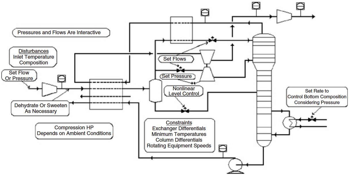
Flows depend on the pressure profile, the compression horsepower available, and the efficiency of the turboexpander. When more horsepower is available, such as at night and in cooler weather, then the flow can be increased or the pressure on the demethanizer can be lowered to increase NGL recovery for a given flow demand. Control of the NGL quality, typically for methane or carbon dioxide in ethane, becomes more difficult as tower pressure is adjusted. The multivariable controller can determine the correct heat input as tower pressure is adjusted to maintain maximum recovery and product quality. Pressure-compensated temperature is a key element of this strategy.
Other controlled variables can be minimum and maximum flows, pressures, temperatures, levels, speeds, etc. Demethanizer pressure, flow splits, reboiler flow, and plant inlet pressure are some manipulated variables, while disturbances such as residue Piping System of pressure vessels on gas tankerspipeline pressure, inlet flow, and inlet composition are considered.
In the aforementioned manner, a “team” of key controllers is pushing the plant to its optimum operating point at all times. Controllers are effectively decoupled, thereby making adjustments similar to an automobile on cruise control. In many regards, the objectives of statistical process control are achieved.
Figure 2 shows the beneficial effects of advanced controls. First the variability of the process is reduced by the ability to control closer to set points with the model predictive capability. Once variability is reduced, then the process can be pushed closer to the operating constraints where maximum profitability is attained.
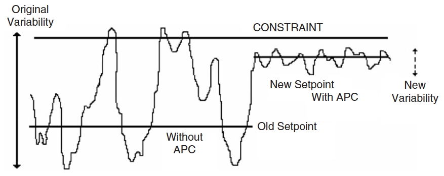
This is an area where operators hesitate to operate due to the possibility of exceeding a constraint. With advanced process control, set points can be put closer to these constraints without fear of exceeding the constraints.
Optimization
The next level of automation is optimization. For simpler optimization problems, linear programming (LP) techniques can be employed.
Nonlinear techniques may be warranted for more complex optimization opportunities where linear methods would miss significant benefits. With the advances in computing power and optimization mathematics, online, rigorous optimization has become a reality. Again, petroleum refining is leading the way, but several gas processing applications have been developed.
Read also: The Resurgence of Liquefied Natural Gas in the Atlantic Basin and Qatar
Optimization systems must rely on a multivariable predictive control system. As the robustness of the multivariable predictive control system improves, so does the effectiveness of the optimization system. With the business focus that optimization brings, multivariable predictive control developments should address the requirements of operations management. Table 1 details recent technology developments that have improved operations management and the benefits of multivariable predictive control applications. These advancements have enhanced basic process operations.
| Table 1. Recent Developments in Multivariable Predictive Control Technology | |
|---|---|
| Development | Technology |
| Nonlinear controllers | Neural nets and other empirical modeling techniques |
| Automated process testing | Multistep, random frequency testing |
| Performance monitoring | Metrics for model adequacy |
| Remote implementation and support adaptive | Web-enabled applications |
| Background testing and model identification | |
| Control system embedded | Powerful processors coupled with programming efficiencies |
This enables staff to be reployed and provide more valuable operations functions that provide increase efficiency, reliability, reduced cost, improved quality, ideal staffing, and responsiveness to changing business requirements.
Networking and Web capabilities continue to impact advanced applications. Some companies have central support centers or have contracted application service providers. Automated testing can be easily monitored remotely. Performance monitoring technologies and tools provide clear benchmarks of expected performance. Updates and improvements can be applied remotely. These capabilities reduce project and support costs and further improve the economics of multivariable predictive control initiatives. Mixed integer programming and enhanced state-space methods are now employed to improve models and decrease the impacts of unmeasured disturbances. New developments in sensor technology supply new valuable, low-cost process information. Methods for property estimation and predicting the behavior of multiphase and complex reaction systems are also improving. Multivariate statistical methods continue to progress.
Visualization technology may be a key to making the models transparent to the end user.
Leveraging Automation
In order to get the most benefit, the automation platform should be leveraged to its maximum capability. The platform itself is about 80 % of the cost for about 20 % of the potential benefits. A multitude of additional benefits are there for a fraction of the platform cost by adding applications. Include adequate instrumentation upfront for grassroot plants and during retrofits for existing plants. It is much more cost effective to add instrumentation during construction rather than adding it later. Use control system consultants rather than relying solely on equipment manufacturers.
Many equipment manufacturers are penalized for including more instrumentation than their competitors. For control system upgrades, do not just replace in kind; replace and enhance. A DCS gives limited additional value when used simply as a panel board replacement.
Automation Upgrade Master Plans
Many gas processors have developed automation upgrade master plans for existing facilities where the relative benefits of each unit and the value of enhancements are estimated. In this way the area with the most benefits can bear the majority of the initial cost of the platform. Additions to the platform, once the infrastructure is in place, typically cost less per I/O than the initial installation. Master plans are quite effective when the gas processor teams with an automation consultant. The consultant can share their past experience and advise of future developments that should be considered.
Determining the Benefits
The benefits of a fully leveraged automation system are numerous and include the following.
- Control room consolidation (reduced manpower).
- Plant reliability (uptime).
- Plant stability (better efficiency due to fewer process upsets).
- Maintenance management (reduced inventories).
- Product quality (fewer off-specification penalties or give away of overprocessed product).
- Continuous constraint pushing (increased throughput and recoveries as well as energy savings).
- Optimization (energy savings and increased recoveries).
When approached appropriately, these benefits are quantified easily. The key is measuring through baselining and monitoring the results through proper metrics.
Baselining. A good baseline is a crucial element of determining benefits. Historical data are necessary to derive a good baseline. Historical data should include the primary measurement as well as any factors that should be used to normalize the result. For instance, ethane recovery should be normalized for inlet gas flow and composition as well as ambient temperature. Data during upset periods and outliers should be discarded. True process variability is measured best with frequent data capture on the order of every minute. High-quality baselining requires an excellent understanding of the operation in addition to statistical analysis. In addition to measuring mean performance of a process, baselining will reveal the amount of variability in the process and the source of the variability. Reducing variability is one of the main benefits of automation. With reduced variability, the process has freedom to shift to a more beneficial operating point.
Statistical Analysis. Statistical analysis is crucial in determining the benefits of automation. A good statistical analysis will give the most accurate assessment of process performance under changing conditions. Mean or average performance is always the final measure between before and after performance. Again, the mean should be evaluated on a normalized basis so that the performance is assessed on a fair or equivalent basis. Total liquids or even total ethane recovered is not a normalized evaluation. Barrels per MMCF of inlet is a better metric, but does not take into account changes in inlet composition. Recovery levels take into account inlet composition, but not process capability under variable inlet rates or ambient conditions that provide more mechanical horsepower availability.
It will be interesting: Understanding Liquefied Gas Manifolds – Size Categories, Positioning, and Specific Designs for LPG & LNG
Standard deviation gives a measure of the amount of variability for a normal (bell-shaped) response curve. Depending on the process and the sources of variability, anywhere from one-half to two standard deviation improvement is reasonably expected. One way to check this is to compare best performance or process capability (entitlement) to the mean performance. This difference can be compared to the standard deviation to give an idea of the maximum standard deviation improvement possible.
Because standard deviation gives an absolute number and is difficult to compare to the mean, coefficient of variation, which is the standard deviation divided by the mean, gives a relative measure of standard deviation. In other words, the coefficient of variation gives a percentage improvement potential. All responses are not normal or bell shaped. Kurtosis is a measure of the skewness of the response curve and should be considered when evaluating standard deviation. A common example of an abnormal response is when a process runs close to its physical limits to the upside or downside and far from its physical limits to the opposite side.
Source: Unsplash.com
Elimination of upset conditions can sometimes shift a response curve close to normality. Multivariable control packages also include the capability to further identify the dynamic performance of a process with tools such as autocorrelation, power spectrum, and Fourier transforms. Determining financial benefits in the face of uncertainty is always a challenge. Even though we may have a good gauge on process improvement potential from the standpoint of increased product, the value of these improvements is dependent on economic conditions such as pricing, feedstock availability, and product demand. Risk management tools, such as Monte Carlo simulations, can be used to establish the range and certainty within these ranges of financial benefits over the variety of conditions anticipated.
Performance Improvement Initiatives. Many companies are adopting Six Sigma and other statistically founded performance improvement initiatives. Automation can greatly enhance the effectiveness of Six Sigma and other performance improvement initiatives. Conversely, the rigor of these performance improvement methodologies is useful in documenting the benefits of automation. Take Six Sigma as an example of how performance improvement methodologies and automation complement each other. The four phases of Six Sigma include measure, analyze, improvement, and control.
Measurement can sometimes be difficult and painful without automation. With automation and data historians, the measurement and analysis task becomes much easier. After data are collected, the process capability assessment, run charts, cause-and-effect matrices, and so on can be developed to assess the performance improvement opportunity and where to focus the effort. The many elements of automation can be the enabling technology for the implementation and control phases of Six Sigma.
Stabilizing the process is always a key element of performance improvement and is enabled by automation, especially advanced controls. The control phase pretty well speaks for itself.
Condensate Stabilizer Case Study
The following case study reviews an application of some of the advanced control features and the benefits. This case study is for an actual condensate stabilization process. The main reason for advanced process control on this unit was for quality purposes. Condensate product must meet a Reid vapor pressure (RVP) specification as defined by the customer. The previous method of production relied on laboratory sampling to verify the RVP, which was infrequent. Online analyzers are available but can be expensive. Instead of an online analyzer, the important quality measurement was derived through inferential means. The APC solution provided a stable plant and reduced the RVP variation.
BG Tunisia implemented multivariable predictive control on their gas condensate production system at the Hannibal plant in Sfax, Tunisia. The aims of the project were to maximize condensate yields, improve the stability of the condensate stabilization process, and ensure that quality limits for the product are adhered to at all times. BG Tunisia’s Hannibal terminal processes gas at 5,4 MMSCM/D with the condensate column operating at a typical rate of 550 l/m controlling RVP to a maximum limit of 12 psia. Condensate can be sold as crude oil and is therefore more valuable than the alternative Gas Conditioning and Natural Gas Liquids Recovery Technologiesnatural gas liquids products.
Figure 3 shows a detailed schematic for the condensate process. The liquid hydrocarbon condensate is brought into the plant from the slug catcher and is preheated in the stabilizer feed/bottoms exchanger E-0201. The preheated feed is flashed in the stabilizer feed drum D-0201.
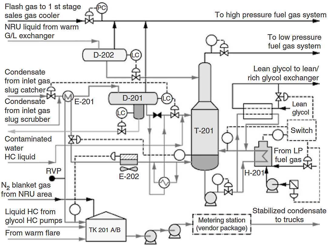
Liquid from the feed drum is further preheated through the feed/bottoms exchanger E-0250 and fed to the stabilizer T-0201 on local flow control FC-02016. The feed drum level controller LC-02007 maintains the level by manipulating the feed to the drum. The flashed vapor is sent to the high-pressure fuel system. A boot is provided on the feed drum to separate any entrained water, which is sent to the warm flare drum under level control.
Condensed hydrocarbon liquid from the warm separator (D-0701) in the nitrogen rejection unit (NRU) is fed to the NRU liquids flash drum D-0202 under level control via the warm gas/liquid exchanger E-0702 in the NRU.
The flashed vapor is sent to the high-pressure fuel system, and liquid from the drum is fed to the stabilizer on level control LC-02026.
The condensate stabilizer T-0201 reduces the vapor pressure of the condensate by removing the lighter components. It is a stripper column with 24 trays. Liquid from the stabilizer feed drum is fed at the midpoint on tray 9, and liquid from the NRU liquids flash drum is fed to the top tray. Overhead vapor from the stabilizer is sent to the low-pressure fuel system through a back-pressure control valve that maintains the tower pressure to set point under the action of PC-02045.
Read also: Innovations in LNG Import/Export Streamlining
The bottom part of the tower is divided into two sections by a baffle; the baffle does not extend to the very bottom of the tower so there is some mixing between the two sections. Liquid from the bottom tray flows into the section that is preferentially pumped through the fired stabilizer reboiler H-0201. The two-phase stream from the reboiler is returned to the other compartment where the liquid is separated as stabilized product and the vapor flows up the tower to provide stripping action.
The glycol/condensate exchanger E-0203 provides additional heat duty if required.
Stabilized condensate leaves the stabilizer on level control LC-02001, is air cooled in the condensate cooler E-0202 and by exchange with cold inlet feed condensate in the exchanger E-0201, and is sent to the condensate storage tanks TK-0201 A/B.
The main objectives of the condensate stabilizer connoisseur controller are as follow.
- Control RVP to an operator-specified target value.
- Enforce any specified unit operating constraints at all times.
- Stabilize the unit operation.
The controller uses a real-time online estimate (inferential) of RVP. By controlling more tightly to the target value, excessively high RVP and the associated increased flashing of stabilized condensate in the storage tanks and during tanker transfer can be minimized, thus reducing losses.
The product specification for RVP is 10-12 psia. Figure 4 shows the before-and-after trends of key process variables. The baseline assessment before APC was a mean RVP of 12,25 psia with 1 SD of 0,43. After APC was installed, the standard deviation dropped to 0,26, enabling control to 11,5 psia with 95 % confidence on the 12-psia limit.
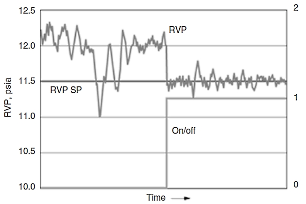
Constrained optimization drives the process to an optimum without violating process constraints such as the RVP limit imposed by the condensate purchaser.
A hybrid RVP sensor using both first principle and neural network technology provides a continuous measurement for control. Laboratory samples taken on a periodic basis are integrated into the control scheme, improving accuracy and ensuring that product quality is maintained.
It will be interesting: New and Emerging LNG/CNG Markets
The inferential estimate is implemented directly within the controller as a hybrid of a first principles model based on the Antoine vapor pressure equation and a radial basis function neural network. Both the first principles model and the neural network require the stabilization column base temperature (TI-02035) and top vapor pressure (PC-02045).
Compensation for process drift and process measurement error is via feedback from the laboratory analysis. A weekly laboratory sample is inserted as a minimum for this purpose.

- Breyfogle, F. W., “Implementing Six Sigma”. Wiley, New York (1999).
- Canney, W., Advanced process control powers developments in operations management. Oil Gas J. 102(42), 50 (2004).
- Capano, Dan, Distributed Control Systems Primer, DTS, Inc.
- Hotblack, C., BG Tunisia’s advanced process control improves condensate product stability. World Oil Mag. 225, 9 (2004).
- Kean, J., “Maximize Plant Profitability through Control Loop Optimization”. Paper presented at the 79th GPA Annual Convention, Atlanta, GA (March 13-15, 2000).
- Poe, W. A., and Harris, S., “Gas Processing Plant Automation A-Z”. Paper presented at the 84th GPA Annual Convention, San Antonio, TX (March 13-16, 2005).
- Rinehart, N. F., “The Impact of Control Loop Performance on Process Profitability”. Paper presented at AspenWorld-97, Boston, MA (Oct. 15, 1997).
- Shinskey, F. G., “Process Control Systems: Application, Design and Tuning”. 4th Ed. McGraw-Hill, New York (1996).