Liquid Cargo Handling is essential for ensuring the safe and efficient transport of various liquids, including chemicals and cryogenic substances. Effective handling involves understanding the properties of the cargo, selecting appropriate containment methods, and implementing safety measures. Moreover, employing advanced technologies and monitoring systems can significantly enhance operational efficiency.
Proper training for personnel is also crucial, as it helps prevent accidents and ensures compliance with relevant regulations. Ultimately, efficient liquid cargo handling not only safeguards the cargo but also protects the environment and public safety during transit.
Introduction
The carriage of cargo includes a loaded voyage and an ballast voyage, where coolant is carried to maintain tank temperature, gas change, etc.
During loaded voyage, it is necessary to maintain strict control of cargo temperature and pressure, for all refrigerated and semi-pressurized gas carriers. This is achieved by re-liquefying cargo boil-off and returning it to the tanks. During this operation, incondensibles must be vented as necessary to minimize compressor discharge pressures and temperatures. In LNG ships, the boil-off is burned as fuel in the ships boilers. During a ballast voyage, it is a practice to retain a small quantity of cargo on board after discharge and the amount retained is known as the heel. This product is used to maintain the tanks at reduced temperature during the ballast voyage. This procedure applies only when the same grade of cargo is to be loaded in the next voyage.
In general, the quantity retained depends on:
- Commercial agreements.
- The type of gas carrie.
- The duration of the ballast voyage.
- The next loading terminals requirements, and
- The next loading grade.
In the case of LNG carrier, as much as, 2 000 to 3 000 cubic meters of liquid may be retained at departure discharge port, whereas, in LPG ships, the small amount of liquid kept as heel should be sufficient to provide necessary cooling effect during the ballast voyage and to reach loading terminal with tanks suitably cooled and at lower pressures.
Reliquefaction
Reliquefaction plant requirements: The number and capacity of the reliquefaction units fitted depends on the service for which a ship is intended and the number of segregated cargoes it is designed to carry. The plant is designed to maintain the cargo temperature at a level such that the pressure does not exceed the relief valve setting under the most extreme service conditions, usually taken as, 45 degrees air and 32 degrees seawater. Spare capacity of at least equal to the largest single unit has to be provided. Where two or more refrigerated cargoes, which may react chemically in a dangerous manner, are carried simultaneously, the refrigeration system must be completely isolated from each other by removable pipe sections or other means so as to prevent mixing of the cargoes.
The essential duties of reliquefaction plant are:
- to cool down cargo tanks and associated piping before loading;
- to reliquefy cargo vapour generated during loading and return it to cargo tanks;
- to keep the cargo at a temperature and pressure within the design limits of the cargo system during transport.
Parts of reliquefaction plant can often be used for following auxiliary functions:
- ≤ – on semi-pressurised ships, the cargo compressors can raise the tank pressure enough to prime deck mounted discharge pumps prior to discharge. Cargo vapour is drawn off and compressed, and the hot gas discharged is returned to the cargo tank. When the cargo tank pressure is sufficient (about 2 barg) the liquid valve is opened and the tank pressure will deliver liquid to the pump suction.
- ≤ – the cargo compressors can be used to boil off cargo residues left in the pump sumps at the end of discharge. The cargo compressor draws vapour from the tank and compresses it, the hot vapour discharge being returned to the cargo pump sump through an open ended pipe immersed in the remaining liquid, or a perforated heating coil which is sometimes provided. Alternatively the hot vapour can be circulated through closed heating coils to evaporate remaining liquid.
Reliquefaction plant operations: Before starting reliquefaction plant, the responsible officer should ensure that –
- Compressor lubricating oil is suitable for cargo concerned and that oil levels are correct.
- Lines and valves are correctly set, compressor discharge valve should always be opened before starting.
- Full seawater supply to appropriate condensers has been established.
- The glycol plant is running.
- Variable capacity compressors are set to manual operation at minimum capacity.
- Enough power is available for starting.
Simple Gas Reliquefaction Cycle:
- The cargo tanks (1). In the direct reliquefaction system these act as evaporators in which the liquid cargo is vaporized. Evaporation removes a certain quantity of heat Q1 from the tank, and its surrounding.
- A mechanical compressor (2) The vapour formed in the cargo tanks is at a pressure P1; the compressor draws and compresses it, and delivers it to condenser at a pressure P2. in the process of compression an amount of heat energy Q2 is added to the gas; the compressor uses an equal amount of energy W1.
- A condenser (3) The vapour supplied by the compressor is liquefied in the condenser, giving up a certain amount of heat Q3 to the cooling water.
- An expansion valve (4) This reduces the pressure of the condensate from P2 to P1 while passing from the condenser to the cargo tank.
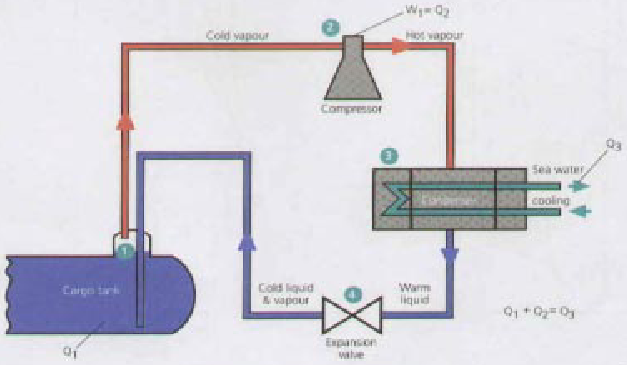
According to first law of Thermodynamics:
Reliquefaction With Intercooling
The reliquefaction cycle works on the principle of removing excess heat from the boil-off vapour, condensing it and returning the liquid to the Independent Cargo Tankscargo tank. The heat removed is the latent heat of vaporization of the cargo plus any extra heat (or superheat) the boil off has absorbed.
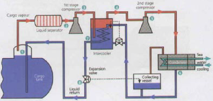
If the compressor discharge to suction pressure ratio in a single stage system exceeds about 6:1 the efficiency of the machine is reduced and two-stage compression is necessary. This can take place in two separate machines or in two-stage compressor. Boil-off (1) is taken from tank via a liquid separator to the first stage compressor (2) where it is superheated (3). An intercooler (4)is provided to cool the superheated vapour before passing to the second stage compressor (5). The purpose of the intercooler is to reduce the suction temperature of the second stage and increase efficiency; it is essential for a cargo such as Ammonia. The second compression further superheats the vapour which is then cooled and condensed, in a seawater cooled condenser (6). The ambient temperature liquid is then collected and passed through the expansion valve (8). Before the expansion valve, the condensed liquid can be used as intercooler coolant (7). This system can be used for semi-pressurised and fully refrigerated.
Reliquefaction Without Intercooling
The single stage direct cycle is particularly suited to the semi-pressurised carrier. The cycle is used where suction pressure is relatively high, so that the discharge to suction pressure ratio reduces. In the simple cycle the boil-off vapour (1) from cargo tank are taken by the compressor (2) via a liquid separator. The compressor increases pressure and temperature of vapour.
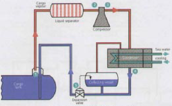
The superheated vapour (3) are then cooled and condensed to liquid in the condenser (4), using seawater as cooling medium. The liquid is collected in a vessel known as the condensate receiver, before being passed through an expansion valve (5) to cool it. The flow through the expansion valve is controlled by a level switch in the condensate receiver, to prevent back-pressure from the cargo tank reaching the condenser and compressor. The throttling (expansion) valve is designed to ensure that there is sufficient pressure to press the liquid into the cargo tank.
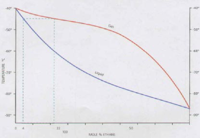
Ethylene Cargo
Ethylene is one of the primary petrochemical building blocks, used in the manufacture of:
- polyethylene plastics;
- ethyl alcohol;
- polyvinyl chloride (PVC);
- antifreeze;
- polystyrene;
- polyester fibre, etc.
It is obtained by cracking either naphtha, ethane or LPG. About 85 million tones of Characteristics of Natural Liquefied Gasesethylene is produced worldwide but only 2,5 million tones is moved long distance by sea on semi-pressurised vessels.
Ethylene carriers are most sophisticated of the semi-pressurised tankers and have the ability to carry not only most other liquefied gas cargoes but also ethylene, as its atmospheric boiling point is –104 degrees. The first ethylene carrier was built in 1966 and, as of 1995, there were about 100 such ships in service ranging in capacity from 1 000 to 12 000 cubic meters. Of these very few ships fall into special category being able to handle wide range of liquid chemicals and liquefied gases simultaneously. These ships have cylindrical, insulated, stainless steel cargo tanks able to accommodate cargoes up to a maximum specific gravity of 1,8 at temperatures ranging from minimum of –104 degrees to a max. of +80 degrees and at a maximum tank pressure of 4 bar. The ships can load and discharge virtually at all pressurized and refrigerated terminals.
Ethylene ships are often built for specific trades but will also operate carrying LPG or chemical gases. In fully refrigerated ships ethylene is carried at its atmospheric boiling point –104 degrees. Normally Type ‘C‘ pressure vessel tanks are used and no secondary barrier is required. Thermal insulation and high-capacity requefaction is fitted on this type of ship. A complete double hull is required for all cargoes below –55 degrees, whether the cargo tanks are of Type «A», «B» or «C».
Cascade Cycle
The cascade cycle is used for fully refrigerated cargoes where a special refrigerant such as R22 is used to obtain the lower carriage temperatures. Also in these systems, the refrigeration plant capacity does not depend on seawater temperature changes as with other reliquefaction cycles. For the carriage of ethylene this type of equipment is essential. The system is virtually identical to single stage direct system, except that the cargo condenser is cooled by the refrigerent gas such as R22. The heat from cargo evaporates the R22, which is compressed, condensed in a seawater-cooled condenser, and cooled by passage through expansion valve. The cycle is more efficient as the R22 temperature in the LPG condenser can be below 0 degrees.
R22 System Operation
The monochloro difluoro methane referred to as R22 refrigerant is an halogenated chloro fluoro carbon (HCFC). It is well suited to use in reliquefaction plants, using reciprocating type compressor. This refrigerant is not listed in Montreal protocol. R22 has a very low toxicity; however in the presence of naked flame breaks down into a toxic gas, which has a very strong smell.
This system is used for cargoes which cannot be compressed for chemical reasons. In this system the boil-off passes under its own pressure to a condenser, which cools and liquefies it. The condensate then returns to the tank under its own pressure or by a pump. It is also possible to arrange condensation by cooling coils in the vapour dome, below the liquid surface or welded to the tank exterior.
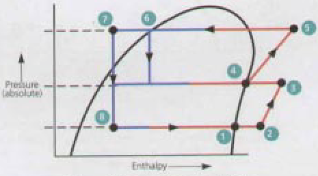
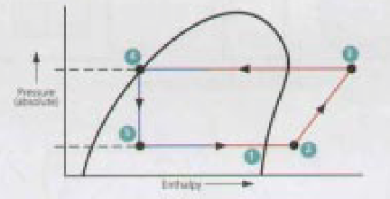
Mollier Diagram. The below figure depicts the principal feature of Mollier diagram for propane. The predominant feature of this diagram is the rounded conic shape of the liquid/vapour mixture area. This is enclosed by a saturated liquid line & saturated vapour line, which meet at the apex, which is the critical part. As will be seen, the diagram also contains lines of constant temperature, constant volume, constant entropy and dryness fraction.
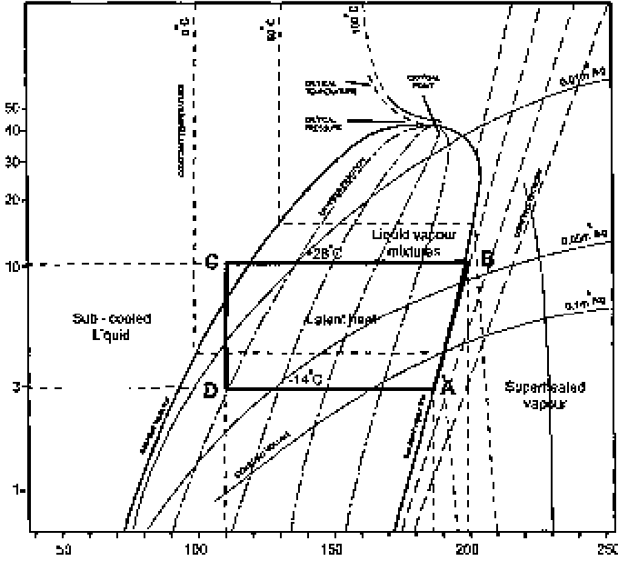
The above Mollier diagram covers the boil off vapour of propane carried at 3 bar & -14 °C.
At A on the diagram, the boil-off vapour is drawn from cargo tank and adiabaticaly compressed to 10 bars at B. The difference in enthalpy between B and A (50 kJ/kg) represents the work input to the vapor by compressor.
Read also: Liquefied Natural Gas Reliquefaction Plant
From B to C heat is taken from vapour and is condensed to sub-cooled liquid. The enthalpy change from B to C (370 kJ/kg) represents the heat removed by the condensor. The liquid condensate is then expanded through expansion valve and returned to ships tank at a pressure of 3 bars. In the expansion process, the the condensate neither gives up nor receives heat and thus there is no change of enthalpy. In the expansion process, the change in sensible heat exactly matches the ingress of latent heat required for flash evaporation. The line CD is, therefore, vertical and the position of D indicates the dryness fraction of 0,2 for the return condensate i. e. 20 % vapour and 80 % liquid.
The total refrigeration effect of the cycle is the difference between the enthalpy at A and that at D (320 kJ/kg).
Direct Cycles. Is descriptive of a system, where the boil off is compressed, condensed and returned to the tank. This is most common system but may not be employed in certain gases. There are three main types of direct cycle reliquefaction plant and these are described as follows.
Direct Compression Cycle. A simplified diagram is shown in figure. This cycle is suitable where suction pressures are relatively high as in the carriage of semi-pressurized products. Boil-off vapors from the cargo tank are drawn off by the compressor in the diagram. Compression increases the pressure and temperature of the vapor. The high temperature allow it to be condensed against sea water in the condenser. The condensed liquid is flashed back to the tank via a float controlled expansion valve. The liquid/vapor mixture being returned to the cargo tank may be either distributed by a spray rail at the top of the cargo tank or taken to the bottom of the cargo tank or taken to the bottom of the cargo tank to discourage revaporization. The spray rail is normally used when the tank is empty and bottom discharge when the tank is full.
Two Stage Direct Cycle. Although two stage direct cycle equipment is relatively uncommon, it is used for those liquefied gas carriers handling a vide range of products. For grades Butadiene and vinyl Chloride its fitting is essential.
Cascade Direct Cycle. The Development of Natural Gas Liquefaction Cycles based on Energy and Exergy Analysescascade cycle is used is used for fully refrigerated cargoes where a special refrigerant is used for obtaining the low carriage temperature.
A simplified diagram is shown below.
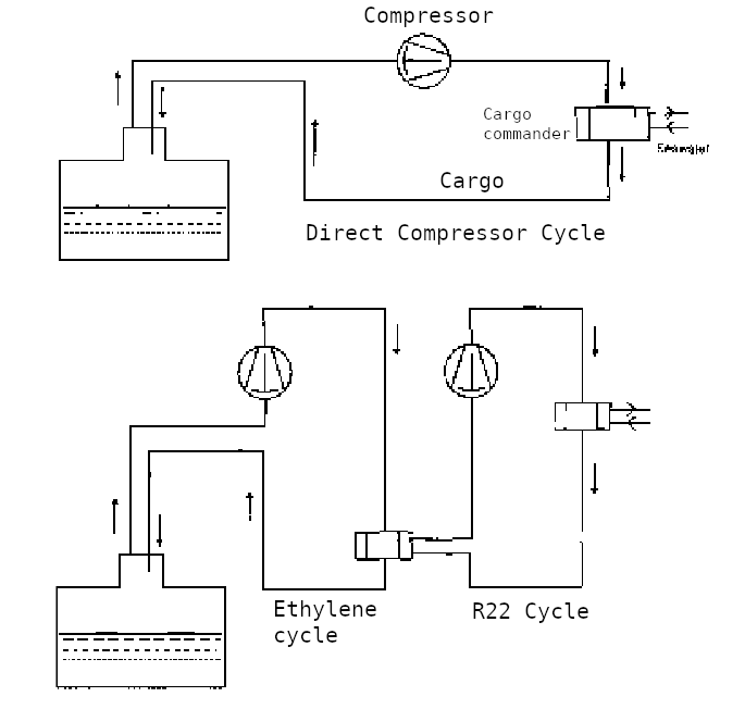
The single stage compression of cargo vapor is identical to the single stage direct cycle, but the cargo condenser is cooled using R22 instead of the sea water .the cargo in condensing evaporates the liquid R22 and the R22 vapor is then taken through a conventional R22 closed refrigeration cycle,condensing against sea water—hence the name cascade.

- Study on the completion of an EU framework on LNG-fuelled ships and its relevant fuel provision infrastructure, LOT 1 Position paper: Towards harmonized EU LNG bunkering guidelines, DNV-GL, 2016.
- Study on the completion of an EU framework on LNG-fuelled ships and its relevant fuel provision infrastructure, LOT 1 Final Report, DNV-GL, 2016.
- LNG Bunkering Guidelines IACS Recommendation n. 142, on LNG Bunkering, IACS, 2016.
- ISO/TS 18683:2015. (15-Jan. 2015). Guidelines for systems and installations for supply of LNG as fuel to ships. Technical Specification.
- Society for Gas as a Marine Fuel (SGMF). (2015). Gas as a marine fuel, safety guidelines, Bunkering. Version 1.0, February 2015.
- ISO 20519:2017. Ships and marine technology – Specification for bunkering of gas fuelled ships. (International Standard).
- IEC 60079-10-1. (2015). Explosive atmospheres – Part 10-1: Classification of areas – Explosive gas atmospheres.
- Directive 1999/92/EC – ATEX of the European Parliament and of the Council of 16 December 1999 on minimum requirements for improving the safety and health protection of workers potentially at risk from explosive atmospheres (15th individual Directive within the meaning of Article 16(1) of Directive 89/391/EEC).
- API RP-500. 1997. Recommended practice for classification of locations for electrical installations at petroleum facilities classified as CIass 1, Division 1 and Division 2. Washington. D.C: API.
- API RP-505. 1997, Recommended practice for classification of locations at petroleum facilities classified as Class I, Zone 0, Zone 1 and Zone 2. Washington, D.C. API.
- NFPA 497. 2012, Recommended practice for the classification of flammable liquids, gases or vapours and of hazardous (classified) locations for electrical installations in chemical process areas. Quincy, MA: NFPA.
- IEC EN 60079-10-1 Ed.1.0, 2008. Electrical apparatus for explosive gas atmospheres – Part 10-1: Classification of areas – Explosive gas atmospheres. International Electrotechnical Commission.
- Commission Decision 2010/769/EU of 13 December 2010 on the establishment of criteria for the use by liquefied natural gas carriers of technological methods as an alternative to using low sulphur marine fuels meeting the requirements of Article 4b of Council Directive 1999/32/EC relating to a reduction in the sulphur content of certain liquid fuels as amended by Directive 2005/33/EC of the European Parliament and of the Council on the sulphur content of marine fuels (OJ L 328, 14.12.2010, p. 15).
- USCG CG-OES Policy Letter 02-14 – Guidance Related To Vessels And Waterfront Facilities Conducting Liquefied Natural Gas (LNG) Marine Fuel Transfer (Bunkering) Operations.
- ADN – European Agreement concerning the International Carriage of Dangerous Goods by Inland waterways (Update version ADN January 2017).
- ADR – European agreement concerning the International Carriage of Dangerous Goods by Road (Update version ADR January 2017).
- Rhine Vessel Inspection Regulations (RVIR).
- EU general risk assessment methodology (Action 5 of Multi-Annual Action Plan for the surveillance of products in the EU (COM(2013)76) – Document 2015-IMP-MSG-15 – 16 October 2015.
- Safety Study, Chain analysis: Supplying Flemish ports with LNG as a marine fuel, Analysis of safety aspects, June 2012.
- EN 1160 – Installations And Equipment For Liquefied Natural Gas – General Characteristics Of Liquefied Natural Gas, NBN, 1st edition, August 1996.
- ESD Arrangements & Linked Ship/Shore Systems for Liquefied Gas Carriers, SIGTTO First Edition 2009 – SIGTTO.
- M. Kofod & S. Hartman, T. Mundt – Review of Recent Well-to-Wake Greenhouse Gas Studies evaluating the use of LNG as a marine Fuel, IMO MEPC/INF.15.
- LNG Access Code for Truck Loading for The Zeebrugge LNG Terminal – Based on version approved by the CREG on September 19th 2013 – Applicable as of January 1st 2014 – FLUXYS.
- Guidance for the Prevention of Rollover in LNG Ships – SIGTTO – First Edition 2012.
- Wang, Siyuan & Notteboom, Theo – The role of port authorities in the development of LNG bunkering facilities in North European ports, 14 January 2015, World Maritime University 2015.
- Verhoeven P (2010) A review of port authority functions: towards a renaissance? Marit Policy Manag 37:247-270.
- Society for Gas as a Marine Fuel (SGMF). (2017). Gas as a marine fuel, safety guidelines, Bunkering. Version 2.0, February 2015.
- COM(2003) 515 final – Communication from The Commission concerning the non-binding guide of good practice for implementing Directive 1999/92/EC of the European Parliament and of the Council on minimum requirements for improving the safety and health protection of workers potentially at risk from explosive atmospheres, Brussels, 25.8.2003.
- Davies, P. (2016) – Bunkering LNG: Setting the Safety Zone, 7th Motorship Gas Fuelled Ships Conference, November 2016.
- International Association of Oil & Gas Producers. (1-Mar 2010). Risk Assessment Data Directory – Process Release Frequencies. Report No. 434 – 1, 1 March 2010). Pertinent data from this report is summarised in: Davies & Fort, (Sept 2012), LNG as Marine Fuel – Likelihood of LNG Releases, Journal of Marine Engineering and Technology.
- PGS2 – TNO Yellow Book – Methods for the calculation of physical effects, due to releases of hazardous materials (liquids and gases) – CPR 14E (3rd Edition, 2005) – TNO – The Netherlands Organization of Applied Scientific Research.
- OECD Guiding Principles for Chemical Accident Prevention, Preparedness and Response, Guidance for Industry (including Management and Labour), Public Authorities, Communities, and other Stakeholders – 2nd Edition (2003) – OECD Environment, Health and Safety Publications.
- DNVGL-RP-G105 Edition October 2015 – Development and operation of liquefied natural gas bunkering facilities, Recommended Practice, DNV GL, 2015.
- USCG CG-OES Policy Letter No. 01-17 – Guidance for Evaluating Simultaneous Operations (SIMOPS) during Liquefied Natural Gas (LNG) Fuel Transfer Operations.
- LGC NCOE Field Notice 01-2017 – 14-Aug-17 – Recommended Process For Analysing Risk Of Simultaneous Operations (SIMOPS) During Liquefied Natural Gas (LNG) Bunkering.
- An Overview of Leading Software Tools for QRA, American Society of Safety Engineers – Middle East Chapter (161), 7th Professional Development Conference & Exhibition, March 18-22, 2005.
- Walter Chukwunonso Ikealumba and Hongwei Wu (2016) Some Recent Advances in Liquefied Natural Gas (LNG) Production, Spill, Dispersion, and Safety School of Chemical and Petroleum Engineering, Curtin University.


